06 February 2021 Post Number 528
In post 525, we saw a hybrid² amplifier, hybrid due it to using both vacuum tubes and solid-state, but also hybrid due to the tube portion being a voltage-out amplifier that would control the output signal, while the
solid-state portion being a voltage-to-current amplifier that blindly delivered needed current.
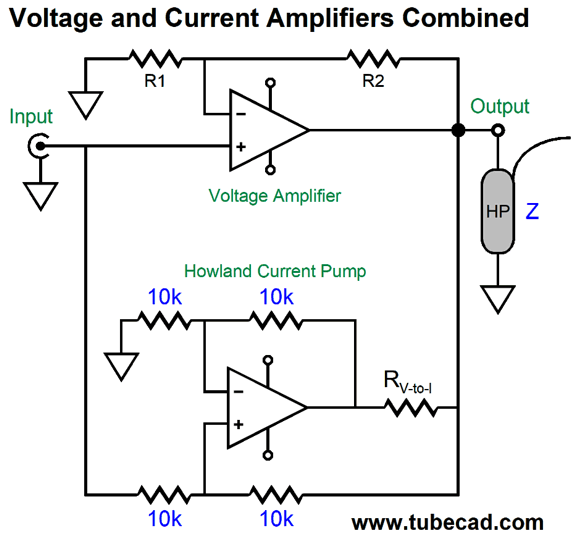
The big problem this design faced was non-flat load impedances and missing loads, as the current-out amplifier relentlessly delivers output current, even if no load is present. A current-out amplifier's optimal load is a dead short to ground. In contrast, voltage-amplifiers love high-impedance loads and fear dead shorts to ground.
In other words, I wasn't altogether happy with this design, but I thought it could be forced to work well with planar headphones due to their flat impedances; in addition, headphone jacks come in the switching style, which would allow us to load the amplifier with a dummy load resistance when the headphones aren't plugged in the jack.
While trying to imagine other solutions, I recalled the double-amplifier configuration, which I once heard called the "piggyback amplifier." The first time I encountered this topology was in 1992 in Analog Devices' book, Amplifier Applications Guide, in chapter-8 on video and other high-speed OpAmp applications.
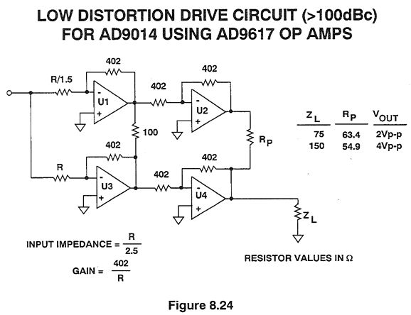
The magic behind this arrangement is the OpAmps U3 & U4 effectively see infinite load impedances, as OpAmps U1& U2 do the heavy lifting, as they put out higher gain. For example, the Rp resistor in series the ZL load resistance define a two-resistor voltage divider whose output voltage equals that of OpAmp U4. All the bottom OpAmps have to do is clean up the signals. Here is the Analog Device's explanation:
The best sentence is, "This minimizes the odd-order harmonics generated in the output stages of U3 and U4." Let's look at a simpler implementation.
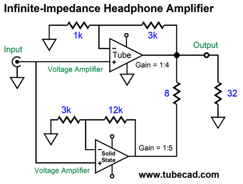
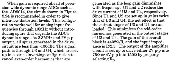
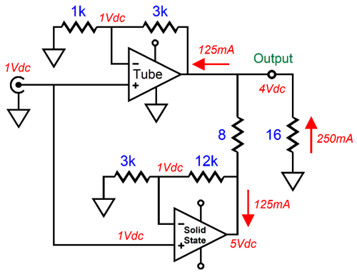
This time, the higher gain amplifier is below the lower-gain amplifier (I drew the schematic before I could find the schematic from 1992). Note how ratio between gains (4/5) equals the ratio between load impedances (32-ohms/40-ohms), i.e. 0.8. Let's apply a 1V input signal and follow the current relationships.
The solid-state amplifier must deliver all the 125mA of current flow into the 32-ohm headphone driver, as it must draw 125mA through the 8-ohm resistor. As far as the tube-based amplifier is concerned, the load impedance is infinitely high, it does not need to deliver and current into the load. What happens when the target impedance of 32 ohms is replaced with a 16-ohm headphone?
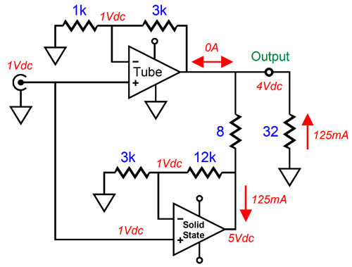
Now, both amplifier must work equally to drive the headphone. As far as the tube-based and solid-state amplifiers are concerned, the headphone impedance is 32 ohms; as far as the solid-state amplifier is concerned, the TOTAL load impedance is 40 ohms, as 5V/0.125A equals 40 ohms. Okay, let's try a 50-ohm load instead.
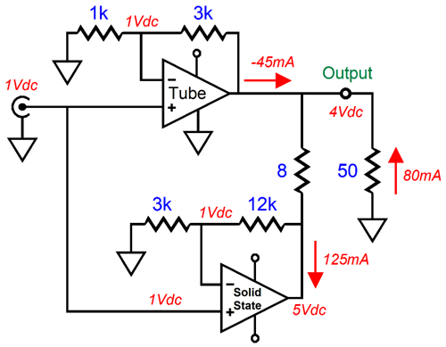
Note the reversal of current flow from the tube amplifier. The bottom amplifier pulls 125mA, 80mA from the headphone, 45mA from the tube amplifier. As far as the tube-based amplifier is concerned, the load impedance is 88.9 ohms; As far as the solid-state amplifier is concerned, the load impedance is 40 ohms. Indeed, as far as the solid-state amplifier is concerned, the load impedance is always 40 ohms. Okay, what if the actual load is missing?
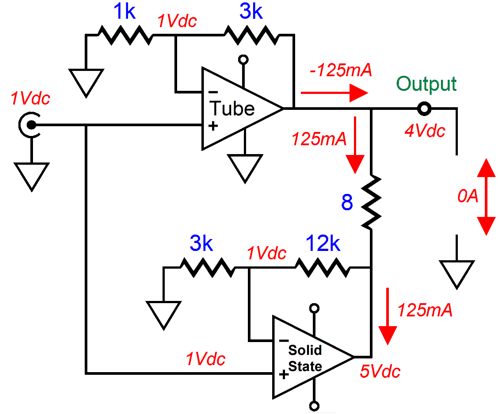
The 8-ohm resistor still sees the same 1V voltage drop and the same 125mA of current flow. The solid-state amplifier still thinks the load impedance is 40 ohms; the tube-based amplifier, 32 ohms.
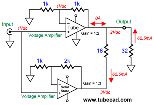
What if we lower the gain to just 1:2 or 6dB?
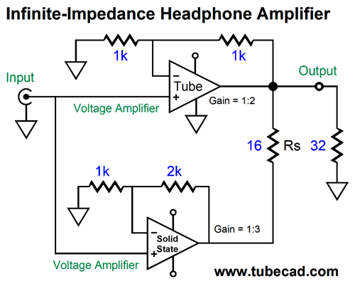
The series resistor Rs must be 16 ohms to create the infinite-impedance load for the tube-based amplifier.
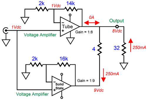
What if we desire more gain, 12dB more gain, i.e. 1:8?
The series resistor Rs must be 4 ohms. Note that the higher the gain, the lower resistor Rs must be.
How about a formula?
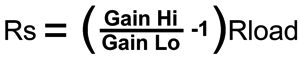
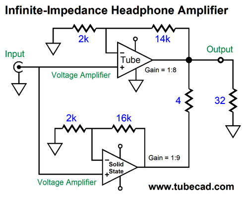
In short, the load impedance should match the target impedance, as only then will the tube amplifier see an infinite load impedance. What if you own many different headphones, each with its own unique impedance?
Click on image to see enlargement
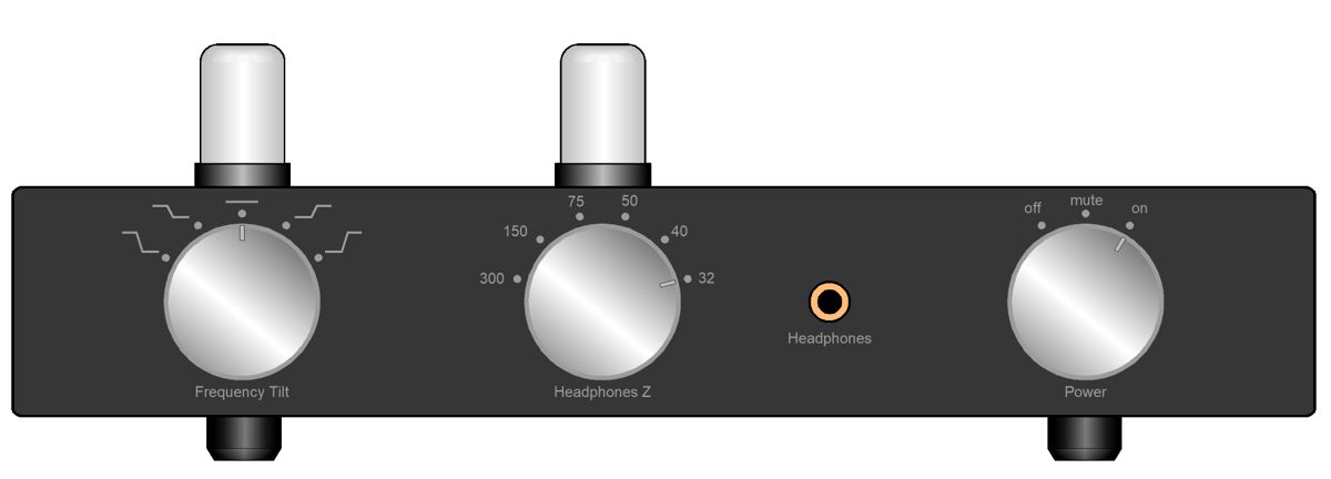
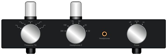
With this headphone amplifier, we select the load impedance to be driven with a rotary switch.
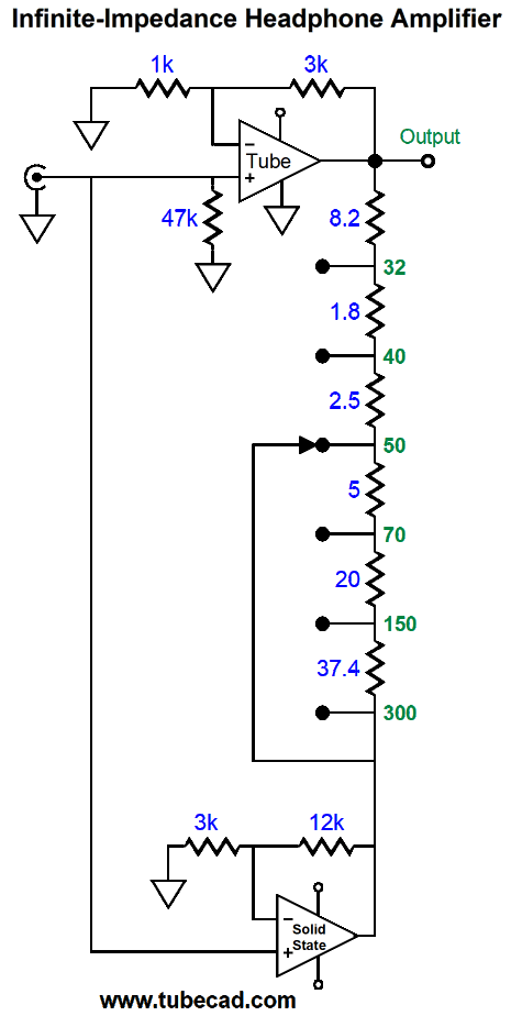
The solution is to vary the resistance that bridges both amplifier outputs. A rotary switch selects the target load impedance. Okay, what about those who hate headphones? Could we make a version that drove loudspeakers? Indeed, it is a simple matter of scale. Remember, topology is what is independent of size.
Since most loudspeakers come in only three impedances, 4, 8, and 16 ohms, we only need a three-position rotary switch. We will still face the problem of varying load impedance, as few speakers offer a truly flat impedance plot. The workaround would be to place an impedance flattening network in parallel (or possibly in series) with the speaker. I would use a 200W solid-state power amplifier and a 8W tube-based OTL amplifier, possibly a single-ended OTL.
While looking through a binder filled with old Xeroxed copies of technical articles on the topic of output transformers, I discovered a misfiled JAES paper by the great Richard H. Small on the topic of crossover design. I had only distant and faint memories of this article, which was a dang tragedy, albeit a small tragedy, as his paper could have saved me much recent mental effort.
Since encountering Mr. Small's work, I have been supremely appreciative of his discoveries, which there were many, and his writing, which was always first-rate. Modern loudspeaker design depends heavily on the famous Thiele-Small parameters, such as Qts, Qes, Qms, Fs, and Vas, for example, which are known as the Small parameters. In addition, he wrote dang well. I remember finding a single sheet of a Xeroxed article in a pile of papers, so I knew neither its author nor its title. The topic was loudspeakers; it was interesting, but I accused the writer for having so obviously plagiarizing Richard Small's prose style. When I searched the web for the author, I discovered that it was Small.
I highly recommend that you read Small's 1971 article for the JAES, if you want to dig deep into loudspeaker crossover design. Here is its conclusion:
CONCLUSION
The design of crossover networks is inextricably linked with the driver-mounting problem.
For ideal mounting conditions, constant-voltage crossover networks provide an exact solution. The most interesting feature of these networks is the consistently wide overlap region. Response in the overlap region must be carefully considered when selecting and mounting drivers for a multiple-driver loudspeaker system.
For systems having unavoidably large driver spacings, there is no perfect crossover design. Intuition suggests, however, particularly when room reverberation is considered, that in this case constant power transfer (constant-resistance) networks would provide the best results on average.
The most desirable crossover network for general use would seem to be the simple first-order network. This network provides both constant voltage transfer and constant power transfer, the least phase difference of any network design, as well as economy and simplicity of construction.
I read his article in high school, when it appeared, as San Jose's main public library was smart enough to carry the Journal of the Audio Engineering Society. It proved a huge inspiration to me. At the time, I was far more mathematically inclined than I am today and his formulas were a godsend to me. What I clearly didn't appreciate was a schematic on the article's last page.
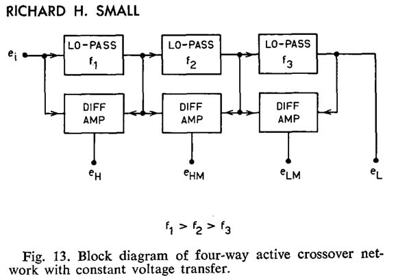
This is an overview of a four-way active crossover for loudspeakers. What is stunningly amazing is that it must always yield both a flat frequency response and phase response, regardless of what the filter orders are. In fact, we could mix 1st with 2nd and 3rd. Let's look at the fleshed out version of Small's schematic.
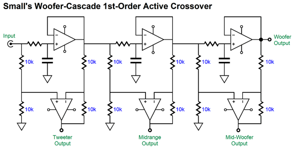
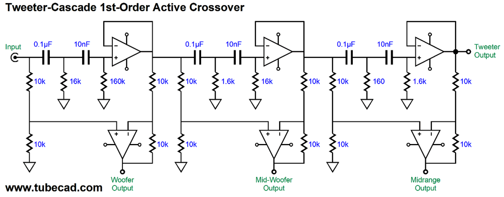
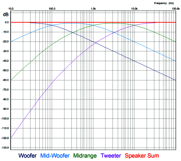
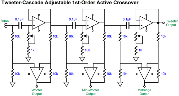
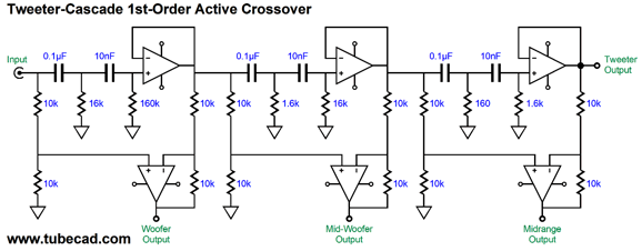
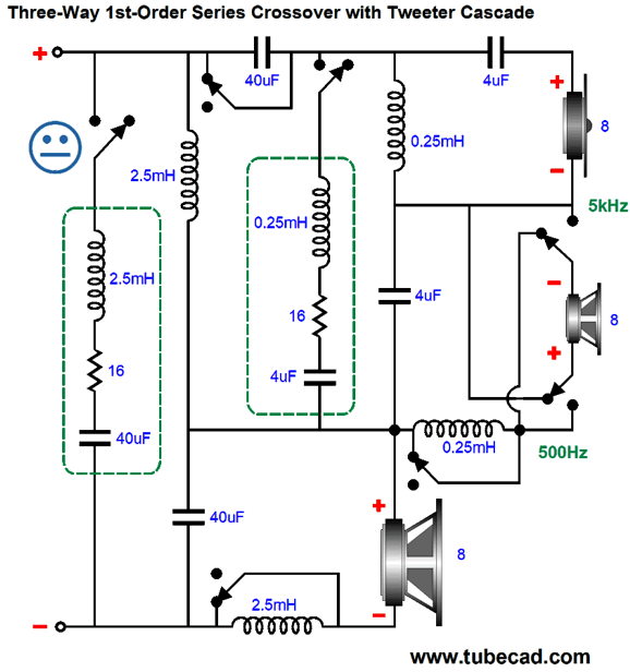
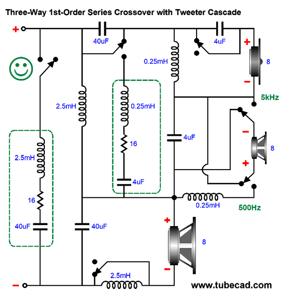
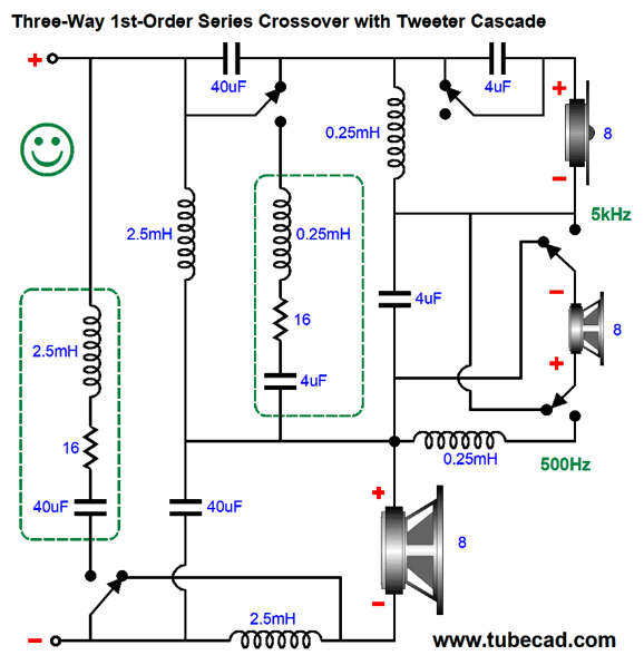
Note the cascade of 1st-order low-pass filters, so the woofer sees the steepest slopes; the tweeter, the least. This arrangement favors clarity, as big, heavy drivers simply cannot deliver high-frequencies without beaming, distortion, and attenuation. On the other hand, we could favor tweeter survival. Tweeters are delicate. When faced with low-frequencies and high power, they melt. (Often when a tweeter blows, it produces a single beautiful, but expensive, smoke ring.) Let's look at a tweeter cascade that places three high-pass filters in series.
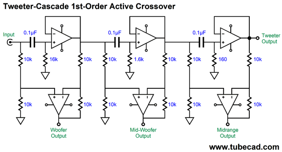
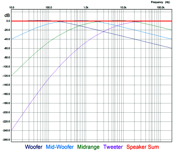
This is a first-order crossover with crossover frequencies of 100Hz, 1kHz, and 10kHz. Perhaps, these are silly crossover frequencies, but imagine a large woofer working below 100Hz, then two 5-inch fullrange drivers covering 100Hz to 10kHz, with the tiny tweeter handling the last octave of 10kHz to 20kHz.
The great thing about this circuit is that it could easily be made variable. I love test equipment. An LCR (inductance, capacitance, resistance meter) is a godsend when matching capacitors or finding the inductance of an unmarked choke. Tone-burst generators give a much-improved test of power amplifier behavior. Oscilloscopes let us see voltages in motion. An adjustable active four-way crossover might make designing a loudspeaker far easier, as we could spin rotary switches until we were satisfied; then, we would make a passive crossover to match the optimal crossover frequencies. The alternative, fiddling with passive crossover part values, is both tedious and expensive. Moreover, the huge time lag between listening sessions undermines our sonic evaluations.
We could use linear potentiometers, but I prefer rotary switches. In fact, the Trim-1 11-position stepped attenuators would work perfectly.
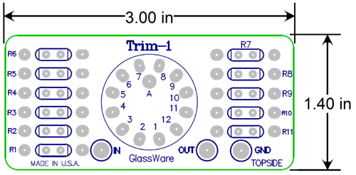
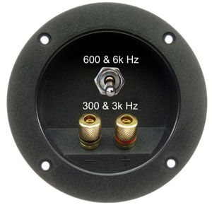
Indeed, I would double up on the last switch, so we could make both 1kHz and 100Hz adjustments to the final crossover frequency. For example, if we wanted to cross over the tweeter at 6300Hz, we would select 6kHz on the left switch and 300Hz on the right switch.
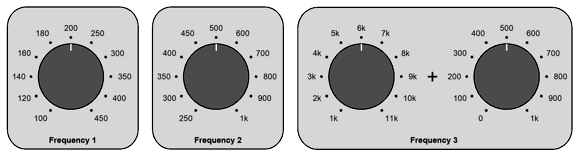
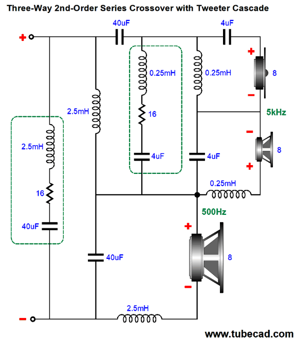
The two Trim-1 stepped attenuators would be simply wired in series. Okay, let's now look at a 2nd-order example.
Click on schematic to see enlargement
Each high-pass filter is a Linkwitz-Riley alignment, with a -6dB droop at the crossover frequency and a Q of 0.5. Once again, the crossover frequencies are 100Hz, 1kHz, and 10kHz. Interestingly enough, that is not what the frequency plot lines look like.
Seemingly, the crossover frequencies are all doubled; they aren't. Also note the tweeter cascade of high-pass slopes, but 1st-order slopes on the low-pass sides of the crossover frequencies. In fact, the woofer, midrange-woofer, and midrange output sees a small bump, although the total output sums to flat.
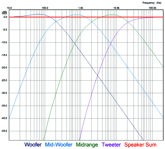
If we had opted for a woofer cascade of low-pass filters, the midrange-woofer, midrange, and tweeter output would see a small bump and 1st-order high-pass slopes.
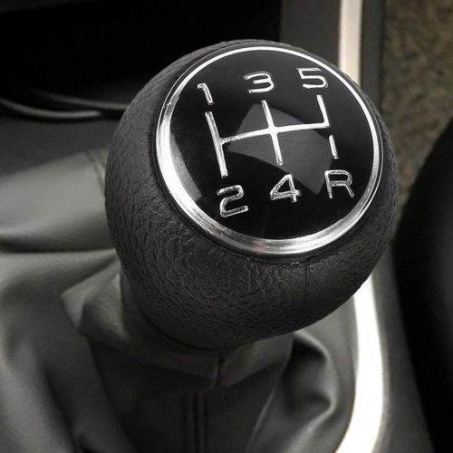
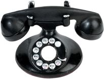
Shifting is fun. As a teenager I disdained automatic transmissions in cars. Stirling Moss* didn't let the transmission do the shifting for him as he won 212 of the 529 car races he entered. In fact, my first car, a Triumph TR-3 lacked a synchro cone between first and second gears, so I had to double-clutch (aka double de-clutching) to make a smooth transition between those two gears. When I told my children this, they stared at me blankly in the same fashion that they did when I explained what a rotary phone and a floppy disk were.
Well, what if loudspeaker crossovers allowed shifting? What would we shift? Two possibilities are frequency and slope. Imagine a loudspeaker that held a 1st-order three-way crossover, with crossover frequencies of 300hz and 3kHz between an 8-inch woofer and 5-inch midrange and 1-inch dome tweeter. The 1st-order crossover is a constant-voltage, phase-flat, constant impedance crossover that delivers the best waveform fidelity—but only if you can get away with it, which is difficult as the shallow slopes require wide bandwidth overlap and offer little protection to the high-frequency drivers. Our imagined loudspeaker gets away with it when playing refined and polite music, such as string quartets and acoustic folk music, but falters on raucous rock music and strident symphonic works. In this example, a shift either of frequencies or of slope would save the day.
Here is another possible scenario: a 20W tube-based amplifier versus a 200W solid-state amplifier. The speaker can survive the 1st-order crossover frequencies of 300hz and 3kHz with the 20W tube amplifier, but not with the 200W solid-state amplifier. (A 20W solid-state amplifier might not be any better, as the tube amplifier's output transformer is so bandwidth-limited that it prevents pure square-waves from reaching the loudspeaker; the small solid-state power, on the other hand, will clip often and it will pass these approximations to square-waves just fine.) In order to use the solid-state power amplifiers, we must either increase the crossover frequencies or increase the crossover slopes.
Let's imagine that when we flip the switch on the back of the loudspeaker, the crossover frequencies shift to 600hz and 6kHz. True, the woofer now extends further into the midrange frequencies, just as the 5-inch driver must now reproduce higher frequencies, but the midrange and tweeter drivers no longer catch on fire. Alternatively, we could forgo the inherent purity of the 1st-order slopes for the greater protection afforded by the 2nd-order crossover, while retaining the original crossover frequencies of 300Hz and 3kHz. Let's start with the first possibility: changing the crossover frequencies in a 1st-order crossover.
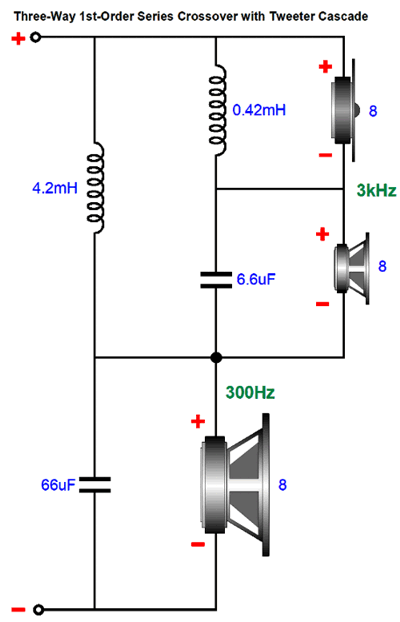
The crossover arranges in the series configuration, so no bi-wiring is possible, but the tweeter does see a crossover cascade, so both the 300hz and 3kHz high-pass filters cascade, offering greater protection for the tweeter. To double the crossover frequencies requires halving the capacitor and inductor values. So, how do we make the two sets of crossover frequencies switchable (i.e. capable of being shifted)? Here is how I would do it: I would use twice as many capacitors and inductors.
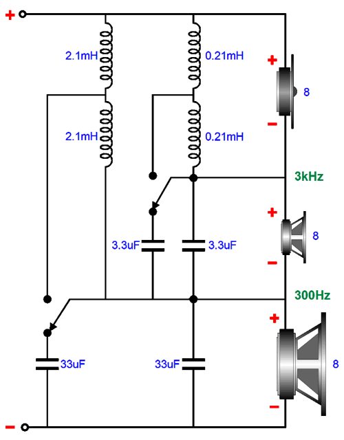
The capacitors in parallel and the inductors in series add together; thus, the two 3.3µF capacitors form 6.6µF of capacitance, while the two 2.1mH inductors present 4.2mH of inductance.
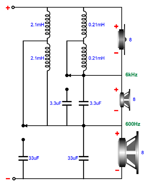
All the reactive values have halved, so the crossover frequencies have doubled. A two-pole, two-position switch is needed, possibly a toggle switch with hard-gold-plated contacts. Note that all the drivers remain phased the same way.
Making shifting crossover slopes is a bit trickier. Indeed, many would imagine the task near impossible to achieve, without building two separate crossovers and switching the drivers to one or the other. Such an brute-force approach would work, but it's not sneaky. The best 2nd-order crossover alignment is the Linkwitz-Riley, which sums to a flat frequency response. Let's look at a two-way Linkwitz-Riley crossover.
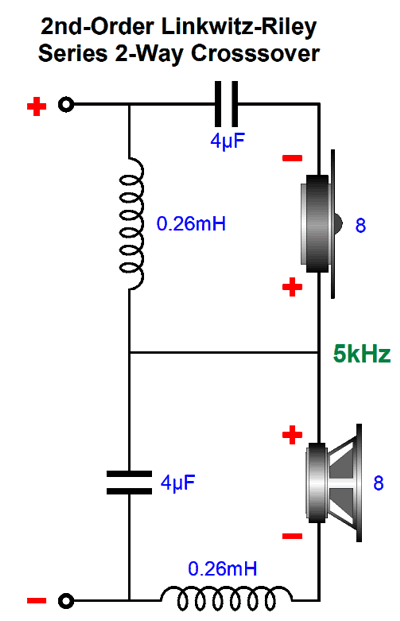
Once again, no bi-wiring is possible, as the crossover is in the series configuration. The alternative parallel arrangement could have been used, but it works best with current-out amplifiers, while the series arrangement works best with voltage-out amplifiers. In addition, the series arrangement is far more tolerant of part value discrepancies, such as a 3.3µF capacitor actually holding 3.7µF worth of capacitance. Since the 2nd-order crossover produces 180-degrees of phase shift at the crossover frequency between the two drivers, the tweeter's phase must be flipped. The Linkwitz-Riley crossover suffers from being a non-flat load impedance to the power amplifier. The workaround is to use my impedance-flattening network.
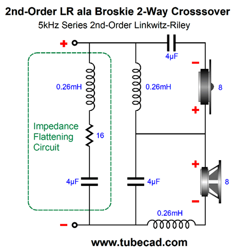
The 16-ohm resistor will get warm, but the power amplifier sees an 8-ohm load. Missing from all the schematics are Zobel networks for the woofers and midrange drivers. They must be used and were only left out to aid clarity. Let's now look at a 1st-order crossover at the same 5kHz crossover frequency.
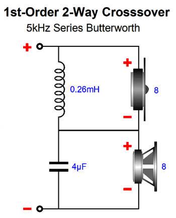
Note that the part values remain the same. Nice. (The parallel Linkwitz-Riley crossover uses different math, so the values are not the same.) This means that we only need to subtract parts, including the impedance-flattening network. In addition, we must un-flip the tweeter's phase.
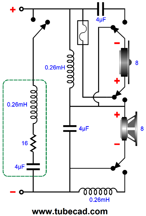
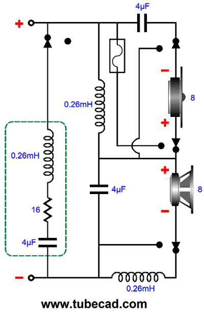
With the switch in this position, the crossover is a 1st-order type. The fuse is in series with the tweeter to provide added safety. (The unneeded 4µF capacitor could shunt the fuse.) We rotate the switch, and we get a Linkwitz-Riley 2nd-order crossover.
Providing the same shifting capability to a three-way Linkwitz-Riley crossover will be more complicated, but functionally the same. One major change is that we must flip the midrange phase not the tweeter's. My guess is that a six-pole, two-position rotary switch is all that is needed.
Yes, that is a lot of crossover parts, even more with the missing two Zobel networks added. To create the equivalent 1st-order three-way crossover requires much subtracting. Fortunately, we do not need to alter the remaining part values. Let's see if my guess was right.
It works, but it also requires seven-poles on the rotary switch. So, was my guess wrong? I had an intuition that only six poles were needed. While I do not completely trust my intuitions, I know better than to discount them. After staring at the schematic shown above, it came to me.
Only six poles are needed from the rotary switch. As I then stared at this revised schematic, I saw how only five poles were needed.
As far as I can see, this is the downward limit. We can even add a fuse in series with the tweeter in this setup, when in the 1st-order arrangement, which would be shunted by the 4µF capacitor. (Perhaps a self-healing plastic fuse could be used.)
Do either of these shifting arrangements make sense? I suppose that the answer depends on your temperament and perspective. My inclination is always to optimize in favor of more options, which definitely sets me apart, as most audiophiles—hell, most people—hate options. The greater the number of options, the greater is our responsibility in choosing the right option. Most car owners love automatic transmissions.
It's been ten years since I mentioned the following story, so it's due for a resurrection (expect to read it again in 2031).
Forgive me if I have mentioned this story before, but I once, over twenty years ago, was acquainted with this rich fellow, Roberto, who was a devoted audiophile. We weren't close friends as such, just acquaintances, for while I was able to tell him to his face that he was a fool, he didn't know me well enough to dare say the same to me. A fool? He owned four supremely fine audio systems, each costing close to six figures, each filled with cutting edge equipment, each absolutely identical. Yep, he had two identical systems in his big house and two identical systems in his two vacation homes. Every time he found a better phono cartridge or speaker cable or CD player, he would buy four of them, one for each identical system; the high-end audio stores loved him. His habit of buying four pieces of identical gear is why I called him fool.
I argued that he should build up four wildly different systems, each offering a different sonic perspective. One would be, say, a system that suited big classical recordings, one a system that made the best reproduction of a small jazz ensemble or string quartet, one that thundered and shook like a rock concert, and one that poured forth the most beguiling mono reproduction. He thought I was insane; his view was why should he ever listen to anything but the absolute best. "Best for what?" was always my counter question, but he never answered it beyond saying, "Just the best." Of course, one great advantage to being rich is that you can afford to be a fool or a madman or a drunk.... And after all, audio is a rich man's hobby.
By the way, when non-technically-minded friends ask what I write at the Tube CAD Journal, I send them the link to this post (number 216), as it is a fun read. (I am still waiting for the call from Anne's, Brad's, and Vinny's people.)

At classical music websites, I saw that Will Liverman and Jonathan King album, Whither Must I Wander, was making the best-albums-of-the-year lists. I found it at Amazon Music Service. Oh yeah, this is one fine album. The recording is first-rate and Will Liverman's baritone singing is exemplary. The Welch baritone singer, Bryn Terfel, now faces some strong competition from Liverman.
It's so easy to ham up or over emote a recital of classical songs, but Liverman delivers emotion without ever crossing over into melodrama. Jonathan Kin's piano playing perfectly matches Liverman's singing. That theirs is a debut recital makes this album even more impressive. (I would love to hear what they can do with Benjamin Britton's or Gerald Finzi's songs.)
//JRB
I met the great racing driver at a car show as young man. I noted that he was slightly irked by the shameful questions he was being asked. Shameful? Often, those asking want to show off, so they ask questions that they already know the answer to or questions which are so convoluted that we must imagine the questioner far cleverer than he is. He had received a series of such annoying questions. I rescued him by asking what car did he drive on the street; and did he enjoy driving off track. He went into a long description of his beloved Italian car and those occasions when driving off track was enjoyable.
Did you get your money's worth with this post by me? If so, think about supporting me at Patreon.

  
Just click on any of the above images to download a PDF of the user guides.

For those of you who still have old computers running Windows XP (32-bit) or any other Windows 32-bit OS, I have setup the download availability of my old old standards: Tube CAD, SE Amp CAD, and Audio Gadgets. The downloads are at the GlassWare-Yahoo store and the price is only $9.95 for each program.
http://glass-ware.stores.yahoo.net/adsoffromgla.html
So many have asked that I had to do it.
WARNING: THESE THREE PROGRAMS WILL NOT RUN UNDER VISTA 64-Bit or WINDOWS 7, 8, and 10 if the OS is not 32-bit or if the OS is 64-bit.
I do plan on remaking all of these programs into 64-bit versions, but it will be a huge ordeal, as programming requires vast chunks of noise-free time, something very rare with children running about. Ideally, I would love to come out with versions that run on iPads and Android-OS tablets.
|