| John Broskie's Guide to Tube Circuit Analysis & Design |
25 September 2021 Post 545
RMAF RIP
I feel both profoundly sad and relived. This means that many of the friends that I only see there I will never see again. The RMAF demise is sad and predictable. In fact, that was my prediction early this year. It just got too expensive for most exhibitors. The new venue was both beter and worse, far worse in the ways that count than the old hotel.
Vacuum Tubes Coming to Your Street?
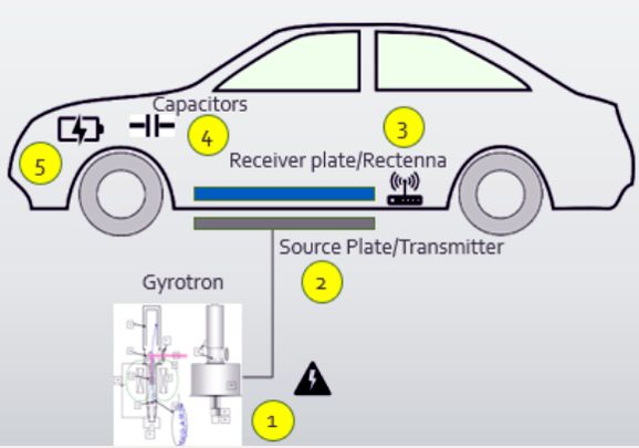
Under a recent proposal, many gyrotrons might be installed under road surfaces. Why? Electric vehicles (EV) hold huge batteries that must be charged, which is a pain, as the charging is slow, sometimes hours. Capacitors, on the other hand, can be charged in less than one second. The problem with capacitors is that they are relatively huge and hold relatively little potential energy. Yes, super-capacitors exist, but high-voltage super-capacitors do not. What if, however, every time you stopped at a red light or stop sign, your EV got a quick charge? The capacitor could then slowly replenish the battery and deliver power to the electric motor.
"Look Ma no wires." Visit the hyperfastcharge.com website for more details. What scares me is something going wrong, either by chance or malice. Do I want my gas-powered car to get accidentally blasted by 50 KW pulse of energy? No. Perhaps the car's metal body will function as a Faraday-shielded enclosure. Much experimentation and testing is needed. While on the topic of electric cars, long ago I read that a French car engineer had concluded that electric cars didn't make sense. Why not? Huge, heavy, and expensive batteries. In addition, the DC that charges the batteries incurs all the transmission and rectifier losses. DC voltage is not free, nor is it necessarily pollution free (electricity produced by burning oil or coal only displaces the pollution, not eliminate it). Moreover, a fully charged battery and a completely spent battery weigh the same. His alternative solution was compressed air. The car would hold a large air tank instead of a large battery and a pneumatic motor intead of an electric motor. The tank and engine are extremely low-tech and cheap, requiring no rare-earth elements in its construction. As the compressed air depletes, the weight of the car goes down, which improves the efficiency. In addition, we can exploit the fact that air at night is colder and thus denser than air at noon. (Moreover, cool air tends to be drier—it can’t hold as much moisture as warm air.) The air tank fills at night, but you drive during the hot part of the day. If I remember correctly, he actually built a car that ran on compressed air and the results were excellent. What about car accidents? Wouldn't the tank explode with force of dynamite? It could. Workarounds would be to make the bottom of the tank thinner than the top, so it would rupture down, not up. In addition, the equivalent of a bulletproof vest would shroud the top of the tank. Multiple small tanks could be used rather than one huge tank. In other words, workarounds are available. Moreover, batteries are also a huge hassle in a severe car crash, as they are filled with either acid and lead or exotic chemicals. Shorted batteries can explode, which is why even small batteries are now internally fused. (Remember the news stories about a cell phone batteries exploding or catching fire.) If something can store a vast amount of potential energy, it can also potentially release a great amount of energy suddenly.
Batteries are nowhere close to being perfectly efficient, as we must always charge at a higher voltage than what we will get out of the battery. In addition, batteries present an internal resistance and suffer from aging effects. What about the losses in compressing the air? AC motors just plug in the wall, so no rectification is needed. A small wind turbine could connect directly to a mechanical air compressor, no electronics involved. Gas stations could sell compressed air. Battery life isn't so much measured in years, but in charging cycles. For example, lithium-ion batteries can last for about 2,000 to 3,000 cycles. Air tanks can last centuries. Moreover, batteries are temperature sensitive, with high temperatures causing cathode-electrolyte oxidation, which can result in a sudden loss of capacity; and at temperatures below freezing, charging a lithium-ion battery will cause permanent SEI (solid electrolyte interphase layer) build-up on the anode, which both damages and reduces battery capacity. In contrast, an air tank is a simple thing that actually increases air pressure with increased temperatures. By the way, the air exhausted from the motor is cool, which means that it could be used to cool the inside of the car, once the air passed through a filter to remove any suspended lubricant particles. Another by the way, since a pneumatic motor runs cool, it will last far longer than a hot motor can; and it will not need a cooling system. In contrast, electric motors need to be significantly oversized—in power, size, and weight—to withstand high temperatures. Indeed, some of the air reserve could be used to blow cold air on hot disc brakes. In addition, we could brake the car by running a compressor to replenish the air tank. Remember, energy is always conserved, never destroyed, only transformed. The car's kinetic energy is transformed into heat by the disc brakes; it could be transformed into greater air pressure by running the motor backwards, transforming it into a compressor. Since rotary air motors exist, we could give each wheel its own air motor and achieve four-wheel drive. As you might guess, I have this idea some thought. Well, I did as a teenager, as I dreamt of making an air-powered bicycle. Where would I place the air tank? The frame would double as the air tank. Some young enterprising fellow should make not an Ebike, but an Airbike. The bike's air tank could be replenished at any gas station with tire inflating hoses and compressor.
Two-Triode Aikido Amplifier
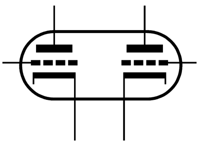
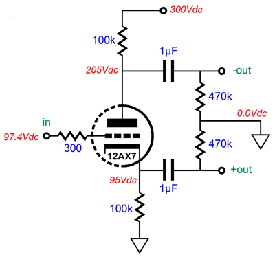
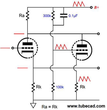
If we stop to think about it, we quickly see that the split-load phase splitter is simply a grounded-cathode amplifier whose unbypassed cathode resistor is so large in value that no signal gain is achieved. In addition, since the plate and cathode resistors share the same value, they must see the exact same voltage drops and they are both in the single current path from ground to the B+ voltage. As the triode undergoes a varying current flow due to the varying signal voltage at its grid, the plate and cathode resistors produce equal magnitude—but out of phase—output signals. Thus, in terms of output-signal balance, no phase splitter beats the split-load phase splitter. In terms of PSRR, however, we see a different story. The triode's plate impedance in a grounded-cathode amplifier circuit depends on the triode's plate resistance and the unbypassed cathode resistor value. The formula is a simple one: Z = rp + (mu + 1)Rk where mu is the triode's amplification factor; rp, the plate resistance. The formula reveals that the cathode will magnify the cathode resistor value by mu + 1, so a 10k cathode resistor will effectively become a mu + 1 larger impedance. For example, a 6DJ8 offers a mu of about 33, so the triode's plate impedance with a 10k cathode resistor will equal 3k + (33 + 1)10k or 343k. This impedance in series with the 10k plate resistor forms a two-resistor voltage divider with the power-supply noise, so we can expect a 343k/(342k + 10k) attenuation or 343k/352k or 0.974, which equals -0.22dB. Not much at all. Mind you, in some circuits, the poor PSRR can prove an advantage; in most power amplifiers, however, it is a big liability. My workaround was to use a second triode to eliminate the power-supply noise for the inverting output of the split-load phase splitter.
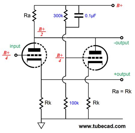
The second triode's input signal is the power-supply noise. As the power-supply noise goes positive, the second triode's current conduction increases, pulling the plate voltage downwards, creating a power-supply-noise null against the upward pull of the power-supply noise. Conversely, when the power-supply noise goes negative, the second triode's current conduction decreases, releasing the plate voltage upwards, once again creating a power-supply-noise null against the downward drop of the power-supply noise. This is not an example of negative feedback, where something goes wrong and the circuit tries to correct it after the fact. This is an example of proactive feedforward anticipation of something going wrong and fixing it as it happens.
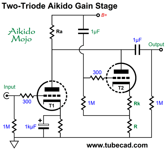
The Broskie phase splitter's two outputs enjoy a high PSRR. The downside to the Broskie split-load phase splitter is that it requires more parts and that it offers smaller output voltage swings. The latter failing can prove a problem in a push-pull power amplifier, depending on the phase splitter's location in the amplifier circuit. If it comes early, it probably won't be an issue; if it come late, it probably will be. Well, this got me thinking: what if we didn't need balanced output signals nor big output voltage swings (for example, a line-stage amplifier), couldn't this split-load phase splitter be transformed into a line-stage amplifier? Indeed, it can. I have produced many two-triode Aikido mojo gain circuits; for example, post 432 holds a few. In fact, one of the circuits uses the same functioning.
Both triodes share the same cathode resistor value and, thus, idle at the same current flow. The power-supply noise is sampled by the two-resistor voltage divider and a fraction of the power-supply noise is injected into the second triode's grid. The split-load phase splitter inspired variation applies 100% of the power-supply noise to the grid.
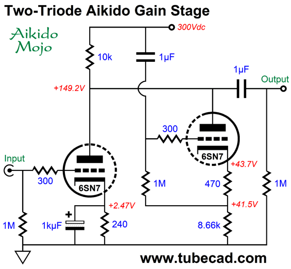
The input triode's cathode resistor is purposely bypassed, as it will improve the PSRR and offer a lower output impedance (in addition, it will promote a stronger 2nd harmonic distortion). The input triode draws about 10mA, while the Aikido mojo triode draws about 5mA. The shared plate resistor thus sees 15mA of current flow, which will produce i²R or 2.25W amount of heat. (I would use four 1W 10k resistor in series-parallel to effectively create a 4W 10k resistor.) Here is a design example based on the 6SN7.
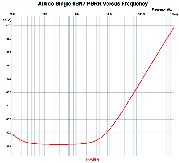
So how well does this 6SN7-based line-stage amplifier perform? The PSRR in SPICE simulation was better than -60dB at 100Hz.
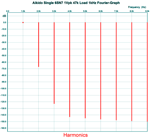
Nothing to worry about here, especially when we consider that this is raw PSRR. If we add a simple RC power-supply filter to the B+ voltage, the power-supply noise will diminish hugely. In terms of harmonic distortion, the circuit performs admirably well.
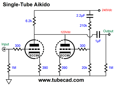
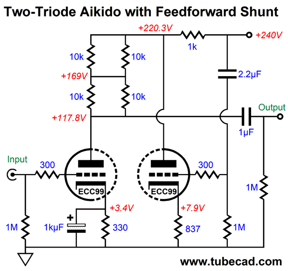
As you can see, most of the 0.1% THD is located in the second harmonic, which is just what we want from a tube-based line-stage amplifier. Yes, this circuit requires two triodes, whereas a single triode could be used with a regulated B+ voltage. In other words, I have shifted some of the complexity away from the power supply to the line-stage amplifier. I do like that each channel gets its own 6SN7 tube. I would further and give each 6SN7 its own heater power supply. Actually, I would use either an NOS 12SN7 or 12SX7 or a new-production ECC99, as a 12V heater regulator is a much better option than a 6.3V regulator, due to rectifier losses, regulator voltage drop, and doubled current flows. While on the topic of two-triode Aikido gain stages, post 486 showed an ECC99-based variation that used a feed-forward shunting power-supply noise filter.
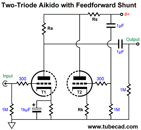
We can add a bypass capacitor to the input triode's cathode resistor, but not the shunt-regulator triode, as we need to weaken the shunt triode's transconductance to match the series resistor, Rs. In other words, if we did shunt the cathode resistor, the triode will retain all its transconductance, which would necessitate a much smaller resistance value of the series resistors.
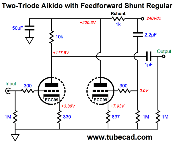
Let's use an ECC99 in a design example.
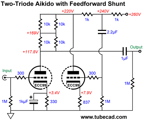
The 1k series resistor that connects to the B+ voltage is matched to the ECC99 without bypass capacitor. If we did add a bypass capacitor, we would have to decrease the series resistor value. This brings up an interesting application tip; once we have established a match between the shunting triode's transconductance and the series resistor's value, we can add another resistor in front of the original Rs resistor as long as the 2.2µF capacitor remains were it is. For example, say the raw B+ voltage was 260Vdc, not 240Vdc, we could add another 1k series resistor and still obtain the feed-forward shunting effect.
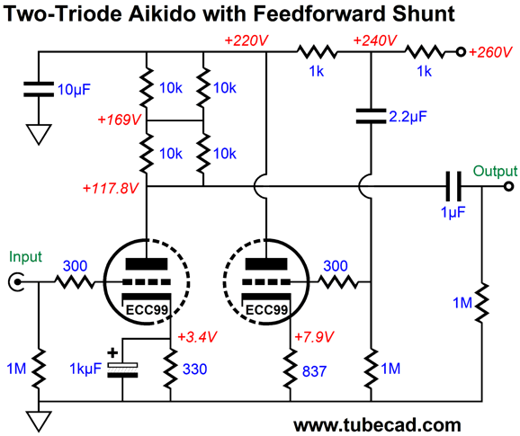
We can even add an additional capacitor.
Note that the 2.2µF capacitor still relays the greatly-reduced power-supply noise at the connection between series resistors to the shunting triode below. If we terminate this capacitor at the raw B+ voltage, we get a far worse PSRR. If we eliminate the capacitor altogether, we also get a worse PSRR. Think about this: if we match the series resistor (Rs) value exactly with the shunting triode's transconductance inverse, we could achieve a near infinite PSRR. In contrast, simple shunt regulator based negative feedback taken from shunting triode's plate can never yield so great a PSRR. Moreover, an RC filter could only achieve similar results by either using a huge series resistor value or shunting capacitor value (or both).
Bowers & Wilkins PI3 (I actually knew one-eyed Jack O'Neill, when I lived 30 years ago in Santa Cruz, California. I thought he was old then—and he was, as he was born in 1923 and was a Navy pilot during WWII. He was also a born character. When you have enough cash, you are not only allowed to be an eccentric, but encouraged. My favorite quote that I have seen attributed to him is, "I'd like to apologize in advance for anything I may say or do that could be construed as offensive as I slowly go nuts!" Sadly, he died in 2017, but perhaps that is just as well, as he missed seeing how we have considerably surpassed him, having gone even more nuts than he could imagine.) Eventually, I gave up on any wired earbuds and switched to Bluetooth-connected earbuds. I have owned at least five of these. The huge problem I have is that they always fall out of my ears, bounce across the sidewalk and die. I need a pair with tethered earpieces. While at Costco, I spotted the B & W PI3—which list for $199 and sell for over a hundred at Amazon—for only $59.97. A quick scan of its specifications revealed that they supported the AptX-HD codec and USB-C charging. In addition, the earbuds connect as a single entity to the Bluetooth transmitter, so the pain of broken syncing, where only one earbud connects, is sidestepped. Okay, that was enough for me (additionally, I had a vague memory of hearing other B & W earbuds and liking them, possibly at an RMAF Can-Jam). Punch line: they sound good, amazingly so. They actually image! At startup, a pleasant female voice in a soothing English accent says, "Connected." They lack the deep bass of my HiFiMan planar headphones, but then so do all other earbuds. The bass the PI3 produces is well defined, tight, and, dare I say it, punchy. Jazz sounds great with them. I needed them, however, primarily to listen to spoken word recordings and podcasts, a seemingly humbler task, but actually one that requires great midrange articulation. Upon opening the package, I saw that the PI3 earbuds are far more interesting than I expected them to be. First, they hold 24-bit, 96kHz DACs and they are bi-ampped. Each earbud holds two tiny drivers, with each driver getting its own power amplifier. I am sure that the main reason these earbuds deliver such clean midrange is due to the two-way design. Freed from the onerous task of reproducing deep bass, the high-frequency driver has a much easier time. Given that the distance between the two drivers is about a quarter of an inch (6mm), a crossover frequency of 500Hz would be no problem, as the wavelength of a 500Hz sine-wave in air is 27 inches. For the last two or three years, I have been convinced that bi-ammped two-way drivers was the future for high-end headphones in general. Active crossover filters and two power amplifiers are essential, as a passive crossover would require huge inductors due to the high 32-ohm impedance. Bi-ampping sidesteps this problem. In addition, the bass amplifier can clip, but as long as the high-frequency amplifier does not, you probably won't hear it. I am going to go out of my way to take care of these earbuds, as I am so impressed with the sound. Bravo Bowers & Wilkins, a job well done
Combining Series and Shunt Regulators
Let's imagine a robust line-stage amplifier that held one triode-connected EL84 per channel in a grounded-cathode amplifier configuration. Let's also imagine an idle current draw of 20mA and plate load resistor value of 5k. The B+ voltage is 300Vdc and the external load impedance (the power amplifier's input impedance) is a low 20k. Further, let's imagine that 10V of peak output voltage swing is required to drive the amplifier to full output, which is a crazy big voltage swing. In spite of the big output, the required current swings are relatively modest, being only 2.5mA peak. Assuming stereo playback, we are facing only a 5mA potential peak current swing. This 5mA peak swing is all that the shunt regulator needs to correct; thus, we could be generous and let the shunt regulator idle at 10mA. In contrast, a series regulator would see a fairly constant current draw that idled at 40mA and peaked at 45mA and dropped to a low of 35mA.
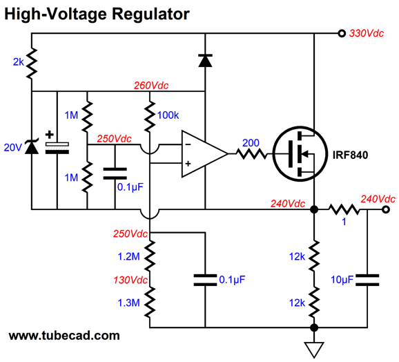
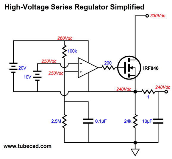
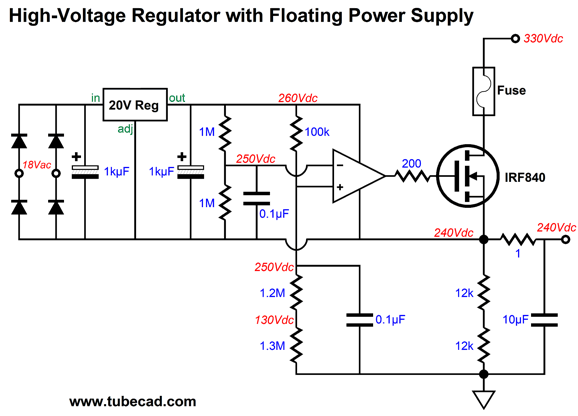
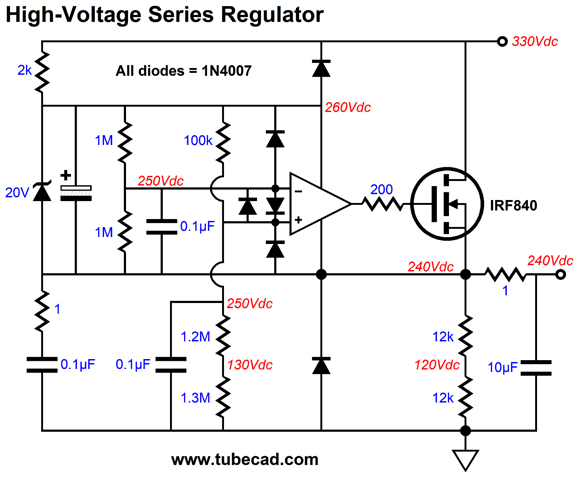
What if we combined both regulator types? The series regulator would still idle at 40mA, while the shunt regulator could idle at 10mA. Do not be surprised by the shunt regulator's dissipation exceeding the series regulator's. For example, let's say that the raw B+ voltage is 330Vdc and the regulated DC output is 280Vdc. The series regulator's pass device sees a 50V voltage drop, which against its 40mA idle current equals 2W of heat dissipation. In contrast, the shunt regulator's pass device sees 280V voltage drop, which against its 10mA idle current equals 2.8W of heat dissipation. What sent me down this rabbit hole was a high-voltage series regulator that I had designed that stalled in SPICE simulations without an output resistor to shield the regulator from the shunting capacitor. The OpAmp controls the MOSFET's output and sets the DC output voltage through the two-resistor string of 1.2M and 1.3M resistors. The OpAmp's 20-volt power supply is derived from the zener diode and the B+ voltage through the two 12k resistors in series. The zener also doubles a the regulators voltage reference The 1-ohm series resistor made the SPICE engine happy. Here is a simplified version that uses batteries to power the OpAmp and provide a voltage reference
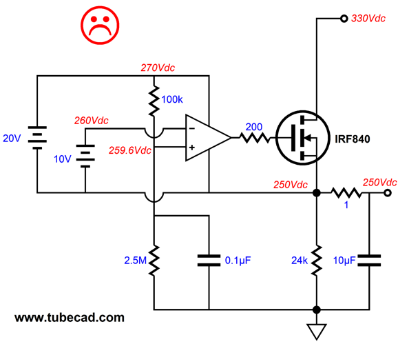
At all times the OpAmp strive to keep its two inputs at the exact same voltage. The only way this condition can be met is for the output voltage to be 240Vdc, as that would force a 250V voltage drop across the 2.5M resistor and 250V at the OpAmp's inverting input. Let's say the output voltage climbed to 250Vdc.
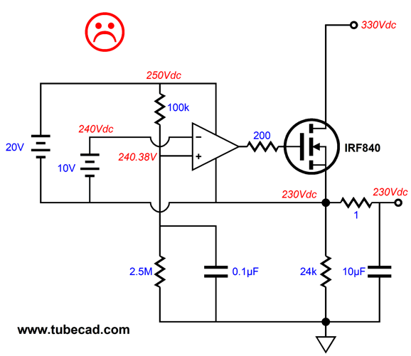
The OpAmp's non-inverting input sees less voltage potential than its inverting input, so the OpAmp's output swings negatively, decreasing the MOSFET's current conduction, until the two inputs are brought back into line with each other, which happens at 240Vdc. If the output voltage fell to 230Vdc, the non-inverting input would see a 0.38V higher voltage than the inverting input, which would force the output up in voltage, further turning on the MOSFET, causing the output to climb back up to 240Vdc. Now, 0.38V may not seem like much of a voltage discrepancy, but we must remember that the OpAmp's open-loop DC gain is fantastically huge, as in 100dB (1 to 100,000).
This is how negative feedback works in the series regulator. I know some will find the batteries mentally disconcerting, so here is a version that uses a 18Vac secondary to to establish the needed OpAmp power supply.
I prefer this arrangement, as it is more efficient. Okay, lets look at the deluxe version of this series regulator.
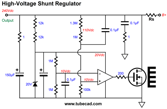
As I look over the schematic I see three items of potential discontent: the 2k resistor that relays the current from the B+ voltage to the zener diode and OpAmp, the 1-ohm output resistor, and the two 12k load resistors. The 2k and 12k resistors could be replaced by constant-current sources, which would increase the regulators minimum B+ voltage requirement, i.e. its drop-out voltage. The output resistor falls outside the negative feedback loop, so it worsens the output impedance. My natural way of thinking is to hunt for ways to turn liabilities (bugs) into features. In this design, the two 12k resistors provide the needed current flow to keep the OpAmp and zener happy. Well, what if moved the resistor to the other side of the 1-ohm output resistor? The same DC current path would obtain. Now, what if we replaced the two resistors with a shunt regulator that also idled at 10mA? The 1-ohm resistor would become the shunt regulator's series resistor; in fact, we could increase its value to 100 ohms or more. But before I get ahead of myself, let's look at solid-state high-voltage shunt regulator.
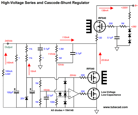
The next step is to combine the two types of regulators.
The series regulator is a simple capacitance-multiplier circuit to further clarity, but it could be replaced with the OpAmp-based series regulator. (And, yes, I did sneak in the needed protection diodes.) The cascode topology allows us to use a low-voltage, low-capacitance MOSFET on the bottom. In SPICE simulations, the circuit delivered a PSRR of over -180dB at 100Hz. Mercy!
Randall Jarrell
It goes on for several pages. What do you think? I am shocked how well the translation works.
Music Recommendation: Penguin Cafe's Handfuls of Night
Their music defies easy classification, being an interesting hybrid of folk, electronic, new-age, and classical. No matter which genre it falls into, the music is dang pleasurable to hear. I noticed that Amazon Music offered their latest album, Handfuls of Night, in 24-bit, 96kHz flac format. Give it a listen. Then give their Handfuls of Night (Explored) album a listen, which not so much explores the tracks, but explicates them through a brief audio commentary before the music track plays.
//JRB
Very few can imagine just how much hard work is required to make one of my posts. If you have any sort of inkling or intuition of what is involved, please think about supporting me at Patreon.
User Guides for GlassWare Software
For those of you who still have old computers running Windows XP (32-bit) or any other Windows 32-bit OS, I have setup the download availability of my old old standards: Tube CAD, SE Amp CAD, and Audio Gadgets. The downloads are at the GlassWare-Yahoo store and the price is only $9.95 for each program. http://glass-ware.stores.yahoo.net/adsoffromgla.html So many have asked that I had to do it. WARNING: THESE THREE PROGRAMS WILL NOT RUN UNDER VISTA 64-Bit or WINDOWS 7 & 8 & 10 or any other 64-bit OS. I do plan on remaking all of these programs into 64-bit versions, but it will be a huge ordeal, as programming requires vast chunks of noise-free time, something very rare with children running about. Ideally, I would love to come out with versions that run on iPads and Android-OS tablets.
//JRB |
|
I know that some readers wish to avoid Patreon, so here is a PayPal button instead. Thanks. John Broskie John Gives
Special Thanks to the Special 87 To all my patrons, all 81 of them, thank you all again. I want to especially thank
I am truly stunned and appreciative of their support. In addition I want to thank the following patrons:
All of your support makes a big difference. I would love to arrive at the point where creating my posts was my top priority of the day, not something that I have to steal time from other obligations to do. The more support I get, the higher up these posts move up in deserving attention.
Only $12.95 TCJ My-Stock DB
Version 2 Improvements *User definable Download for www.glass-ware.com |
||
| www.tubecad.com Copyright © 1999-2021 GlassWare All Rights Reserved |





%20Cover.jpg)


