| John Broskie's Guide to Tube Circuit Analysis & Design |
17 November 2021 Post 548
Sneaking Aikido Mojo Into a Regulator
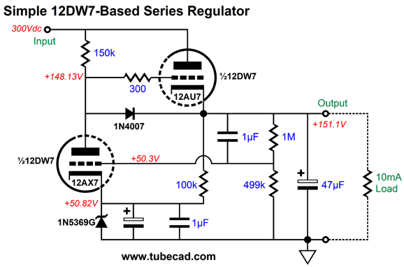
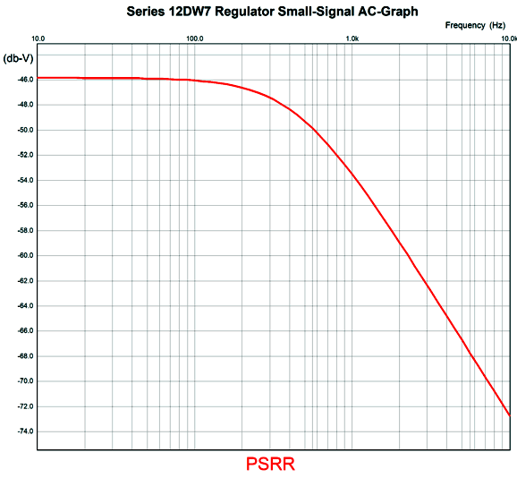
The 12AU7 triode works as the pass device, while the 12AX7 functions as the negative feedback device and the zener serves as the voltage reference. The 1M and 499k resistors set the regulator's DC output voltage, while the 1µF capacitor shunting the 1M resistor provides 100% negative feedback of high-frequencies, as those above 0.2Hz. The regulator's PSRR is a fair -46dB at 100Hz.
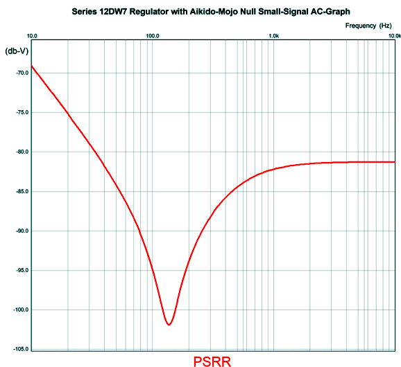
The 62µF output capacitor imposes a -3dB transition frequency occurs at 457Hz. Considering the triode's weak transconductance, the resulting performance is somewhat impressive. To make it truly impressive we need to inject some Aikido mojo.
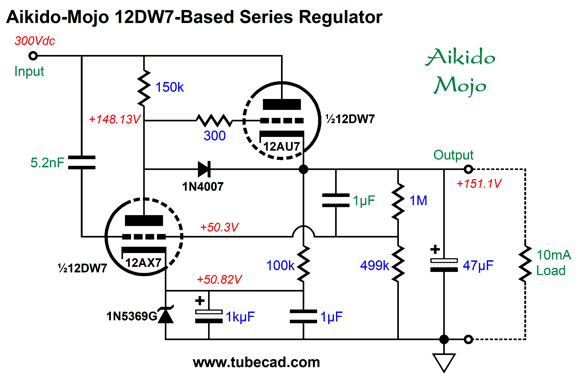
The added 5.2nF capacitor leaks a small trickle of the raw power-supply noise into the 12AX7's grid, about 0.5% worth. What this miniscule amount of ripple does is provoke a countervailing of current flow that creates a deep PSRR null. How deep? This deep:
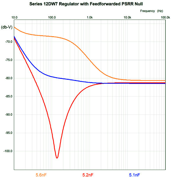
That is an amazingly deep null, but it requires precise capacitor values. How precise? Very precise. Here is a graph that shows three values for the added capacitor, 5.1nF, 5.2nF, and 5.6nF.
The problem is that 5.2nF is not a commonly available capacitor value, whereas 5.1nF and 5.6nF are. The workaround is to place a 3nF capacitor in parallel with a 2.2nF capacitor. In addition, this assumes that the 1µF capacitor shunts the 1M negative feedback resistor. If a different value does, say 0.82µF or 1.2µF, the deep null won't obtain. Making the problem even thornier, film capacitors often come in 10% tolerances and there is little assurance that the triode exactly conform to the tube manual specifications. The result is that two different HiFi hobbyist build this circuit, but one gets an amazing flow of audiophile superlatives, such as fluid, black spaces, ultra-detailed, whereas the other gets just okay. The only solution, actually, is to test the circuit with an oscilloscope. Few own a scope, and fewer know how to use it properly. Nonetheless, after the voltmeter, the oscilloscope is essential to exploring and modifying audio equipment, as it allows us to see what is going on in a circuit. When testing a high-voltage regulator, especially one that offers excellent performance, I replace the existing raw power-supply reservoir capacitor, say a 150µF capacitor with one of vastly lower capacitance, say 3µF. Why? I want the ripple to increase dramatically, which allows me to see better how well the regulator rejects the power-supply noise. For example, -80dB attenuation means a 1/10,000 reduction. Instead of trying to measure the reduction in 0.1V of ripple, I measure the reduction of 10V of ripple, which is 100 times bigger on the scope trace. With such a setup, it is fairly easy to start with lower capacitor value, say 4.7nF, and then tack solder smaller capacitor value in parallel with it until the deep null is achieved. Then, either I solder all the capacitors tightly together or I measure their combined value and replace it with a single capacitor, if possible.
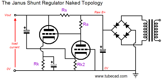
Hybrid Janus Regulator
The tube used was a 12DW7/ECC832/7247, which holds dissimilar triodes, one 12AU7 and one 12AX7 type. The 12AX7 triode drives the 12AU7's grid and the 12AX7 plate resistor leaks enough of the raw DC power-supply ripple to null it at the 12AU7's plate. The 12AX7 is configured as grounded-grid amplifier, which means that the input signal appears at its cathode, not at its grid, which explains why a large-valued capacitor is used to relay the AC signal at the output to the cathode. The result is that whatever unwanted AC signal appears at the output gets greatly amplified at the 12AX7 plate. Of course, the 12AX7 offers only fraction of the gain that solid-state devices can yield; thus, the temptation to introduce a hybrid element.
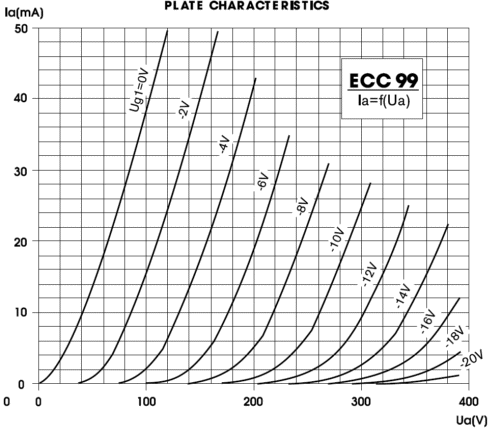
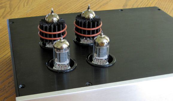
A much more robust twin-triode tube is the ECC99, with 5W plates. Placing two of its triodes in parallel allows us to both increase the current flow and not lose too much voltage across the series resistor, as this resistor must equal the inversion the triode's transconductance, which two doubles, which in turn halves the resistor value.
Okay, let's see the simple circuit fleshed out.
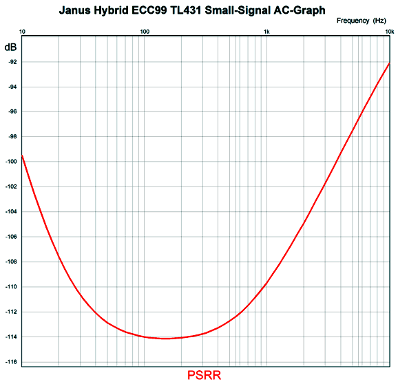
The MJE350 PNP transistors are 300V devices, which is not needed, as low-voltage transistors could be used. I just happen to own a bunch of the MJE350, so I use them everywhere. Three zeners were added. The 100V zener is there to limit the ECC99 triodes' dissipation, as the zener must dissipate 1.8W. The other zeners offer protection for the TL431. How well does the regulator work?
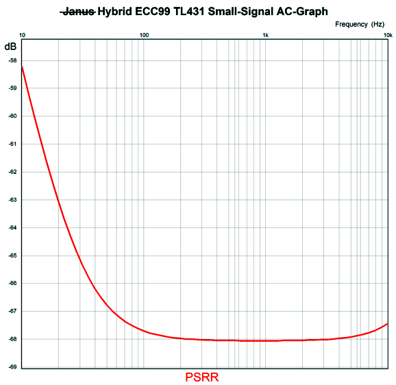
Not bad. Note the -114dB at 120Hz. What if we subtract the Janus feedforward portion of the circuit? The way we do this is to simply ground the two grids. The DC output voltage remains the same, but the AC results differ markedly. Here is the result.
Not nearly as good. Okay, since the number of circuits that can pour out of my mind seems boundless, I will stop with the following variation.
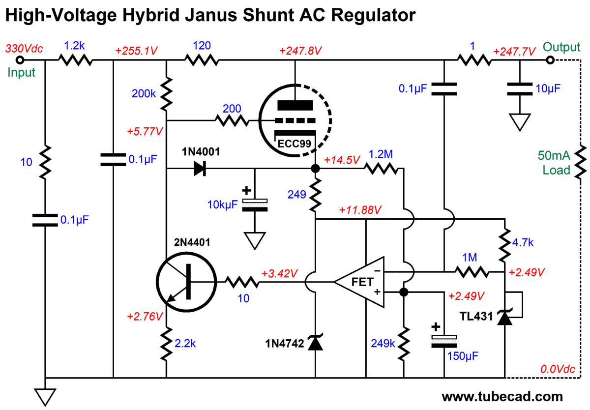
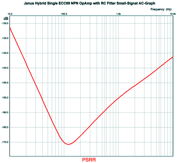
The motivation behind this variation is a distrust of the TL431/LM431 shunt regulator IC. No doubt is is very good at what it does, but there is no way that its simple internal OpAmp can match the performance of a high-performance OpAmp. If nothing else, the TL431's internal OpAmp does not hold a FET input stage, which would allow us to use much larger-valued resistors and low-valued capacitors. Much like the original Janus regulator, this hybrid regulator does not regulate the DC output voltage, only the AC portion. It does, however, auto-bias the ECC99 triode's idle current through the 1.2M and 249k resistors. The TL431 is used as a voltage reference. The 2N4401 NPN transistor is configured as a common-emitter amplifier, so the OpAmp's output signal is further amplified and phase inverted. The result is much higher gain to fuel the negative feedback. How well does it work?
Finally!
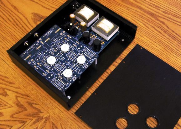
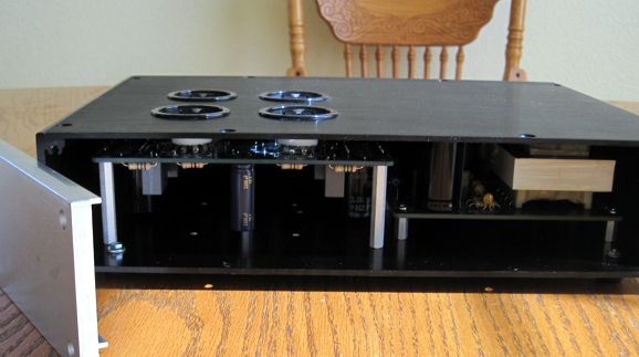
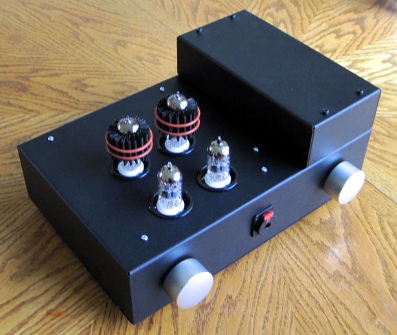
Sadly, I never finished the project. Why not? Nothing is more difficult than finishing a stalled project. The psychic weight is just too great, crushing your spirit with just the thought of starting again. In this example, the front faceplate was too thick for my cheap drill press, so the project languishes in a closet.
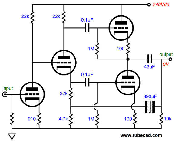
Finishing the project, however, was never the real goal; listening to headphones with a current-output amplifier was and is still the desired goal. Once, however, I did get to hear such a headphone amplifier at one of the Can-Jam events at an RMAF; sadly, the headphones were entirely unworthy of the experiment, so bad that I do not accept that listening experience as counting. So what has changed? Why was I tempted to exceed my exclamation-point allotment? Today I was listening to one of my favorite tube-based headphone amplifiers, which I revealed in post 503 last year. It differs from other OTL tube-based headphone amplifier in that both output tubes functions as grounded-cathode amplifiers, not cathode followers, so the output impedance is far higher than the equivalent cathode-follower output stage. In addition, no negative feedback loop is used, further increasing the output impedance. Moreover, the cathode resistors are not bypassed with any capacitance, further increasing the output impedance. In short, this is a high-Zo headphone amplifier.
Since, my daughter was using my 300-ohm Sennheiser HD650s, I plugged in my HiFiMan planar HE400i headphones instead—a seemingly bad idea, as the load resistance (35 ohms) is far too low for the 43µF output coupling capacitors, which implies a -3dB low-frequency cutoff frequency of 106Hz. Yet, I heard deep bass and far more SPL than I imagined possible. What is going on here?
The short answer is that the 35 ohms must be added to the high output impedance of about 630 ohms, so the real -3dB low-frequency cutoff frequency is far lower. At the same time, the damping factor is dismal, as the output impedance is twenty times higher than the load impedance. With most headphones this can be a problem, but not with a planar headphone with a flat impedance. In other words, the bass didn't go all wobbly. Another unexpected result was that the headphones played loud enough, which I didn't expect based on the 22mA of output stage idle current, which implies just 1.5Vpk of class-A output, which further implies 35mW of power into 35 ohms. The headphone's rated sensitivity is 93dB with 1mW. If I haven't messed up on the math, 109dB is maximum SPL with this headphone amplifier in class-A operation. Of course, we can drive the output stage beyond its class-A window of operation, but the signal suffers. The amazing thing was the increase in delicacy and air, which approached what my Stax electrostatic headphones deliver, but with better bass. I know the next sentence will sound crazy. The silence is now pregnant with significance. As the musicians pause, they still seem present. I have heard this sonic magic only a few times, maybe three times and only with insanely expensive stereo systems. The saxophonist stops blowing, but he hasn't left the room, as his presence is still felt, perhaps we still hear his faint breathing or fidgeting. Whatever the cause, the effect is riveting. Well, I experienced this unexpected sensation with this high-Z headphone amplifier, which comes close to providing current output. I was so taken by the result that I listened to one of my favorite albums, Bloom, by Areni Agbabian, twice in a row.
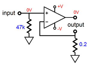
Has this happy accident motivated to finish my partially-built, current-output headphone amplifier? It just might, but I will run into a snag. Current-output requires a balanced output signal, as we must place a resistor in series with the headphone driver's negative input terminal. In other words, the shared ground is gone, as each channel gets its own current-sense resistor.
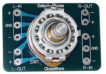
As you can see, the output no longer terminates into ground. This requires an XLR or other type of balanced headphone jack, which in turn requires replacing the existing headphone cords. It's doable, but a pain nonetheless. On the other hand, balanced output allows us to select easily the desired phased output with a rotary switch.
The mute in the center position is an essential and desired feature. I promise you that if you flip the phase back and forth with a toggle switch, you will hear zero difference. In contrast, if you pause at mute for just a second or two, then the inversion will be quite apparent, as your brain has time to reset. Moreover, if the phone rings or your dog begins barking wildly, it's a great feature to be able to apply a quick hard mute. Returning to my high-Z headphone amplifier, why does it sound good in spite of the high output impedance? As I see it, the planar headphone drivers are absolutely indifferent to the output mode, be it voltage or current. The output tubes, on the other hand, only provide their plate resistance as the single negative feedback mechanism. In other words, unlike a cathode-follower output stage, the grounded-cathode-amplifier output stage is far less sensitive to load impedance or output signal; and, as a consequence, far less in control of the output signal in term of voltage, but not curent. Possibly, the output triodes, freed from negative feedback duties, just respond to the input signal at their grids, swinging more or less current in response. Not very cogent, I admit. Whatever the actual cause, I do know that I like the result.
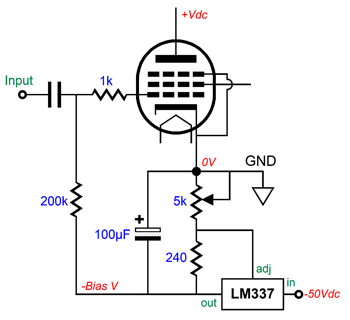
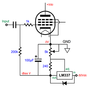
Regulated Fixed-Bias
Since the LM337 hold an internal voltage reference, the bias is not only ripple-free, but also fixed in DC voltage. One thing to note is that the LM337 is rated for only -37V, but his raw negative power-supply rail supplies -50Vdc. (Long ago, they made a high-voltage version of the LM337, LM337-HV, that was rated for -47V.) We could shunt the regulator with a 36V zener as a safety measure.
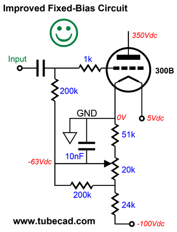
But the real question to ask is, Should we regulate the negative fixed-bias grid voltages? Thirty years ago, a super famous tube-audio company told me that they were adding regulated fixed-bias to their power amplifiers. I explained that it wasn't a good idea. Why not? It can be a good idea, if and only if the B+ voltage is also regulated or if the output stage runs in strict class-A, otherwise the regulated fixed bias was counterproductive. How so? The power amplifier's B+ voltage at idle might 470Vdc, but at full output it most certainly will sag, say to 400Vdc, if not more. Why? The power transformer's primary and secondary present DC resistance (along with the choke DCR), which against the far greater current draw will force a greater voltage drop, which can only subtract from the B+ voltage. (This also happens in solid-state power amplifiers that are run in class-B.) When this happens, the fixed-bias voltage will be too great with voltage regulation. In other words, the output tubes need less negative bias voltage with the reduction of B+ voltage. Here is an example with a 300B triode. Let's say the idle B+ voltage is 330Vdc and the negative bias voltage is -63Vdc, which results in about 95mA of idle current flow. If the B+ voltage sags by 10%, the idle current falls to 50mA with the -63Vdc of bias voltage, which results in a plate dissipation of only 15W, versus the idle dissipation of 31.4W. (See post 348 for the constant-dissipation alternative.)
In contrast, if the negative-bias power-supply rail voltage is allowed also to sag with the B+ voltage, the idle current will remain largely unaltered. For example, if the B+ voltage dropped from 330Vdc to 300Vdc, the negative-bias voltage would also drop from -63V to -57.3V, which results in a plate dissipation of 24.8W, versus the idle dissipation of 31.4W. Moreover, in case of an over voltage at the wall socket, the negative bias will drop further negatively, thereby preventing the gross excessive dissipation of the regulated fixed bias option. By the way, this assumes the negative-bias voltage was derived from a tap on the secondary.
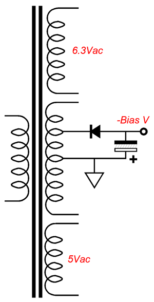
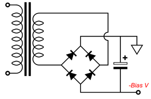
This is the old-school way of establishing a low-current, negative-voltage power-supply rail. Long ago, solid-state rectifiers were expensive, so half-wave rectification was used, as only one expensive-at-the-time solid-state rectifier was needed. In general, half-wave rectification is a bad idea, as the unidirectional current pulses tend to magnetize the transformer core. Fortunately, we need very little current in the negative-bias circuit. The alternative approach uses a separate power transformer for developing the negative-bias voltage, which is usually full-wave rectified. This power-supply rail will not collapse in voltage when the output stage is driven to full output, so it is form of regulation lite.
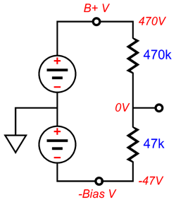
A new problem is that the B+ voltage reservoir capacitor will deplete far faster than the negative-bias reservoir capacitor, assuming a large-valued capacitor is used. The test I performed decades ago was to place a two-resistor voltage divider spanning across the B+ voltage to the negative-bias voltage. The connection between resistors should be 0Vdc at idle and at full output.
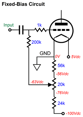
My test was to bring the amplifier to full output with tone bursts, while monitoring the voltage at the resistors nexus. I started with a purposely low-valued bias capacitor and then tack soldered on more capacitance until both reservoir capacitors depleted in unison. In other words, using whatever large-valued capacitor you have for the negative-bias circuit is sub-optimal. While on the topic of fixed negative-bias circuits, here is a typical setup.
The potentiometer sits between two resistors, which allows for finer bias-voltage adjustments. Everything looks good, but a potential problem exists. How often do you make an adjustment to the bias potentiometers? Not that often; once when you replace the output tubes and maybe once again in a year or two. This means that the potentiometer does not see a lot of use and, as a result, the scrapper can lose its secure contact with the resistive wire or trace. Not good, as the output tube loses its negative grid bias and the tube can go into melt-down.
(Back in the days of TV repair, a common problem was old-lady switching, where an elderly woman gently rotated the volume and station knobs, which prevented their self-cleaning action, resulting in poor contacts. In contrast, TVs under the control of young kids saw intense and aggressive knob twirling, which kept the scrapper and switch contacts clean.) My workaround to the problem of lost bias voltage is to add an extra safety resistor.
If the potentiometer scraper breaks contact, the safety resistor will pull the bias more negative, so the output tube decreases its current conduction.
Music Recommendation: Composition Transcriptions
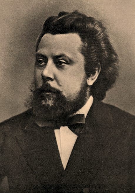
Modest Mussorgsky was a mega Russian composer (1839 – 1881), whose compositions broke with the European mold and helped give birth to the distinctly Russian sound. His first name comes from the Latin word, "modestus," which means moderate or restrained, which alas he wasn't, sadly, being a famous drunk who died tragically early. His most famous composition is his piano suite Pictures at an Exhibition (in memory of Hartmann), which most have heard in orchestra transcription. The first transcription for orchestra was by a fellow Russian composer and conductor Mikhail Tushmalov. Then in 1915, British conductor Henry Wood made his version for orchestra, but retracted it upon hearing Maurice Ravel's version, which is now deemed the standard, but we do occasionally hear Leopold Stokowski version, which sought to restore the Russian flavor and undo the French accent that Ravel had instilled. (If you have never heard the original as a piano suite, I can recommend Paul Lewis's 2015 recording.) Well, quite by accident, I discovered an interesting new transcription by the brothers, Vivan and Ketan Bhatti, which they made for the German break-dancing group, Flying Steps, and which fills the album, Flying Pictures At An Exhibition. Amazon Music streaming service offers this album in a 24-bit & 48kHz high-resolution format and it is sound fresh and dynamic.
I was so taken by listening to this album that I was reminded of enjoying as a teenager Franz Liszt's transcriptions of the Beethoven symphonies for piano. A quick hunt at Amazon Music uncovered several albums by Swiss-Russian pianist, Konstantin Scherbakov, all of which are delightful—all 5 hours and 45 minutes' worth! The transcriptions of the 4th and 6th symphonies are in a 24-bit & 44.1kHz high-resolution format. Scherbakov was a good choice, as his performances of the Beethoven piano sonatas are excellent.
The obvious temptation is to start with either the 5th or 9th symphony transcriptions, but I recommend the 6th, as it ideally suits the piano. (In fact, I was quite taken by the 2nd symphony transcription.)
//JRB
Very few can imagine just how much hard work is required to make one of my posts. If you have any sort of inkling or intuition of what is involved, please think about supporting me at Patreon.
User Guides for GlassWare Software
For those of you who still have old computers running Windows XP (32-bit) or any other Windows 32-bit OS, I have setup the download availability of my old old standards: Tube CAD, SE Amp CAD, and Audio Gadgets. The downloads are at the GlassWare-Yahoo store and the price is only $9.95 for each program. http://glass-ware.stores.yahoo.net/adsoffromgla.html So many have asked that I had to do it. WARNING: THESE THREE PROGRAMS WILL NOT RUN UNDER VISTA 64-Bit or WINDOWS 7 & 8 & 10 or any other 64-bit OS. I do plan on remaking all of these programs into 64-bit versions, but it will be a huge ordeal, as programming requires vast chunks of noise-free time, something very rare with children running about. Ideally, I would love to come out with versions that run on iPads and Android-OS tablets.
//JRB |
|
I know that some readers wish to avoid Patreon, so here is a PayPal button instead. Thanks. John Broskie
John Gives
Special Thanks to the Special 86 To all my patrons, all 86 of them, thank you all again. I want to especially thank
I am truly stunned and appreciative of their support. In addition I want to thank the following patrons:
All of your support makes a big difference. I would love to arrive at the point where creating my posts was my top priority of the day, not something that I have to steal time from other obligations to do. The more support I get, the higher up these posts move up in deserving attention.
Only $12.95 TCJ My-Stock DB
Version 2 Improvements *User definable Download for www.glass-ware.com |
||

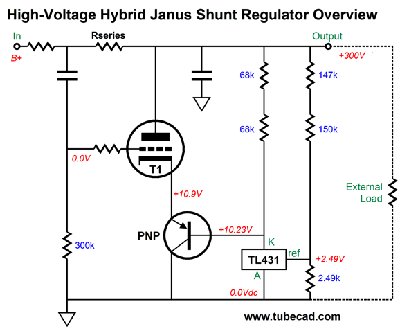 The solid-state portion is filled by the TL431 IC shunt-regulator/voltage reference. The PNP transistor effectively superchargers the TL431, as it can pass amperes of current. The way this shunt regulator works is that the TL431 strives to see a fixed 2.49Vdc at its reference pin. Should the regulator's output voltage grow too high, the LT431 will dramatically increase its current conduction, causing the PNP emitter voltage to fall, which in turn pulls down the triode's cathode voltage, causing the triode's current conduction to spike, which will force the output voltage back in line.


| www.tubecad.com Copyright © 1999-2021 GlassWare All Rights Reserved |