| John Broskie's Guide to Tube Circuit Analysis & Design |
05 January 2022 Post 551
Happy New Year
2022 and Beyond
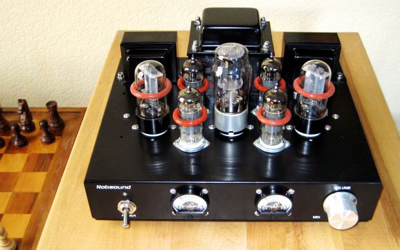
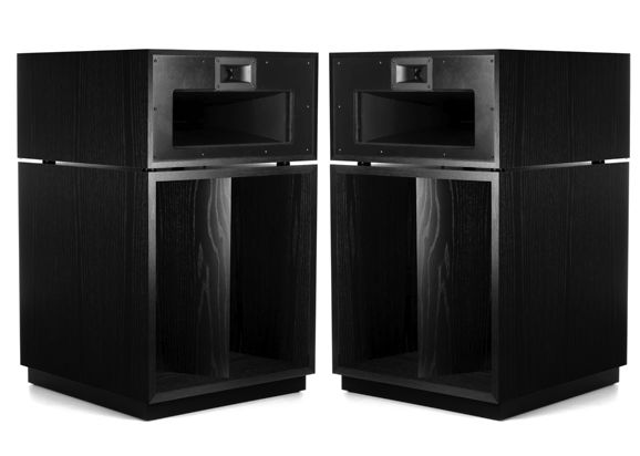
Cute Flea Power Amplifier (I used to own about four times more iron, but when we fled California 12 years ago, I had to part with bulk of it, sadly. The joke at the time was that the FAA bared flights over my house, as my iron collection threw off the airplane's instrumentation.)
I finally found my autoformer. Once the black cube step-up transformer was plugged in and the tiny amplifier attached, the tubes began to glow and lovely sounds poured from my loudspeakers. Amazing, simply amazing how good it sounded. Single-ended glory from two tiny output transformers that barely look large enough to power headphones. But then, flea-power amplifiers, with their natural sound, so easily beguile our jaded audiophile ears, as startling as finding a pearl in your oyster. It's amazing how good so few watts can sound. I have heard 3-watt wonders, filled with 2A3 or EL84 tubes, sing beautifully, seemingly far more powerfully than their tiny wattage would imply. Back in the 1990s, a friend started hoarding tiny output transformers from 1950s and 1960s radios, TVs, and stereo systems, claiming that they were responsible for a great sound that big output transformer could not deliver. At the time, I thought he was crazy; not today. As the great, wonderful, and lovely American philosopher put is so concisely:
The huge problem with flea-powered amplifiers is that they are like tasting a single delicious appetizer that sparks our appetite, but does not sate our hunger. With the exception of horn loudspeakers, few conventional loudspeakers can play loud enough with only a few watts of power. Some high-end speakers, such as those from Magnepan, need at least 50W just to start dancing. This situation made me think again of the topic of augmented loudspeakers, wherein an internal power amplifier helps the external power amplifier drive the speaker.
Diffraction Loss and Augmented Amplifiers
Many high-end loudspeakers, such as the flagship Vandersteen models, hold an internal power amplifier to drive the internal subwoofer; thus, freeing the external power amplifier from that onerous task. What if we were not so ambitious? For example, say we only wanted to augment the existing small woofer's output to overcome the low-frequency diffraction loss? Our goal would be flat bass, not deep and powerful bass.
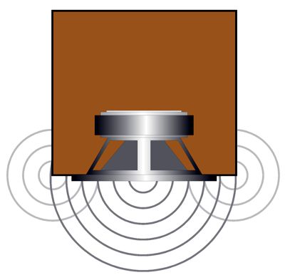
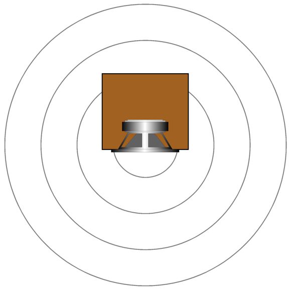
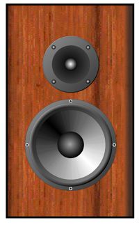
A small loudspeaker's sound radiation is not uniform. At extreme high frequencies, it radiates narrowly, like a flashlight beam; at low frequencies, omnidirectionally.
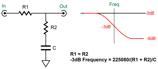
As the frequency rises, the enclosure width begins to form an obstacle to the sound wrapping around and the SPL rises as a consequence. By how much? In theory, by 6dB, since the loudspeaker went from omnidirectional to semispherical radiation. In practice, however, the amount can be as little as 3dB, but usually around 4dB. (In an anechoic chamber, we would measure a 6dB boost.) One workaround is to place a passive shelving network in front of the power amplifier, so the bass gets boosted. (Se post 541 for more information on this topic.)
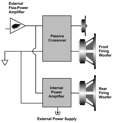
The downside to this workaround is that more amplifier power is required, which is the last thing we want to demand from a flea-power amplifier. For example, a +6dB boost requires twice the output voltage swing from the amplifier; twice the output voltage means four times more watts. Well, what if we add a secondary woofer, firing at the back of the enclosure, and an internal power amplifier? The extra woofer would only fill in the missing bass output, but we could let it run fullrange, i.e. until it ran into its own high-frequency limit. How much signal level should the rear woofer get? In an anechoic chamber, the same amount as the front woofer; in your living room, less. Just how much less depends on the speaker's location relative to the floor and walls.
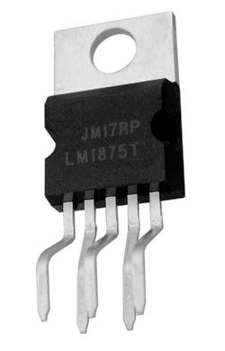
The best approach would be to include a volume potentiometer with a range of unity-gain to -6dB, so we could adjust the amount of compensation. With this setup, the internal power amplifier should be able to deliver up to the same amount of power as the front woofer sees. If the external power amplifier is a 4W flea-power amplifier, then the internal power amplifier need only put out 8Vpk into an 8-ohm load, as 8Vpk equals 4W with an 8-ohm woofer. The obvious solution would be to add a class-D amplifier, as they are small, run cool, and cheap. On the other hand, they often sound muddy and their high output wattage ratings are often into 2-ohm loads with 10% distortion. Of course, since they are so cheap, you could simply over-spec, say using a 200W unit when you only need 20W. Sometimes a simple solid-state class-B amplifier is better. As we only seek 8Vpk, a 24V external switching power supply and an internal LM1875 chip amplifier should do it.
The $5 LM1875 chip amplifier had lot of fans, back in the days prior to $20 class-D amplifiers, as the LM1875 made a fine little power amplifier with little effort or parts. Its big liability, however, is not its limited power output, about 30W, but its TO-220-5 case's high thermal resistance, which requires a large heatsink to keep the device from burning up. The workaround is to run the amplifier with a monopolar power supply, rather than a bipolar power supply. Why? The TO-5 tab is connected to the negative power supply pin, which in a monopolar power supply is ground. In other words, we can forgo the mica insulator and use a smaller heatsink. (In fact, the metal enclosure can serve as the heatsink in some applications.) An additional benefit to using the monopolar power supply is that the LM1875's output must be capacitor coupled, which makes the amplifier safe from an accidentally shorted output—not that this would be likely with an internal loudspeaker amplifier.
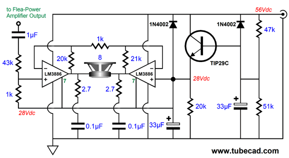
If the external power amplifier delivered up to 16W (16Vpk into 8 ohms), the power supply voltage would need to be increased to 48Vdc and a good-sized heatsink would be needed. Beyond 16W, the better choice would be the LM3886, which with a 56Vdc monopolar power supply can deliver up to 68W into a 4-ohm load and 38W with an 8-ohm load. What if even more power were needed to match the external power amplifier's output? We could use two LM3886 amplifiers in a bridge configuration.
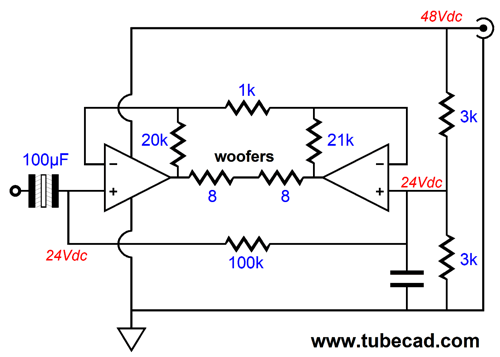
This configuration doubles the output voltage swing across the back-firing woofer, so we could expect twice the 68W output with a 56Vdc power supply, in other words, 136W. Note how no huge output coupling capacitor was used, but 2W 1k resistors were used to create a pseudo ground with the 56Vdc power supply. As far as each LM3886 is concerned, the load impedance is 4 ohms, not 8 ohms, which must be factored in when calculating the needed heatsink thermal resistance. Some quick calculations revealed that each LM3886 would need a heatsink with a thermal resistance below 0.4 °C/W, which will be large. If a single heatsink is used, then its thermal resistance must be below 0.2 °C/W.
On the other hand, if we used four LM3886 chip amplifiers, two in parallel on each side of the bridge topology, the heatsink could be much smaller, as we would have effectively halved the LM3886 case thermal resistance, along with the insulator washer and silicone thermal compound thermal resistance. In addition, we would get more potential output power, as each LM3886 would effectively see an 8-ohm load. How much? We simply quadruple the LM3886's wattage output into an 8-ohm load with +/-28Vdc power-supply rails, which is 38W, so 152W. Okay, let's return to the loudspeaker design. What if the second woofer is placed on the front? If nothing else, fullrange operation is out, as the second woofer's output will undergo the same diffraction loss as the first woofer; moreover, the second woofer's output will step on the first woofer's output, introducing lobbing effects, due to the frequency overlap and when distance apart is greater than a quarter of a wavelength of frequency reproduced. What is needed is low-pass 1st-order filter and reduced output for the second woofer, as the woofer need only augment the primary woofer's output up to the frequency that begins to sag.
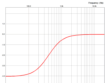
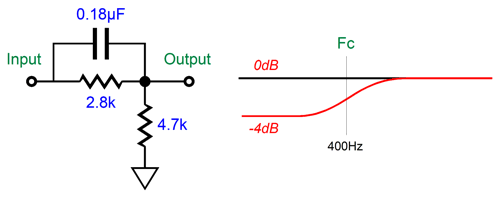
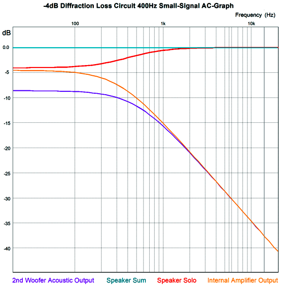
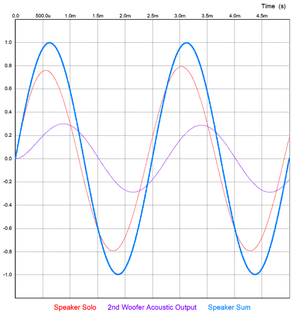
I created in SPICE a simple shelving network that centered at 400Hz and drooped by -4dB, which might match a small mini-monitor loudspeaker on tall speaker stands several feet from the back wall. I then added a parallel low-pass filter with a 310Hz transition frequency and a gain of -4.6dB that also passed through a similar shelving network, which effectively raised the transition frequency to 510Hz and lowered its "acoustic" output by an additional -4dB. Combing the two outputs resulted in a flat frequency response.
The following graph show the driver outputs at 400Hz.
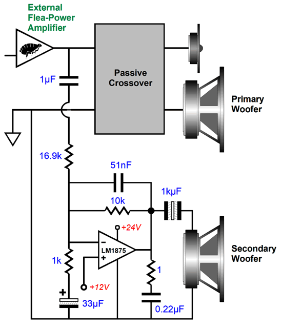
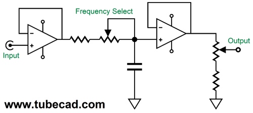
In theory, the concept is sound, but how do we translate it into reality? Here is one possible way to do it:
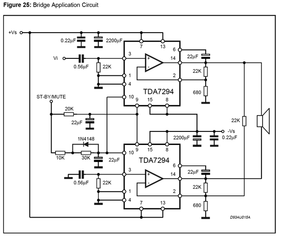
The +12V tap can be made from a two-resistor divider with equal value resistors across the 24Vdc B+ voltage from the external power supply. The 16.9k and 10k resistors set the required attenuation. Yes, with an inverting negative feedback setup, we can get gain or unity gain or attenuation, which is a nice feature. The 1k will baffle many. Its job is to allow us to use a non-unity-gain-stable amplifier in spite of the attenuation. The 1k resistor sets a non-inverting gain to 11, but it also throws away much of the negative feedback. Here is an example of the technique being used in a bridge amplifier that holds two TDA7294 chip amplifiers, which are not unity-gain-stable.
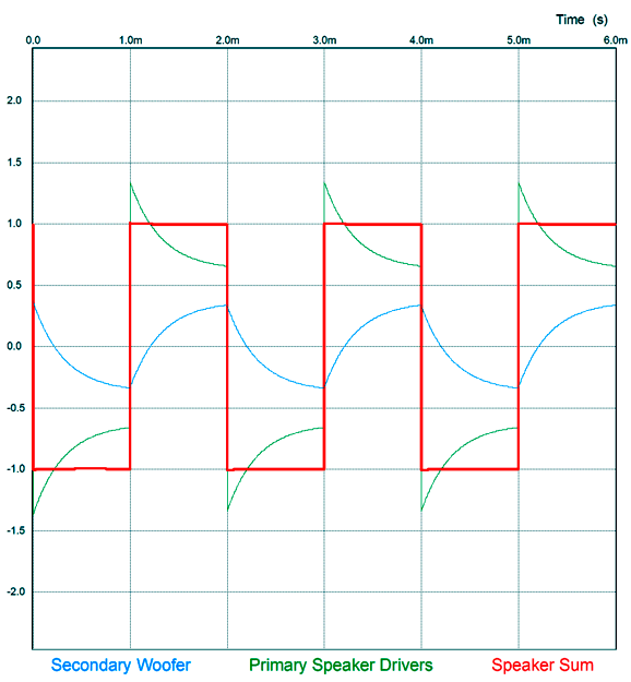
The top amplifier is configured as a non-inverting with a gain of 33.3, while the bottom amplifier is inverting with a gain of -1. Note at the bottom the two 22k resistors setting the bottom amplifier's gain to -1, but the added 680 implies a non-inverting gain equal to the top amplifier's. Also note how the bottom amplifier's non-inverting input is AC grounded through the 0.56µF capacitor, while the top amplifier uses a similar capacitor to accept its input signal. The important test is square waves, as they require more than just a flat frequency response, but a flat phase response. In SPICE simulations, square waves went in, square waves came out. This constitutes a theoretical proof of concept, but the real test must be made in reality with real loudspeaker drivers.
Of course, real speakers could never deliver such lovely square waves, as the the speaker drivers would have to exhibit infinite bandwidth and absolutely flat phase. The most important finding was that the secondary woofer's input signal was -4.6dB down relative to the primary woofer's. Why? It means that, in this example, the internal power amplifier need only put out 59% of the voltage swing that the external power amplifier delivers. In the example of the flea-power amplifier putting out 8Vpk (4W into 8-ohms), the internal amplifier would only have to deliver 4.71Vpk of output voltage swing. Of course, if the diffraction loss conformed to the textbook -6dB, the secondary woofer's output would have to match the primary woofer's, so the internal power amplifier's output would have to match the external power amplifier's output. Conversely, if the droop only amounted -2dB, the secondary woofer and internal power amplifier would loaf along, as so little would be demanded from them.
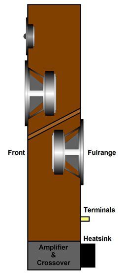
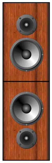
A simple test setup might be to take two existing mini-monitor loudspeakers and arranged thus:
The top speaker is the primary one and the bottom is the test secondary woofer (we ignore its internal crossover and tweeter in this test). We feed the bottom speaker from a separate amplifier whose signal passes through variable low-pass filter and an attenuator.
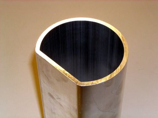
The first step would be to feed only the top speaker a 1kHz sinewave, and then we mark the SPL. Next, we set the variable filter frequency to its highest setting. We then feed both amplifiers a low frequency sinewave, say 100Hz, and adjust the volume level to the bottom amplifier until SPL meter reads the same SPL that the top loudspeaker produces with a 1kHz signal. The next step would be to adjust the variable filter frequency until we get the flattest bass response. We mark this frequency and amount of attenuation. Finally, we set about designing a low-pass filter and attenuator circuit to feed the bottom amplifier. Once we have this, we can design a new speaker enclosure that would hold two woofers and an internal power amplifier. Actually, I would place the internal power amplifier inside the speaker stand and make the stand an integral part of the loudspeaker. The metal stand could also serve as the internal power amplifier's heatsink. For example, 4-inch diameter copper pipe cost about $7 a foot and aluminum pipe would be cheaper still.
In addition, they sell aluminum half-round and D-shaped plenum extrusion tubing. The D-shape extrusion would be excellent, as we could attach the amplifier to the flat side in the back, while the front presented the cylindrical aspect. Powder-coated in a semi-gloss black, the stand would prove attractive and a better heat dissipater than the plain metal finish.
Augmenting Woofers
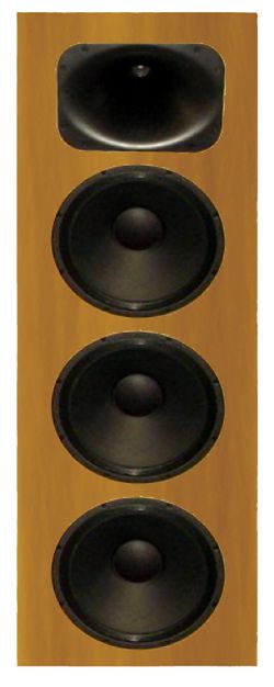
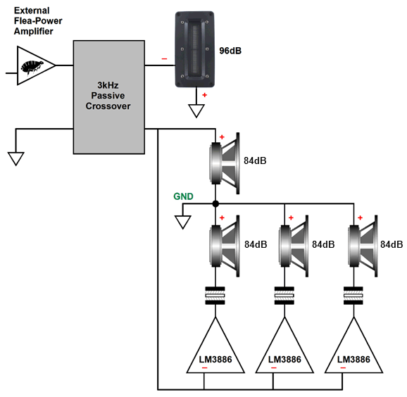
The downside to the cheaper alternative is that the woofer's SPL falls far short of the midrange and tweeter, so these last two drivers must be padded to lower their output to match the woofers, say 96dB. To bring the woofer SPL up to 105dB would require 9dB more SPL. Interestingly enough, three woofers wired in parallel yield a 9.54dB increase due to the threefold increase in radiating surface area.
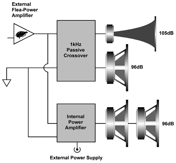
Of course, we never get anything for free in physics, as three 8-ohm woofers in parallel create a 2.66-ohm load, so the power amplifier would have to deliver three times more wattage. With a flea-power amplifier, this is nonstarter. What if we let the flea-power amplifier drive just one woofer, while an internal power drove the other two woofers? The flea-power amplifier would still see an 8-ohm load, while the internal amplifier would see a 4-ohm load. The result would 105dB efficiency with no padding of the midrange and tweeter. The internal power amplifier would have to deliver the same voltage swing as the flea-power amplifier, but twice the current swing; thus, twice the power. In other words, a 4W flea-power amplifier would need augmentation with an 8W amplifier.
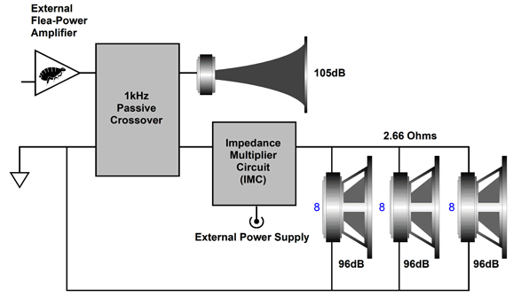
An alternative approach would be to place all three woofers in parallel and add an impedance-multiplier circuit (IMC) to make the 2.66-ohm load appear as an 8-ohm load to the flea-power amplifier.
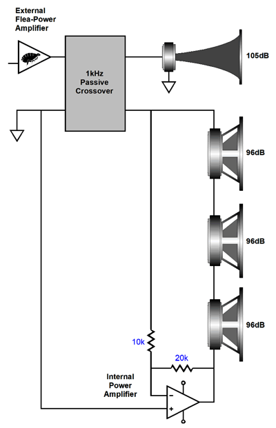
The IMC delivers twice the current that the flea-power amplifier develops. The only problem is making an IMC, as it requires a unity-gain-stable power amplifier. Some of the Burr-Brown chip amplifiers are unity-gain stable, as is the old National Semi LM12; sadly, it is out of production, although they can be bought at eBay for about $50 each. The Burr-Brown (Texas Instruments) OPA549 is unity-gain stable, but costs about three times more than the LM3886 and is hard to source. Another possible approach would be to place the three woofers in series, making a 24-ohm load. The flea-power amplifier drives one end of the woofer string, while the internal power amplifier drives the other end in anti-phase and with twice the voltage swing.
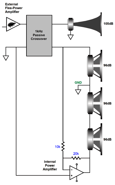
As far as the flea-power amplifier is concerned, the load it sees is 8-ohms; as far as the internal power amplifier is concerned, a 16-ohm load. Since all three woofers see the same current flow and voltage swing, we get our 9.5dB boost in SPL. The internal power amplifier must deliver twice the power and voltage swing of the flea-power amplifier. Of course, some may balk at the idea of the flea-power amplifier's delicate output being placed in series effectively with a cheesy solid-state chip power amplifier, thereby possibly sullying the sonic glory. The solid-state chip power amplifier applies a gain of two upon the flea-power amplifier's output, however, so it should mimic its signal closely, including its harmonic distortion structure. In other words, a strong 2nd harmonic will still come out strong from the solid-state chip power amplifier. Well, an alternative arrangement would simply break the series connection by grounding the first woofer.
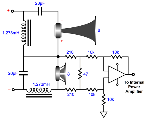
In fact, this arrangement allows us to use a fancier passive crossover, say series Linkwitz-Riley, where the woofer is not terminated into ground.
Note that the woofer makes no direct connection to ground.
The OpAmp-based differential amplifier along with the 210-ohm resistors and the 47-ohm resistor monitor the voltage across the woofer, in spite of what each terminal sees relative to ground; they also reduce that voltage by tenfold at the OpAmp's output. Why? The solid-state chip power amplifier, say an LM3886 powered by a 48Vdc external switcher power supply, will provide a gain of 1:20 (26dB), so its output will be twice that of the flea-power amplifier; effectively, its gain becomes 1:2, so all the woofers see the same signal, both in magnitude and frequency content. Since the differential amplifier's OpAmp runs off the 48V power-supply rail, we must use a high-voltage OpAmp. The first that comes to mind is the OPA445, but I believe that a LTC2057HV would prove a better choice. Why? It is slow, with a slewrate of only 0.45V/μs, whereas the OPA445 slews 15V/μs. In this application, high speed is not needed and it can lead to instability problems. In addition, the LTC2057HV is less than half the cost. One nice feature of this arrangement is that LM3886 just loafs with the 16-ohm load. Indeed, we can get away with a far smaller heatsink as a result, as so little power is dissipated by the heatsink. How little? About 9W, worst case, when the LM3886's idle current is 85mA and the maximum output power is 12.5W (20Vpk). What if the flea-power amplifier's output is a more robust 16W, which mean 16Vpk of peak output voltage swing? Well, the 48Vdc power supply will no longer prove sufficient with a single LM3886. On the other hand, two LM3886s in a bridge-amplifier configuration would work, but a much larger heatsink would be needed, as the maximum heatsink dissipation increases to 30W.
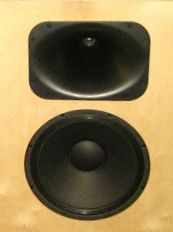
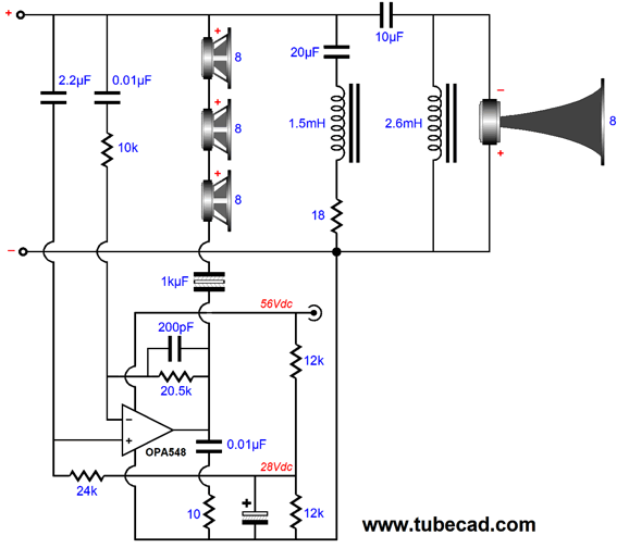
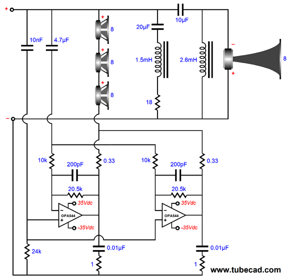
What if the flea-power amplifier puts out 36W (24Vpk), well then it is not a flea-power amplifier. If this loudspeaker must work with the higher output wattage, then we must switch to a powerful class-D amplifier and wire the woofers in parallel, making a 4-ohm load. A 200W class-D amplifier would work with an external power amplifier up to 100W. Returning to the flea-power amplifier, what if we knew that we would never use a more powerful amplifier, as we knew we could never find as sweet-sounding power amplifier? In this case, the following design would make a lot of sense. We start with a high-frequency horn, such as those made by the Italian loudspeaker driver manufacturer, Faital Pro, which cover the range of 1kHz to 20kHz. Next we use three 96dB 10-inch woofers, such as the Faital Pro 10FE200. So far, it sound a lot like the first example, but where it will differ is that no crossover inductor will be used. The three woofers are wired in series, making a 24-ohms load. The flea-power amplifier connects to the top of the woofer string, while an OP548 chip amplifier from Burr-Brown (TI) connects to the bottom of the woofer string. The OPA548 is unity-gain stable so we are able to pull off the following setup.
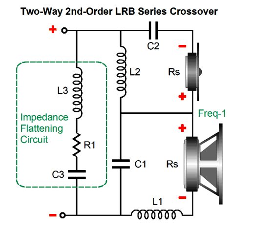
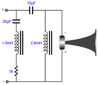
From DC to about 663Hz, the OPA548 amplifies by two and inverts the flea-power amplifier's output voltage, giving each woofer the same voltage drop that the flea-power amplifier puts out. Thus, the flea-power amplifier effectively sees an 8-ohm load, while the OPA548 sees a 16-ohm load. At the transition frequency of 663Hz, the OPA548 ceases to function as an inverting amplifier and becomes a unity-gain power buffer. The result is that the woofer string sees the same signal in phase at high-frequencies, which means no sound output, as the woofer are intrinsically differential device; no voltage differential, no sound. Effectively we have replaced the crossover inductor with this clever circuit. As far as the flea-power amplifier is concerned, it is driving an 8-ohm load in series with a 1.92mH inductor, as the load resistance is 8-ohms at DC and remains flat until impedance begins climbing with higher frequencies. So we save the cost of the inductor, was that a big deal. Oh my God, yes! Forget about the cost; think about the signal not having to travel through a hundred feet of magnet wire and deal with inductor core nonlinearities and saturation. You have bought $2,000 loudspeaker cables because you are on a budget, otherwise you would have bought $20,000 cables, since you know cable makes the system. Let's say you are not counting your pennies, so you own $20,000 cables, what happens when the delicate signal must travel through a jungle of passive crossover parts? Trust me, the wire in the inductor didn't cost $20,000. Your power amplifier boasts a dampening factor of 1,000, but the inductor's DCR comes in at 0.8 ohms, dramatically reducing the dampening factor. Over forty years ago, I spoke to a loudspeaker designer. I asked how they had achieved such midrange clarity from an 8-inch woofer and dome tweeter. His answer was that no woofer inductor was used; instead, they designed the woofer to roll-off smoothly at high frequencies and crossed over the tweeter to match the woofer rolloff. He explained how woofer inductors just muddied the sound. Well, if you have ever tried bi-amping or tri-amping, you have no doubt heard the improved performance from the woofer—actually from all the drivers. Okay, let's add the rest of the components, starting with the high-frequency driver and its passive crossover.
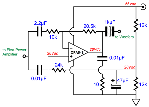
The high-frequency driver gets a Linkwitz-Riley 2nd-order high-pass crossover set to 1kHz. Note the phase reversal on the driver. The 20µF capacitor, 1.5mH inductor, and 18-ohm resistor are an impedance-flattening network. The next step is to include the OPA548 and the external 56Vdc power supply.
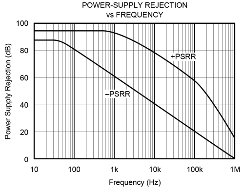
The two 12k resistors form a two-resistor voltage divider that creates a reference voltage to center the OPA548's output at 28Vdc. The 100µF capacitor simply offers a low-impedance path to ground. The 10k and 20.5k resistors set the OPA548's gain to slightly over 1:2. The 200pF capacitor simply limits the OPA548 bandwidth to 39kHz. The 2.2µF capacitor blocks the 28Vdc from the ground potential and imposes a 7Hz cutoff. The 1kµF output coupling capacitor allows bandwidth down to 10Hz. (If we used a 68µF capacitor instead, the low-frequency cutoff frequency would be 100Hz.) The 10-ohm resistor and 0.01µF are there to ensure stability at high-frequencies. Since the OPA548's mounting tab is connected to its negative power-supply pin, which is ground in this setup with the monopolar power supply, no isolating mica or silicone washer is needed between the tab and the heatsink, although a little thermal grease should be used. An added advantage to using a monopolar power supply is that OPA548, like most OpAmps, offers far better PSRR at its positive power-supply pin than at its negative power-supply Pin. By grounding the negative power-supply pin, we realize only the better PSRR.
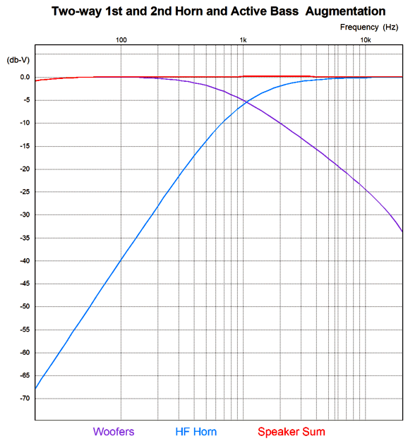
How well does this asymmetrical crossover work? Far better than I expected. Here is the SPICE-generated graph.
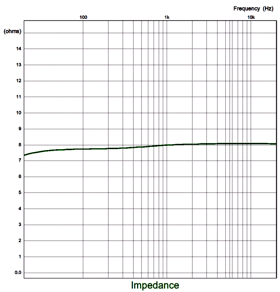
A tiny bit lumpy, but when we consider how massively lumpy actual loudspeaker frequency response plotlines are, it not bad at all. Note how the woofer rolls off at a f1st-order slope, while the high-frequency driver rolls off at a 2nd-order slope. The impedance plot was also satisfying. (Without the impedance-flattening network, the impedance peaks at 14 ohms.)
This graph assumes resistor-flat speaker driver impedances. In other words, what is missing two Zobel networks, one for each driver. Do not forget that this design assumes a 4W flea-power amplifier. The OPA548 clips above 11Vpk of output voltage swing from the flea-power amplifier; 11Vpk equal 7.5W into 8 ohms. If a 10W single-ended power amplifier were used, we can expect some clipping. Interesting enough, we may NOT hear it. What? Only the woofers would see the clipped signal, not the horn driver. Woofers are high-frequency limited, so they cannot pass the sharp edges of a clipped signal the way a tweeter can. In other words, the ear would still hear clear highs. The OPA544 can, in contrast, run off a 70Vdc monopolar power supply. If we were willing to forgo the ease and low cost of an external switcher power supply, we could build a conventional 70V power supply in the loudspeaker enclosure. With the higher B+ voltage, I would use two OPA544 amplifiers in parallel, as they are only rated for 2A of output; in addition, the heatsink becomes less of an issue.
Note that both amplifiers share the same 4.7µF capacitor and input signal, but each gets its own 470µF output coupling capacitor. This arrangement should allow flea-power amplifier up to 16W of power output. As far as each OPA544 is concerned, the load impedance is 32 ohms.
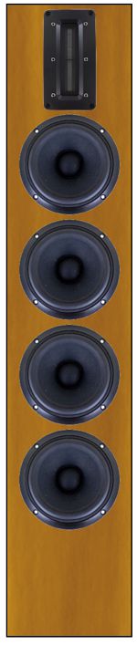
Smaller Design Example
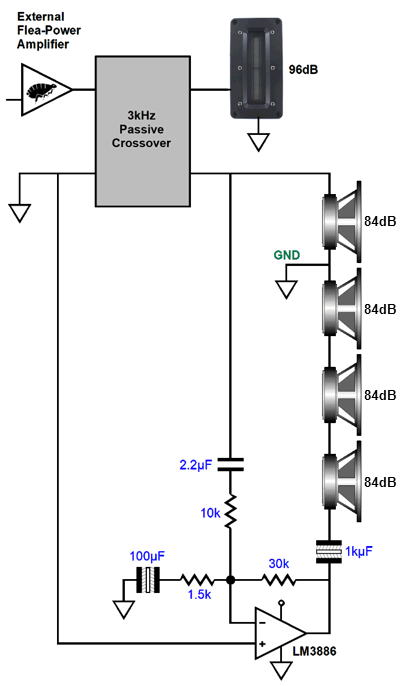
Instead of the horn-loaded high-frequency driver, we could use a tweeter with a relatively high SPL, say 96dB (for example, the Aurum Cantus G2 ribbon or Fountek NeoCd2.0M-blk), with as many 84dB, 5-inch woofers as are needed to match the tweeter's output. In this example, four 84dB 5-inch woofers wired in parallel with 2.83Vavg at 1 meter would produce 96dB due to the fourfold increase in radiating surface area, 20 x log(4) = +12dB. Imagine a 36-inch tall speaker with a small footprint of 8 by 8 inches. Of course, four 8-ohm woofers in parallel present a 2-ohm load, which our flea-power amplifier will not like. So, much like the previous example, we let the flea-power amplifier only drive only one woofer, while the internal power amplifier drives the other three woofers.
Since 4W into 8-ohms equals 8Vpk of voltage swing, the three woofers in series must see at least 24Vpk, which implies a 36W power amplifier driving 8-ohm loads. But when driving a 24-ohm load, the 24Vpk only represents 12W of power output. We might be able to pull this off with a single LM3886 powered from an external 56Vdc switcher desktop power supply. The LM3886 would only dissipate 9W or so at full power into the 24-ohm load, so not much of a heatsink would be needed. The only problem with this arrangement is that assumes a 4W flea-power amplifier is the limit. What if we use 40W tube-based power amplifier instead? Well, 40W into 8-ohm equals 25.3Vpk, which means that the internal power amplifier would have to swing three times as much voltage, i.e. 75.9Vpk. A no go situation, alas. One workaround would be to give each of the three woofers its own LM3886 power amplifier.
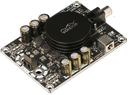
When driven by the flea-power amplifier, each LM3886 will loaf along, delivering only 4W of power and producing only 8Vpk of voltage swing. But when driven by a more powerful external amplifier, each LM3886 will deliver the needed augmentation. A large heatsink, however, is needed in this arrangement. An alternative arrangement would be to place the three woofers in parallel, thereby making a 2.66-ohm load. In this configuration, 8Vpk also equals 12W with the 2.66-ohm load. The best amplifier choice in this setup would have to be a class-D amplifier, as many are designed to work into 2-ohm loads (think car stereo applications). For example, the Sure/Wondom AA-AB31184 mono power amplifier that delivers 100W into 2-ohm loudspeakers and runs off a 24Vdc monopolar power supply. Its fixed gain is 26dB or 1:20, so we must place a two-resistor voltage divider at its input that will reduce the signal across the primary woofer by 1/20. This class-D amplifier is available at Parts-Exress.com for less than $50.
To get 100W into a 2-ohm load requires 20Vpk and 10Apk. With a 2.66-ohm load, however, we can expect only 75W, which means that the flea-power amplifier should not exceed 25W of output power, as 75W/3 equals 25W. Still, with two 96dB loudspeakers in a bedroom, 25W would hurt your ears.
Music Recommendation: Toru Takemitsu
I had only the vaguest awareness of Takemitsu, having seen him referred to as a movie score composer. Well, his music grabbed me enough to search for more.
Yoshirō Vladimir Irino was a Japanese composer born in the Soviet Union in 1921; he died in 1980 in Japan. The first track on this short album is a conversation with Irino in Japanese, which sadly I do not speak. His Sinfonietta was definitely worth the listen. Then the filth track is a dialogue with Takemitsu. The last track was his Requiem for string orchestra.
The above album is entirely devoted to Takemitsu and it includes many of his most famous pieces, such as A Flock Descends into the Pentagonal Garden. //JRB
Very few can imagine just how much hard work is required to make one of my posts. If you have any sort of inkling or intuition of what is involved, please think about supporting me at Patreon.
User Guides for GlassWare Software
For those of you who still have old computers running Windows XP (32-bit) or any other Windows 32-bit OS, I have setup the download availability of my old old standards: Tube CAD, SE Amp CAD, and Audio Gadgets. The downloads are at the GlassWare-Yahoo store and the price is only $9.95 for each program. http://glass-ware.stores.yahoo.net/adsoffromgla.html So many have asked that I had to do it. WARNING: THESE THREE PROGRAMS WILL NOT RUN UNDER VISTA 64-Bit or WINDOWS 7 & 8 & 10 or any other 64-bit OS. I do plan on remaking all of these programs into 64-bit versions, but it will be a huge ordeal, as programming requires vast chunks of noise-free time, something very rare with children running about. Ideally, I would love to come out with versions that run on iPads and Android-OS tablets.
//JRB |
|
I know that some readers wish to avoid Patreon, so here is a PayPal button instead. Thanks. John Broskie
John Gives
Special Thanks to the Special 85 To all my patrons, all 85 of them, thank you all again. I want to especially thank
I am truly stunned and appreciative of their support. In addition I want to thank the following patrons:
All of your support makes a big difference. I would love to arrive at the point where creating my posts was my top priority of the day, not something that I have to steal time from other obligations to do. The more support I get, the higher up these posts move up in deserving attention.
Only $12.95 TCJ My-Stock DB
Version 2 Improvements *User definable Download for www.glass-ware.com |
||


| www.tubecad.com Copyright © 1999-2022 GlassWare All Rights Reserved |