| John Broskie's Guide to Tube Circuit Analysis & Design |
23 March 2022 Post Number 555 Special Thanks to
50Hz to 500Hz RIAA EQ Using Negative Feedback
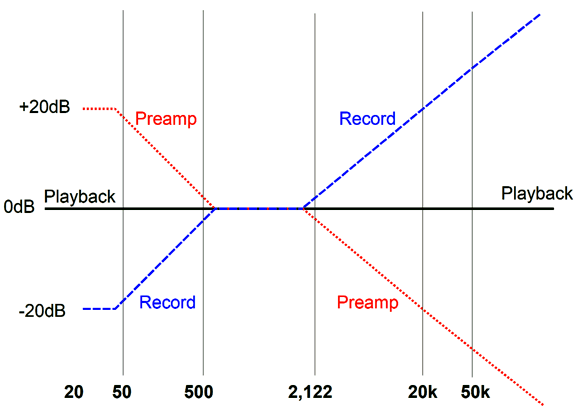
Of course, when dealing with LPs, we must also deal with their playback and the required phono preamp. As I looked through some of my posts on this topic, I realized that I haven't covered an old and interesting tube-based way to implement half of the required equalization curve. Let's start at the beginning. An LP's signal is not pressed with a flat frequency response, nor is the signal leaving the phono cartridge flat. Instead, the signal is weak in the bass and strong in the highs, as it conforms to the RIAA equalization curve that place transition frequencies at 50Hz, 500Hz, and 2122Hz. The phono preamp must then impose an inverse of the LP equalization to produce a flat frequency output; this requires boosting the bass between 50Hz to 500Hz and cutting the highs above 2122Hz.
The inverse equalization can take many forms, such as active equalization through negative feedback or passive equalization through passive networks or some combination of active and passive. I happen to like active equalization between 50Hz to 500Hz and passive above 2122Hz. Why? Negative feedback is famous for producing tighter bass, but not smoother highs. If we look at an OpAmp's open-loop gain, we see a plotline like the following.
Note the insane amount of gain at DC. In this example from the OPA1612's data-sheet, we see a DC gain of about 110dB (or 1 : 316,000). We also see a 1st-order low-pass falloff in gain at a rate of 6dB per octave and 20dB per decade. Thus, at 10kHz, gain is down by 30dB from its DC level with almost 80dB of gain, there is still plenty). Well, the bottom half of the RIAA equalization curve, the frequencies from 50Hz to 500Hz, fit nicely in the OpAmp's open-loop gain. This means that from DC to 500Hz, the OpAmp will deliver an equal margin of negative feedback. Frequencies above 500Hz, however, see a decreasing amount of negative feedback due to high-frequency gain loss.
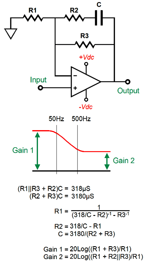
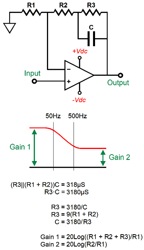
Actively imposing the bottom half of the RIAA equalization curve with OpAmps is easy enough, as it only requires three resistors and one capacitor in the negative feedback loop.
This design example is from post 497, which includes the following variation.
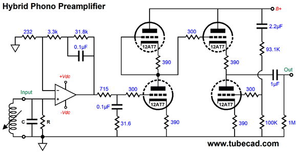
If you are interested in making a hybrid phono stage that uses an input OpAmp gain stage followed by a tube-based gain stage, be sure to check out post 497, as you will see circuits like the following.
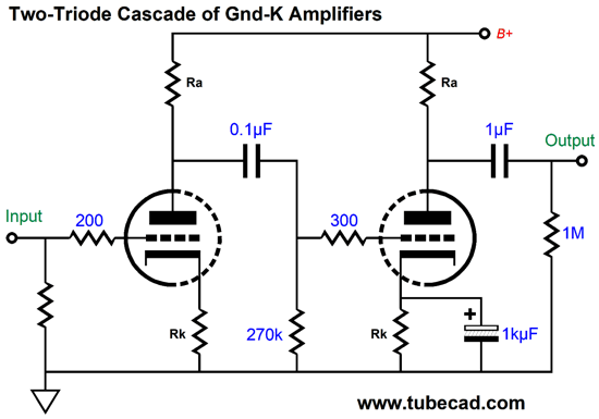
This hybrid phono preamp produces a gain of about 52dB. If less gain is needed, we could simply swap out the 12AT7 with a 12AY7 or 12AU7. If more gain is needed, we would swap in a 5751 or 12AX7. From the 12AU7 to the 12AX7 is a 16dB spread. Alternatively, we could alter the OpAmp's negative feedback resistor values to either increase or decrease the gain. Let's now move on to pure-tube-based circuits. We start with a simple two grounded-cathode amplifiers in cascade.
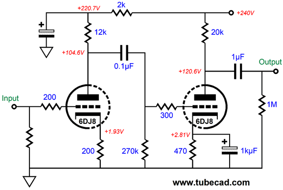
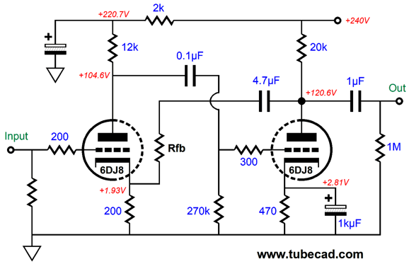
The frequency response is flat, save for the high-pass rolloffs due to the coupling capacitors. The next step is to measure the gain. Here is a possible design example that uses a 6DJ8.
In SPICE simulations, the gain came in at 52.5dB. The next step is to add a negative feedback loop.
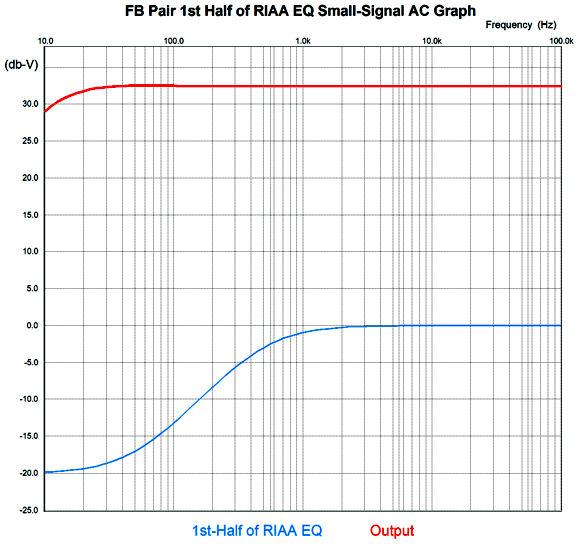
Our goal is to determine what resistor value for Rfb yields a closed-loop gain of 32.5dB. In SPICE simulations, the 1% resistor value of 9.76k worked best. Now, we must replace the 4.7µF capacitor with a value that yields the desired bottom half of the RIAA equalization curve. We take the RIAA equalization time constant of 3180µs and divide 3180 by (200 + 9760) and get 0.03188µF as the answer. We round this capacitor value up to 32nF and see how it works in SPICE simulations.
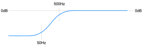
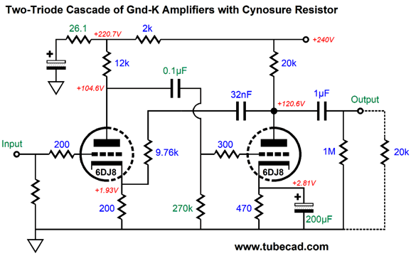
The input signal (blue plot) displays the bottom half of the RIAA equalization curve, with 5Hz being -20dB down relative to 5kHz. The tube circuit's output is nicely flat. By the way, the 1µF output coupling capacitor and 20k volume potentiometer resistance are part of the equalization. In other words, if a 100k potentiometer is used instead, we must use a 0.2µF output coupling capacitor value, as the 1µF coupling capacitor would produce a 0.8dB bump at 26Hz. Since we desire the highest PSRR in a phono preamp, let's add my signature "cynosure" Aikido mojo resistor and optimize the other part values for the best PSRR.
The 26.1-ohm cynosure resistor leaks a tiny portion of the ripple into the signal leaving the first stage, which the second stage then amplifies and inverts, which produces a deep null in the hum frequencies.
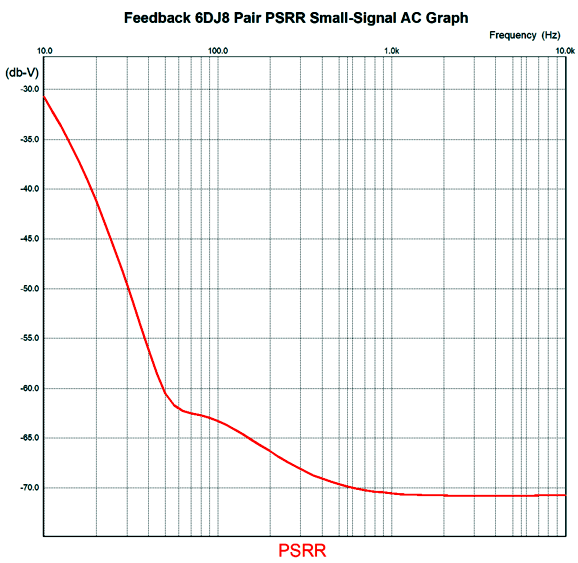
With the cynosure resistor in place, The PSRR at 100Hz improves by 40dB, which is huge. Note that the second grounded-cathode amplifier's cathode resistor is now bypassed by a 200µF capacitor, not the original 1kµF capacitor. Sometimes less is, indeed, better. Unfortunately, the nice round 200 figure will seduce many into believing that the value is relatively arbitrary; it isn't. Okay, let's now try a different tube, a 6SN7.
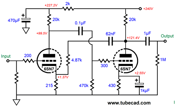
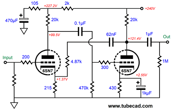
Since a 6SN7 triode only offers 60% of the amplification factor (mu) of the 6DJ8, we can expect much less gain. How much less? A quick guess would be 0.6² or 0.36 as much gain; put in dBs, the expected open-loop gain will be about 8.9dB lower. SPICE simulations somewhat confirmed that math, as the closed-loop gain came in at 24.9dB. The expectation was 23.6dB. In other words, we got a tiny bit more gain. Why the discrepancy? I used the tube manual's mu of 20 for the 6SN7 and 33 for the 6DJ8. If we use a slightly lower mu for the 6DJ8 or a slightly high mu for the 6SN7 we would hit the target gain difference. As a first approximation, it's not that bad. To recap, we first find the two grounded-cathode amplifier cascade's gain, then we seek a negative feedback loop resistor value that will reduce the gain to a tenth, and last we find the terminating capacitor value that will impose a 50Hz-to-500Hz shelving curve on the output signal, which will undo the bottom half of RIAA equalization curve imposed on the LP. We can add extra fanciness, say a regulated power supply or a cynosure resistor.
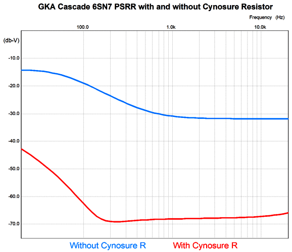
This added resistor improves the PSRR substantially.
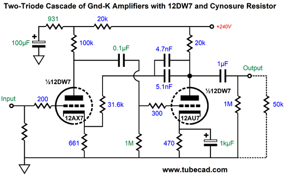
A better than 40dB improvement at 100Hz is well worth the cost of the added resistor ($0.10). In contrast, the typical audiophile practice of throwing his wallet at the problem, i.e. adding extra $$$ capacitors and inductors, sometimes achieves similar results, but usually introduces new problems. For example, unshielded or mis-aligned inductors can inject hum into a circuit. One last design example, here is a 12DW7/ECC832/7247 based version.
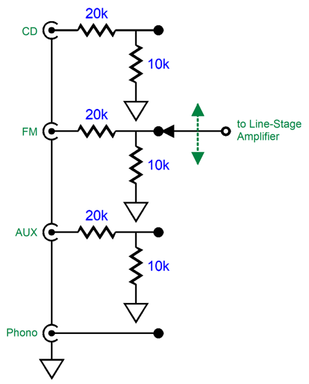
Note the 50k volume potentiometer and the 1M grid resistor. The gain came in at 32.6dB in SPICE simulations, which might be enough with high-output cartridges or with a high-gain linestage amplifier. Making a high-gain tube-based line-stage amplifier is a breeze. By high-gain I mean a gain over 12dB (1:4), say between 20dB and 30dB. Thus, the high-gain tube-based line-stage amplifier would make up for the missing phono preamp gain. The problem, of course, is that the other signal inputs will play too loud. Here is the simple workaround.
We pad all the input RCA jacks, save for the phono RCA jacks. The phono preamp effectively gets a 9.5dB boost relative to the other signal sources, such as an FM tuner or DAC.
Complete Phono Preamps with Active and Passive Equalization
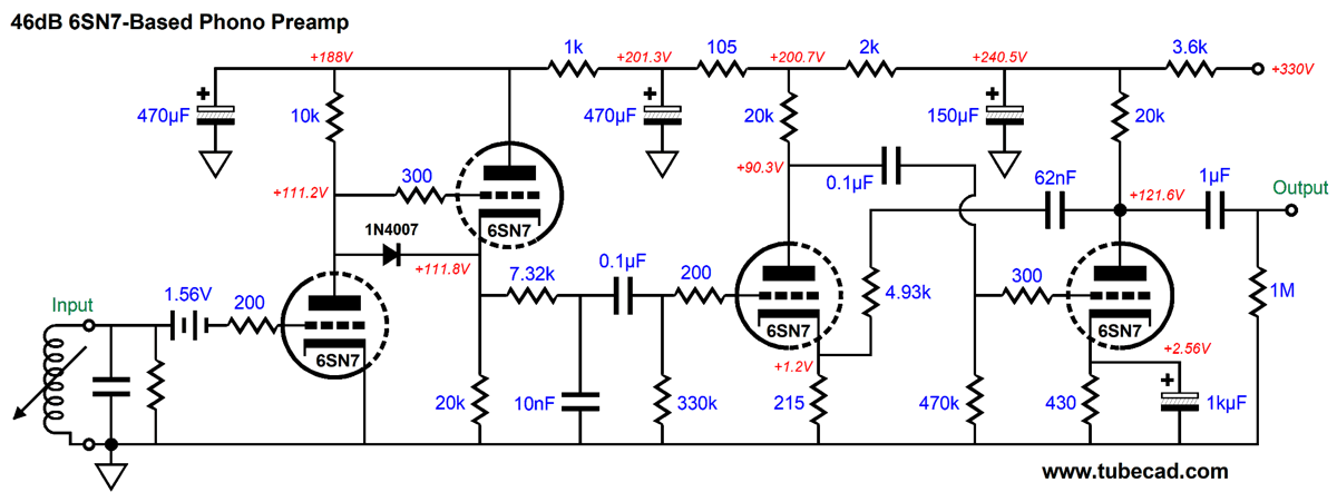
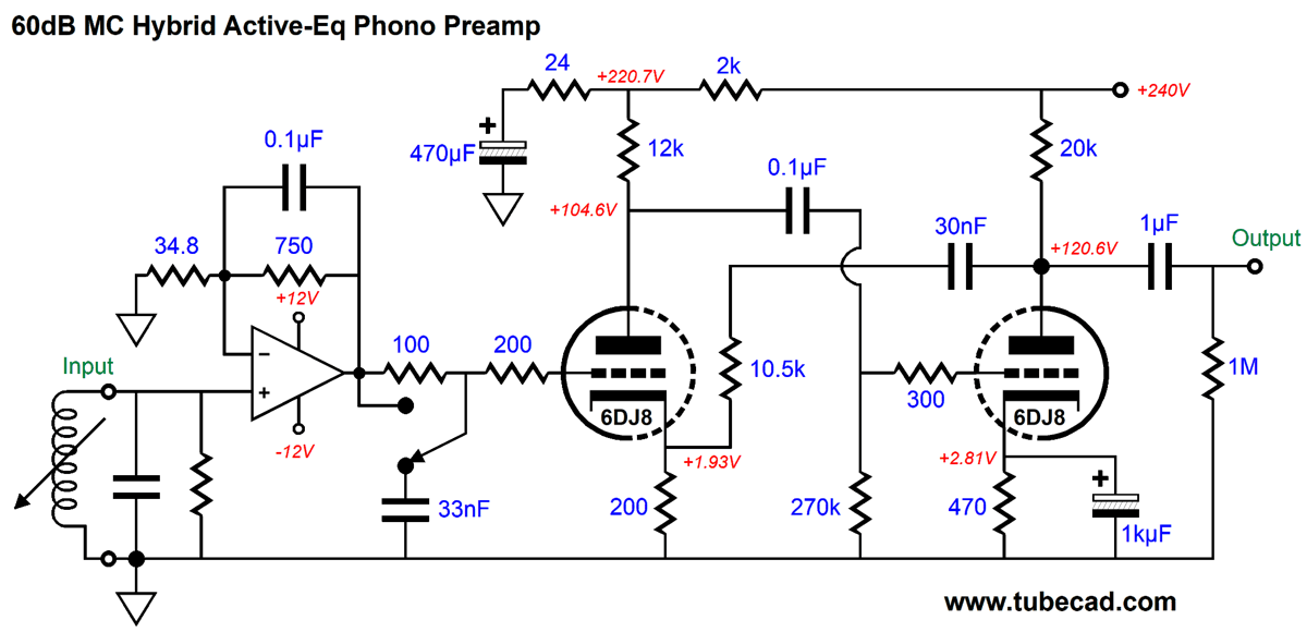
The input grounded-cathode amplifier forgoes cathode bias through a cathode resistor, relying instead on fixed bias from a AA battery. (The battery can be bypassed with a high-quality film or PIO capacitor.) The second stage uses a cathode follower to produce a low output impedance, which drives the low-pass RC filter made up of the 7.32k resistor and 10nF capacitor. The cathode follower's output impedance must be included in the filter's calculations, as must be the 330k grid resistor's resistance. The combined impedance equals 7.5k, which against the 0.01µF capacitor gives us a time constant of 75µs and a transition frequency of 2122Hz. The 1N4007 diode protects the cathode follower's triode at turn-on, when the cathode is cold and not conducting, but the B+ is fully realized. The final gain is 46dB and the batteries (one per channel) must be changed every five years or so. This is an all-tube effort that would appeal to many LP lovers. But for those with low-output moving-coil cartridges, more gain is needed. Although we could throw more tubes at the circuit, the lower-noise alternative is to make a hybrid phono preamp that uses a low-noise OpAmp as the input stage.
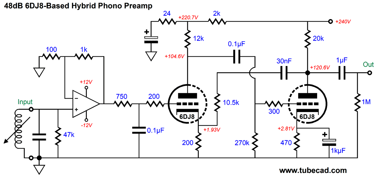
The OpAmp delivers a gain of 27dB and implements the second half of the RIAA equalization through the 0.1µF capacitor shunting the 750-ohm negative-feedback resistor, causing a shelving of frequencies above 2122Hz that then flattens at about 48kHz. Some argue that since the cutting head used in making the LP master offers only limited bandwidth, we should not slavishly abide by the RIAA equalization curve, as a gently rising high-frequency response works to undo the limitations of the LP pressing process. Others argue that the LP's playback presents ticks and pops that are high-frequency rich and can only cause problem further down the audio stream of equipment. Well, the inclusion of the switch and the 33nF capacitor allows a user to choose his preference, as in the down position, the 100-ohm resistor and 33nF capacitor create a low-pass filter at 48kHz. Note how the OpAmp is DC coupled to the 6DJ8's grid and that only two coupling capacitors were needed. The OpAmp runs off a +/-12V bipolar power supply, but could be powered by two 9V batteries instead. (Rechargeable "9V" batteries deliver either 7.2V or 8.4V of voltage, which would also work to power the OpAmp.) Here is an alternative lower-gain version wherein the 2122Hz transition is handled by an RC filter.
The OpAmp runs a flat output and its gain can readily be changed without throwing off the RIAA equalization, which allows a great deal of flexibility, as we could add a DIP-switch array of possible gains from the OpAmp. As configured in this schematic, the OpAmp's gain is 1:11 or 20.8dB. The 750-ohm resistor and 0.1µF capacitor define a 2122Hz low-pass filter. The 6DJ8-based grounded-cathode amplifier cascade delivers the remaining required gain (27dB) and imposes the 50Hz-to-500Hz portion of the RIAA equalization. While we have many possible ultra-low-noise OpAmps to choose from, such as the AD797, AD8597, LMH6629, LT1028, OPA1611, OPA2211…, just about any high-quality OpAmp will introduce far less noise than any tube. For example, the OPA637 and OPA2107 are not known for ultra-low noise, but they do sound quite tube like and are far quieter than the 6DJ8. An alternative approach would be to let the OpAmp impose the bottom half of the RIAA equalization, the 50Hz to 500Hz shelving, and then let an RC low-pass filter impose the second half of the needed equalization at 2122Hz.
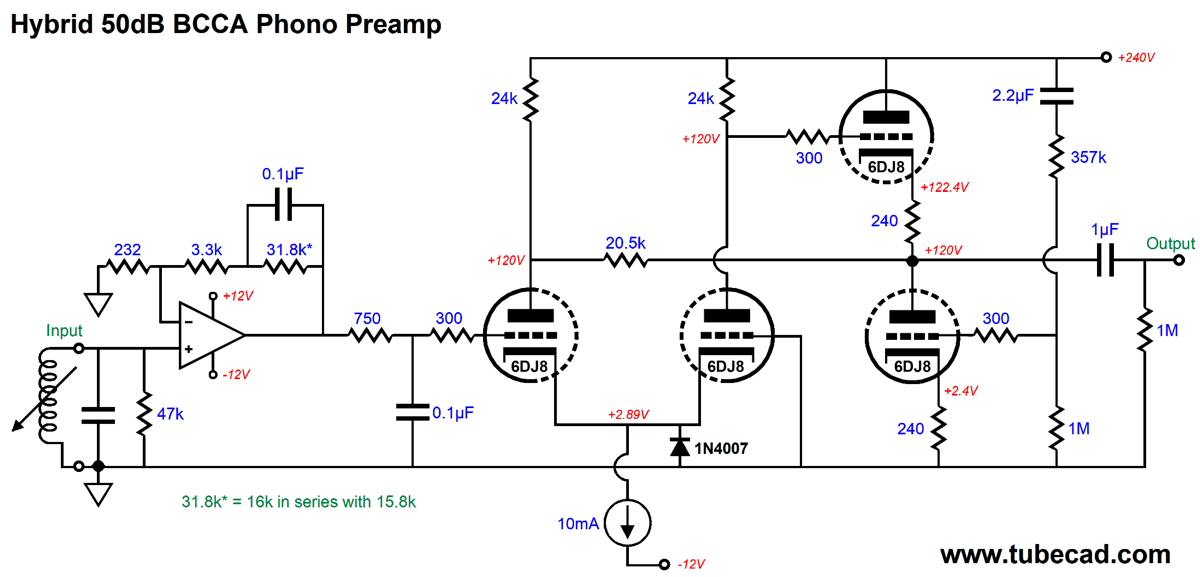
Here we see a Broskie cathode-coupled amplifier (BCCA) receive a flat input signal. This circuit makes use of the -12Vdc bipolar power supply rail to terminate the 10mA constant-current source. The Aikido cathode-follower (ACF) output stage scrubs away the ripple through the 357k and 1M two-resistor voltage divider. The 20.5k resistor reduces the input triode's grid-to-plate capacitance. The 1N4007 rectifier limits the input 6DJ8 cathodes to no more than -0.7V of negative voltage at start-up. While I like the look of this phono preamp, I wondered if I could reduce the tube count. I could.
Once again, the tube portion of the circuit receives a flat input signal. The OpAmp drives the 2N4403 PNP transistor, which in turn drives the 6DJ8's cathode. This is grounded-grid amplifier with Aikido mojo enhancement, as the 33µF capacitor and the two-resistor voltage divider inject enough of the power-supply noise to create a noise null at the cathode follower's output.
High-Voltage Solid-State Shunt Regulator
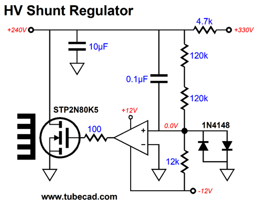
The OpAmp and the MOSFET complete a inverting amplifier, so the OpAmp's non-inverting input is effectively an inverting input for the shunt regulator. Thus, any power-supply noise will be relayed by the 0.1µF capacitor and compared to ground, which is the regulator's input signal. The OpAmp's high open-loop gain will then power the negative feedback to counter the power-supply noise. The STP2N80K5 is a special high-voltage, low-input-capacitance MOSFET in a TO-220 package. The two 1N4148 diodes protect the OpAmp's non-inverting input at turn-on and turn-off, when the 0.1µF capacitor charges up and discharges, by limiting the maximum +/- input voltage to about +/-0.7V. The 12k resistor serves as a constant-current source of sorts, as it sees a constant voltage drop of 12V, so 1mA of current flows through it and the two 120k resistor above it, thereby setting an output capacitor of 240Vdc for the shunt regulator, as the two 120k resistor combine to make 240k of resistance, which against 1mA of current flow creates a 240V voltage drop. We can make an even simpler high-voltage shunt regulator with two transistors.
The 2N4403 PNP transistor is configured as an emitter follower that drives the TIP50's base. The NPN transistor TIP50 is configured as a common-emitter inverting amplifier, which uses its high transconductance to counter the power-supply noise relayed by the 0.1µF capacitor to the 2N4403 PNP transistor's base. Bear in mind that the 4700-ohm series resistor and the 100µF electrolytic shunting capacitor define in themselves a fine RC low-pass filter, so the TIP50 has a lot less work to do, mostly maintaining a fixed DC output voltage. I would give each channel its own shunt regulator.
Patreon
Music Recommendation: English Music for Strings Amazon Music offers it in a high-res format and Prestomusic.com offers the 96kHz, 24-bit lossless FLAC format for only $10, $2 less than the CD-quality version. I know, it doesn't seem to make sense. //JRB
User Guides for GlassWare Software
For those of you who still have old computers running Windows XP (32-bit) or any other Windows 32-bit OS, I have setup the download availability of my old old standards: Tube CAD, SE Amp CAD, and Audio Gadgets. The downloads are at the GlassWare-Yahoo store and the price is only $9.95 for each program. http://glass-ware.stores.yahoo.net/adsoffromgla.html So many have asked that I had to do it. WARNING: THESE THREE PROGRAMS WILL NOT RUN UNDER VISTA 64-Bit or WINDOWS 7, 8, and 10 if the OS is not 32-bit or if the OS is 64-bit. I do plan on remaking all of these programs into 64-bit versions, but it will be a huge ordeal, as programming requires vast chunks of noise-free time, something very rare with children running about. Ideally, I would love to come out with versions that run on iPads and Android-OS tablets.
|
I know that some readers wish to avoid Patreon, so here is a PayPal donate button instead. Thanks. John Broskie
John Gives
Special Thanks to the Special 87 To all my patrons, all 87 of them, thank you all again. I want to especially thank
I am truly stunned and appreciative of their support. In addition I want to thank the following patrons:
All of your support makes a big difference. I would love to arrive at the point where creating my posts was my top priority of the day, not something that I have to steal time from other obligations to do. The more support I get, the higher up these posts move up in deserving attention.
If you have been reading my posts, you know that my lifetime goal is reaching post number one thousand. I have 445 more to go. My second goal is to gather 100 patrons. I have 13 patrons to go. Help me get there.
Only $9.95
The Tube CAD Journal's first companion program, TCJ Filter Design lets you design a filter or crossover (passive, OpAmp or tube) without having to check out thick textbooks from the library and without having to breakout the scientific calculator. This program's goal is to provide a quick and easy display not only of the frequency response, but also of the resistor and capacitor values for a passive and active filters and crossovers. TCJ Filter Design is easy to use, but not lightweight, holding over 60 different filter topologies and up to four filter alignments: While the program's main concern is active filters, solid-state and tube, it also does passive filters. In fact, it can be used to calculate passive crossovers for use with speakers by entering 8 ohms as the terminating resistance. Click on the image below to see the full screen capture.
Tube crossovers are a major part of this program; both buffered and un-buffered tube based filters along with mono-polar and bipolar power supply topologies are covered. Available on a CD-ROM and a downloadable version (4 Megabytes). Download or CD ROM
|
|||


| www.tubecad.com Copyright © 1999-2022 GlassWare All Rights Reserved |