| John Broskie's Guide to Tube Circuit Analysis & Design |
24 December 2022 Post Number 572
(Updated December 26 2022)
It's that time of year, but I will break my long tradition of showing my Aikido-altered photo of Jane Greer (Sep 9, 1924 – Aug 24, 2001), "the woman with the Mona Lisa smile." A few times here before, I have mentioned my tube-based Christmas tree from over twenty years ago, so here is me quoting me.
Today, if I still owned the artificial tree, I would hot-glue LEDs of varying colors into the tube sockets, so the their light would shine up into the tubes. In fact, I own a battery-powered string of LED lights that holds 100 while LEDs. I could probably get away with using a white rubber band on each tube and LED, so no heavy ceramic socket would be needed.
Circlotrons with Inductors
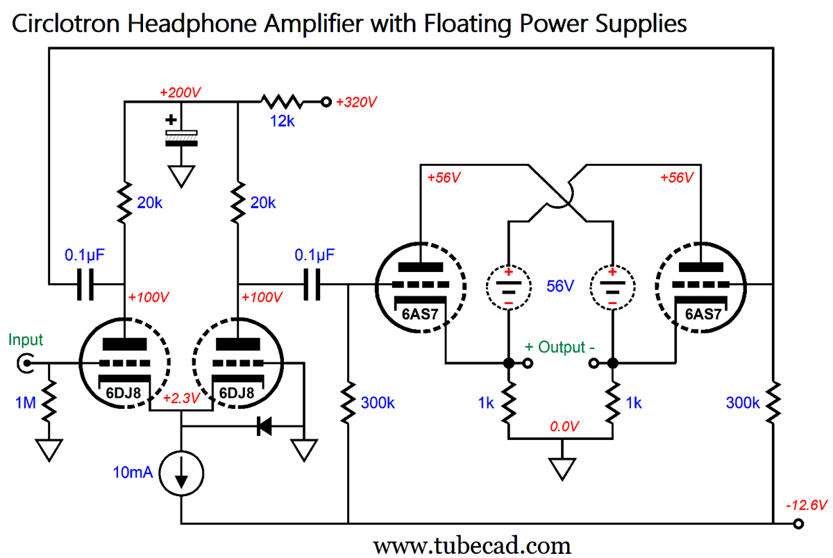
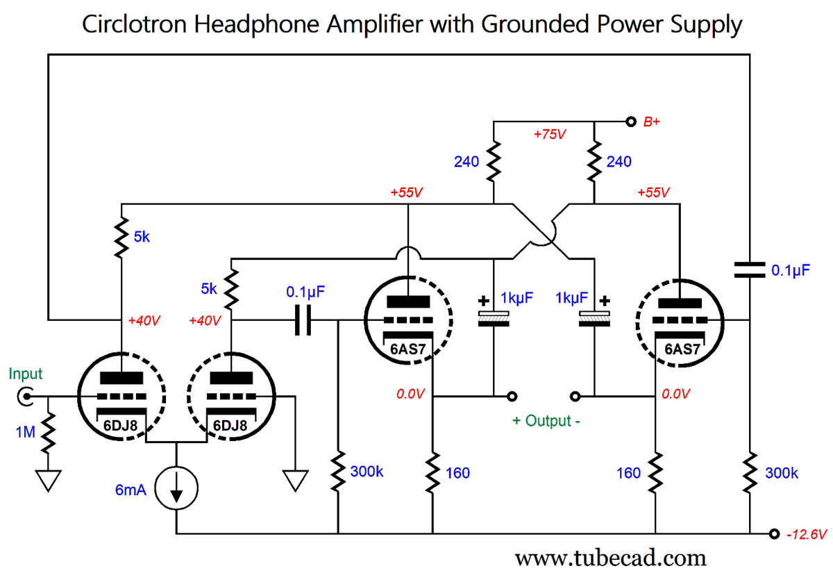
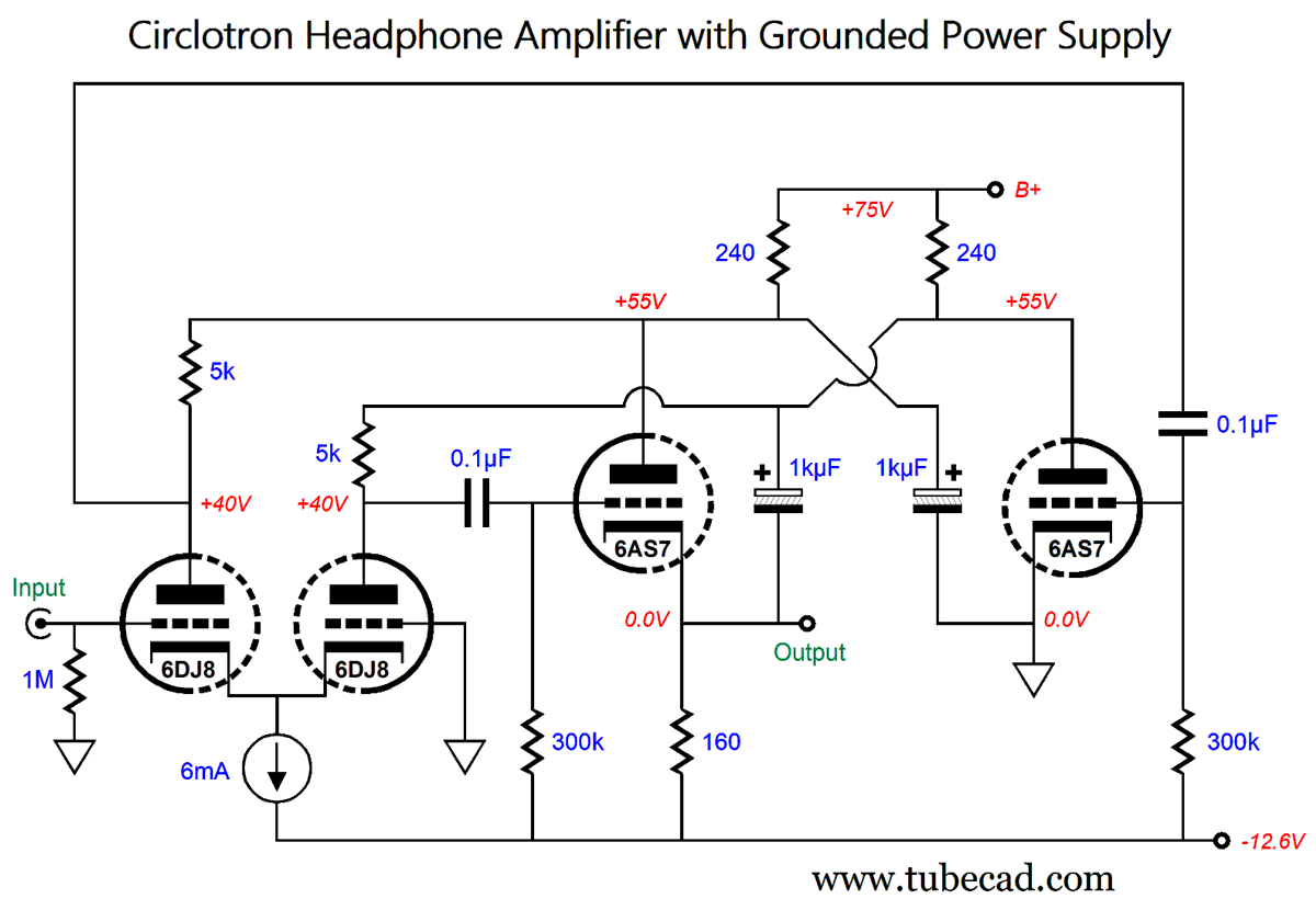
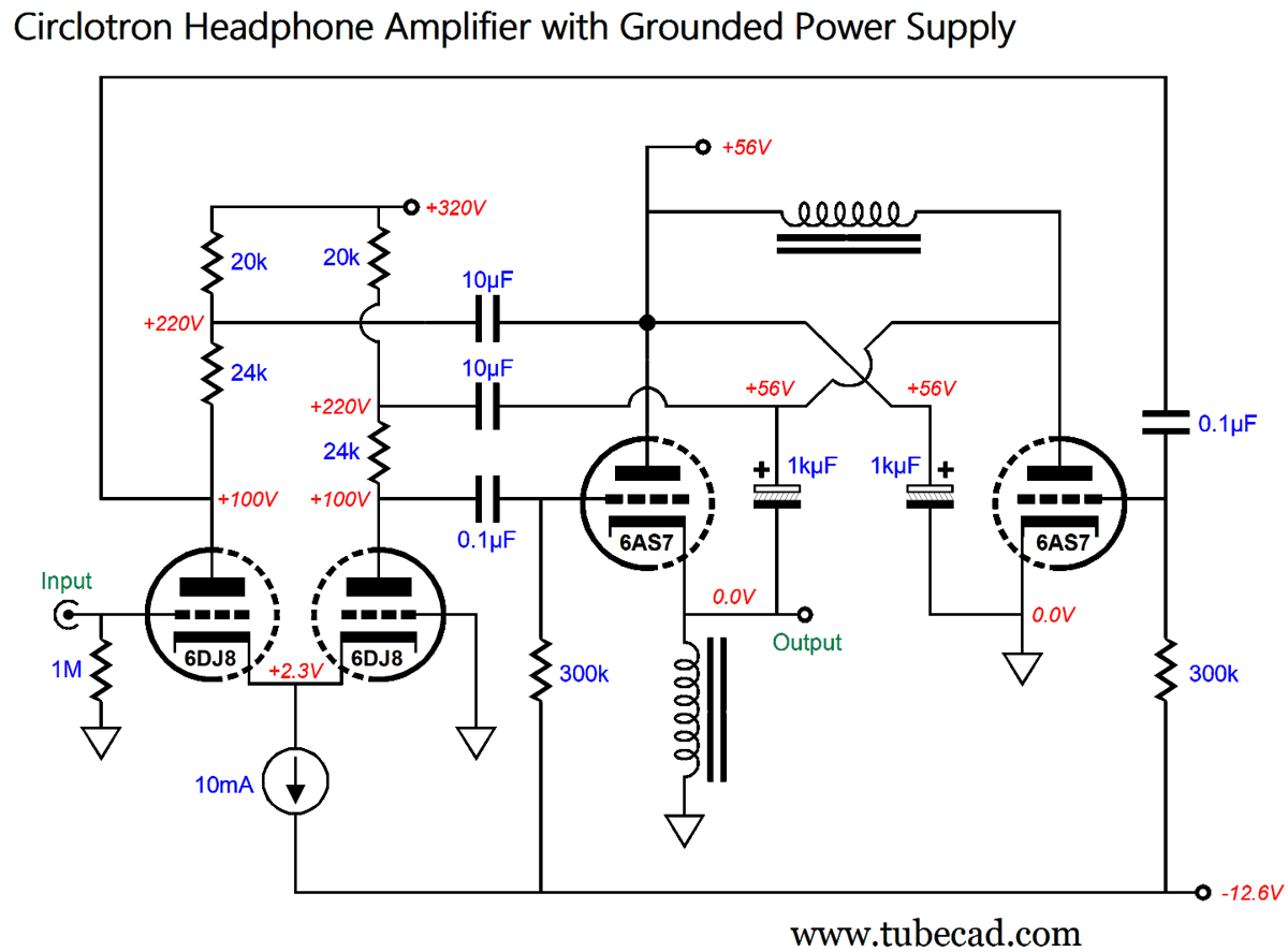
In this post, I we will examine sneaky ways to get around having to provide the two floating power supplies per channel of amplification. The seeming essential aspect of the circlotron circuit turns out not to be the absolute necessity so many imagine it to be. In other words, we can get away with using only one conventional high-voltage power supply, a ground-referenced power supply, even in a stereo circlotron power amplifier. In order to get a feel for a conventional circlotron output-stage, let's look at a simple circlotron headphone amplifier.
The input stage consists of a long-tailed phase splitter that uses a 6DJ8 twin-triode tube and constant-current source to create a balanced output signal to the drive the 6AS7-based circlotron output stage. This long-tail phase splitter offers both gain and a balanced output. (The diode is there to protect the 6DJ8 at startup, as it prevents the 6DJ8 cathodes from being tugged down to the -12Vdc power-supply rail when the tube is cold and not conducting. Once hot, the diode drops out of the circuit.) No negative feedback loop connects the output to the input stage. If less gain is needed, we could swap out the 6DJ8 with 6CG7; if more, a 6AQ8 or 6N1P or 12AT7. If we wanted to drive the headphone amplifier with a balanced input signal, we would use the left 6DJ8 triode's grid as the inverting input. Overall, this input stage is extremely simple and splendidly effective.
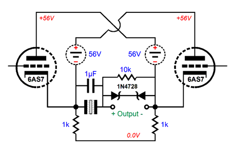
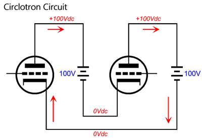
The standard circlotron's magic requires two floating power supplies. A floating power supply is one that is not directly connected to ground, which I represent with the dashed-lined circles.
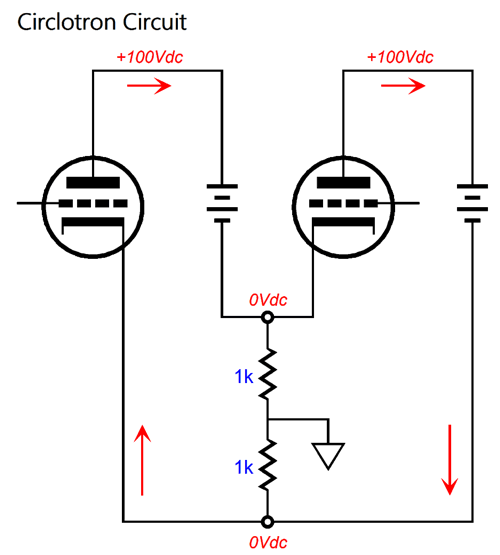
Indeed, if 56V rechargeable batteries were sold, we could use them as floating power supplies. The two 1k resistors perform no other function than to place the amplifier's ground-reference mid load.
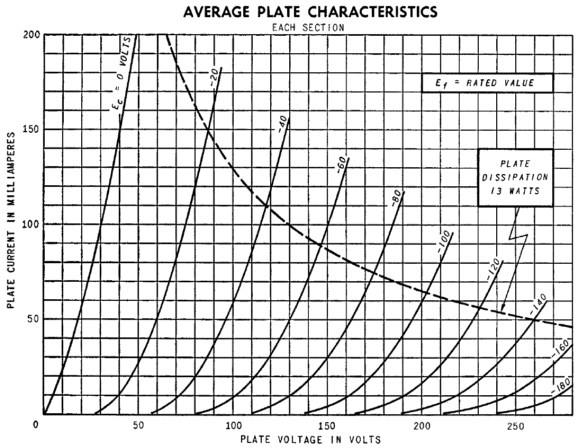
The 6AS7 is brutish twin-triode tube with an octal base that is often used in big OTL power amplifiers. The 6AS7 offers a wee amplification factor (mu) of only 2 and a relatively low plate resistance (rp) of 280 ohms.
In addition, the 6AS7 can deliver a staggering amount of current flow with a comparatively low B+ voltage (for a tube that is, but an absolutely paltry amount compared to a solid-state device). Sadly, we must pay for the high current flow by feeding the 6AS7's 6.3V heater element 2.5A of current, which far exceeds the current needed to power a KT88 heater. Assuming a stereo amplifier, we can place the two 6DJ8 heaters in series and the two 6AS7 heaters in series, and then both heater strings can be powered by the -12Vdc power-supply rail voltage. By the way, I have to point out that this design is not meant to be a recommended project for actual headphone powering, rather it is a design example to understand the basic circlotron operation. If we did want to build an actually useful circlotron headphone amplifier based on this design, then we would have to make it, at the very least, safer. In short, direct-coupled OTL outputs are dangerous, as a jiggled tube or an internal tube arc will toast your extremely expensive headphones in a flash. One workaround is to add an output coupling capacitor and voltage-limiting zeners.
A 1N4728 zener breaks at 3.3V and presents a forward-biased voltage drop of about 0.7V, so the two in opposition create a 4V bidirectional voltage clamp. The 10k resistor and non-polarized electrolytic capacitor save the delicate headphone driver from seeing any DC offset voltage. The 1µF film capacitor is just frosting on the coupling capacitor cake. Okay, let's move on to eliminating the two floating power supplies. Why? Because they are a pain, especially if you plan on using tube rectifiers. Ideally, we want only one high-voltage power-supply rail that can power two channels of amplification. Here is one possibility.
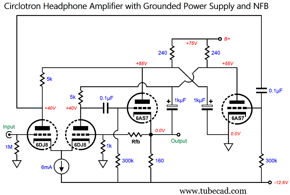
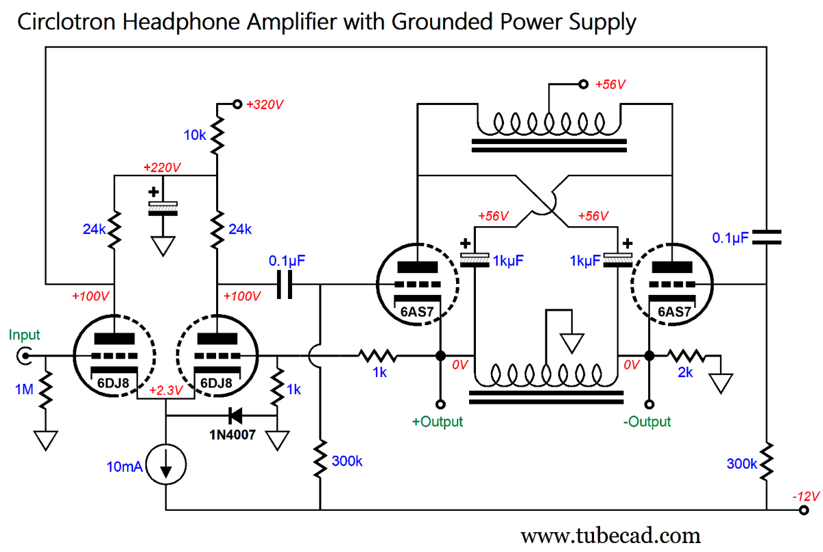
A B+ voltage of only 75Vdc is used, and the constant-current source's current flow has been lowered to 6mA. The two 1kµF capacitors take the place of the usual two floating power supplies. Once charged up, these two capacitors act like batteries and offer an AC shunting across their ends. The essential addition is the two 160-ohm resistors, which provide the needed current path for the current flow from the negative power-supply rail through the tube cathodes and to charge the two 1kµF capacitors. These resistors will dissipate 1W at idle, so 2W types should be used. (If we want to be extra bold, we could replace the resistors with two constant-current sources.) Effectively, the circlotron output stage is already loaded by the 240-ohm and 160-ohm resistors, which make a combined load resistance equal to (240 + 240) || (160 + 160) or 192 ohms. Once again, this is an overly simplified design, so grid-stopper resistors and an output coupling capacitor and zeners are needed for safe use. This design assumes balanced output drive of the headphones. If we prefer unbalanced (normal) powering, we can alter the circuit thus:
Note that the right 6AS7 triode's cathode is grounded, so only one 160-ohm resistor is needed. Also note that the output is now unbalanced. What happens to the circlotron magic? It's still there, although the ground no longer falls mid load, but at one end. The two 6AS7 triodes still see all the same voltage and current swings that they would in the previous design. In addition to our being able to use conventional headphones with three-ringed prongs, this design allows us to add easily a negative feedback loop.
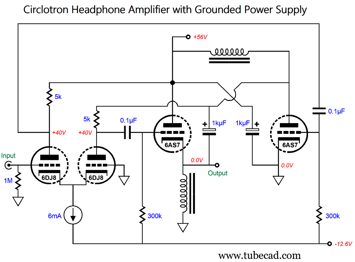
The added 1k resistor and the Rfb resistor complete a negative feedback loop that allows us to lower the gain and distortion and output impedance. That last reduction (output impedance) is important, as the 6AS7-based circlotron output impedance is about 40 ohms, which is good for 300-ohm headphones, but not for 32-ohm headphones. The single 160-ohm resistor could be replaced by a constant-current source, which would help unload the output stage. A better substitution might be to use an inductor in place of the resistor and replace the two 240-ohm resistors with a single inductor.
The inductors sees a net unidirectional DC polarizing current flow, thus an air-gap is needed in their construction. (Remember, the circuit shown is for instruction; real inductors present a DC resistance [DCR], so a matching amount of resistance would be needed at the right triode's cathode and the left triode's plate to balance the DC offset.) The B+ voltage has been reduced to 56Vdc, which could be supplied by a desktop switching power supply. Moreover, the negative power-supply rail -12Vdc could be provided by an external switching power supply. This would allow for two-stage turn-on, where the heaters get their voltage first, and then the tubes get their B+ voltage.
Much like the constant-current source, the inductor passes the DC current flow while presenting a high impedance. Well, at least it does if its inductance is high enough. I would use a 500mH to 1H inductor. We can get extra fancy by running the input stage at a much higher B+ voltage.
The 6DJ8 performs better with 100V on its plate and with 24k plate resistors. It may not look like it, but in this design and the two previous designs, the input phase splitter has been correcting for the inherent unbalanced drive requirement for the output triodes, as the triode on the right has a grounded cathode, while the triode on the left has its cathode swing up and down with the output signal. This explains why the two 10µF capacitors are not grounded. A better arrangement is the following.
Both capacitors see the same voltage differential and the phase splitter still maintains a balanced drive for the output stage, but an improved PSRR obtains. Returning to a balanced output circlotron circuit, we can use a center-tapped inductor to provide the current flow from ground through the output triodes.
The two 1k negative-feedback-loop resistors set a differential gain of 1:4 or +12dB. In other words, 1Vpk of input signal results in 4Vpk of differential output voltage swing across the headphone driver. The added 2k resistor just helps balance the output stage. Much like an output coupling capacitor, the center-tapped inductor is inherently safe. For example, if an output triode shorted from cathode to plate (which is very rare), the headphones would probably survive, as the driver would be shorted by the inductor's DCR resistance. In other words, a huge voltage spike would develop, but then relapse into a small DC offset voltage. Thus, we should add the two-zener protection diodes, as it would limit the voltage spike to a few volts. By the way, we could replace the two center-tapped inductors with one flat-pack power transformer.
A power transformer with two primaries and two secondaries, all with an equal input and output voltage, i.e. 115Vac, would prove a worthy choice.
Once again, since no net unidirectional DC polarizing current flows, no air-gap is needed in the transformer's construction, which explains why an off-the-shelf power transformer could be used. The reason behind the flat-pack design is that each winding offers the same DCR, which is not true of most transformers where the winding rest atop each other. Having introduced the power transformer, we might as well look into using a proper output transformer.
The output transformer offers many advantages, such as safety and lower distortion and output impedance. Let's be frank here: a 32-ohm load is an onerously low load for any triode, even a 6AS7. With a winding ratio of just four-to-one, the impedance ratio becomes one-to-sixteen, so the 32-ohm headphone driver appears as a 512-ohm load to the output triodes. Indeed, we could use a more linear output triode, such as the 6H30 or ECC99, both of which offer more transconductance than the 6AS7, thus a lower output impedance. As an added bonus, these alternative tubes draw much less heater current. With this arrangement, we can ground one end of the secondary, so unbalanced output results, or we can run the output balanced. We can also add a tap to the secondary so that low-impedance and high-impedance headphones can be driven, which is a good option to have on hand. Another variation would be to use two output transformers, thereby eliminating the need for the top center-tapped inductor.
The two secondaries are wired in parallel, as the two 1kµF capacitors ensure that the same output signal appears on the triode's plates as on their cathodes, albeit DC voltage shifted. What about PSRR, do the output transformers shield the output triodes from B+ voltage ripple? Well, they sort of do, as 50% of the ripple will appear at the bottom the cathodes and at the plates. This ripple should not make to the secondary, however, as a transformer is an intrinsically differential device that ignores common-mode AC signal, which the ripple definitely is. Having come this far, we might as well examine one last possible variation.
The output transformer holds two ultra-linear taps, which allows us to develop extra big output voltage swings at the ends of the primary, which we can use to drive electrostatic headphones. Note the increase B+ voltage, which is needed as we need to develop large cathode voltage swings. In fact, the 6DJ8 input tube should be replaced with a 12AX7, as we need all the gain we can get from the input stage. This arrangement would allow us to have a universal headphone amplifier that could drive either electrostatic headphones or high- or low-impedance dynamic headphones.
|
I know that some readers wish to avoid Patreon, so here is a PayPal button instead. Thanks.
John Broskie
John Gives
Special Thanks to the Special 79 To all my patrons, all 79 of them, thank you all again. I want to especially thank
All of your support makes a big difference. I would love to arrive at the point where creating my posts was my top priority of the day, not something that I have to steal time from other obligations to do. The more support I get, the higher up these posts move up in deserving attention.
If you have been reading my posts, you know that my lifetime goal is reaching post number one thousand. I have 428 more to go. My second goal was to gather 1,000 patrons. Well, that no longer seems possible to me, so I will shoot for a mighty 100 instead. Thus, I have just 21 patrons to go. Help me get there. Thanks.
Support the Tube CAD Journal & get an extremely powerful push-pull tube-amplifier simulator for TCJ Push-Pull Calculator
TCJ PPC Version 2 Improvements Rebuilt simulation engine *User definable
Download or CD ROM For more information, please visit our Web site : To purchase, please visit our Yahoo Store: |
|||
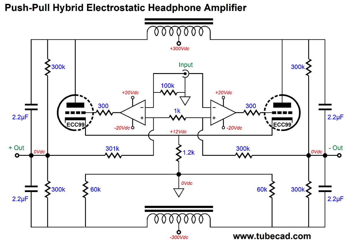
A Solid-State Electrostatic Headphone Amplifier
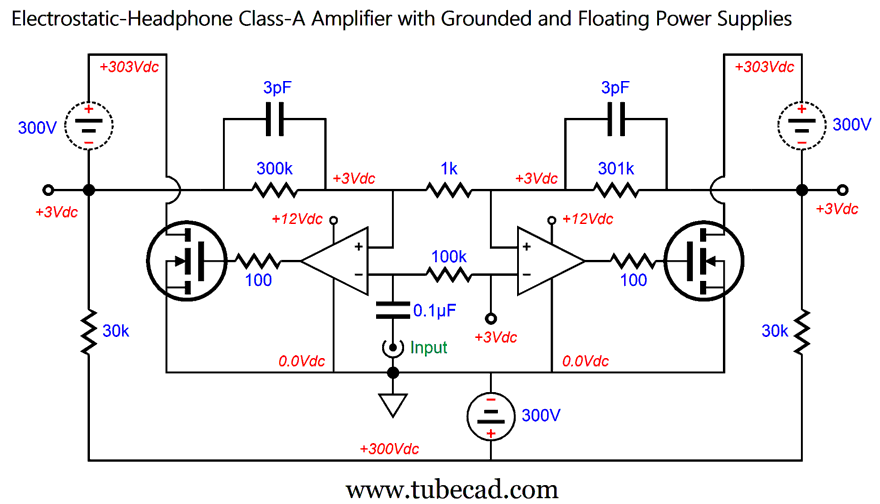
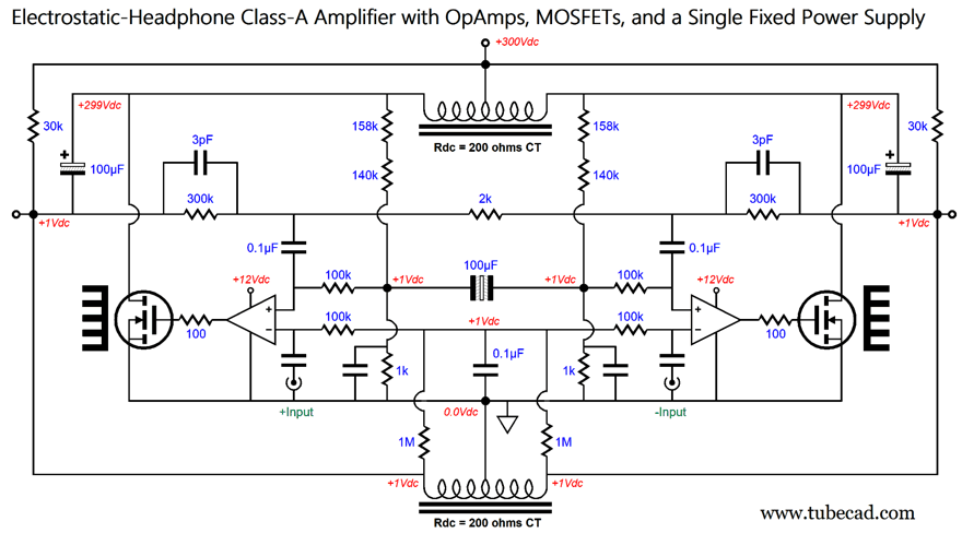
This hybrid electrostatic headphone amplifier uses two bipolar power supplies, one with +/-300Vdc rails for the triodes and the other with +/-20Vdc rails for the OpAmps and tube heaters. The design we will go over uses high-voltage MOSFETs in place of the ECC99 triodes and a single 12Vdc power supply in place of the +/-20Vdc bipolar power supply. In addition, the +/-300Vdc bipolar power supply has been replaced by four floating 300Vdc power supplies. 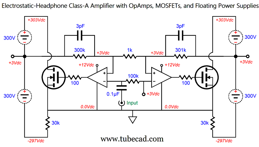
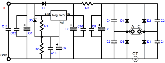
Electrostatic headphones require about a 500V differential voltage swing, so each stator will see +/-250Vpk of voltage swing. How do the two OpAmps accomplish this and still run under only 12V? The secret is found in the MOSFET sources being grounded and the four floating power supplies. By the way, I should first show just how easy it is to create a floating high-voltage power supply. 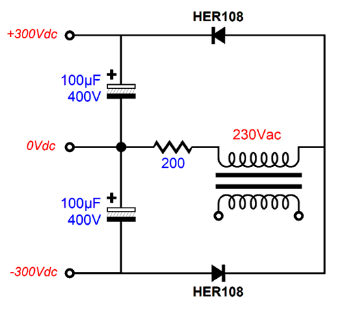 The 230V secondary would normally develop about +/-325Vdc with the voltage-doubler circuit, but the 200-ohm resistor and the 10mA current draw from the MOSFET and its 30k load resistor work to drop the voltages to +/-300Vdc. I might as well show the 12V regulated power supply. 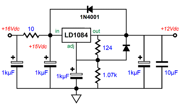 This is a better than average voltage regulator, as the low-dropout voltage gets a pre-filter RC filter that greatly improves the PSRR, especially at higher frequencies. By the way, if this circuit looks familiar, it's because it is basically the circuit used in my LV-Regulator.
Returning to the amplifier circuit, the two OpAmps seemingly are disoriented, the inputs flipped wrongly; they aren't. What is going on is that the MOSFET inverts the signal at its gate at its drain, much like a triode inverting its grid signal at its plate. Thus, the OpAmp and MOSFET combined result in an inversion of the OpAmp inputs, the non-inverting becoming the inverting input, the inverting the non-inverting. Therefore, we must use what seems to be the wrong inputs. What is so dang clever about this design is that the OpAmps do not need a bipolar power supply and the circuit auto-biases, which is made easy due to the class-A operation of the output devices. Auto-bias results from the 3V reference voltage applied to both inputs and the negative feedback loops that establish the same 3V DC offset at each output, as the only way the 3V offset come about is if the 30k resistors see a 297V voltage drop. With electrostatic headphones, the 3V DC offset makes no real difference. In addition, the DC offset helps out the OpAmps, as their internal input stage needs some voltage padding between its inputs and its negative power-supply-rail voltage. (Some OpAmp can accept input signal below their negative power-supply-rail voltage, as they use FET-based input stages.) The relatively low B+ voltage for the OpAmps (12V) imposes a welcome maximum voltage limit on the MOSFET's gate-to-source voltage (about 10Vmax with most audio-grade OpAmps), which is well within the typical 20V maximum voltage. Both halves of the amplifier deliver a gain of 1:301, with the left side being in phase with the input signal. In other words, a tad less than 1Vpk is enough to drive the amplifier to full balanced output. Okay, now let's look at how I would actually build the design.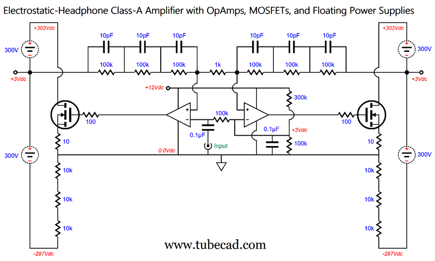 Functionally, this arrangement is identical with the previous schematic. The negative feedback loop's three 100k resistors add up to 300k. The three 10pF capacitors are effectively in series, so their capacitances do not add up as resistances would, but reduce to their parallel value, which is 3.3pf. Each 10k resistor must dissipate 1W at idle, so 2W resistors should be used. What if we got rid of all the 10k resistors? If nothing else, we would halve the amplifier's dissipation.
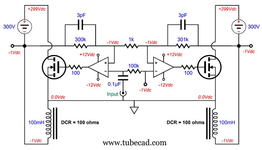
The two inductors take the place of the 10k resistors and allow us to lose two floating power supplies. (A center-tapped inductor could be used in place of the two separate inductors.) We exploit the inductor wire's DCR to monitor the current flow through the MOSFETs. Note that the inductors experience a 1V voltage drop at idle, the result of 10mA of current flow against the 100-ohm DCR. This creates a -1V potential that the OpAmps will strive to establish, as we have fed the OpAmps a -1V reference voltage. Also, note that we can no longer get away with powering the OpAmp through a monopolar power supply, but must now use a bipolar power supply. Thus, we lost two floating power supplies, but had to add a -12V power-supply rail. In other words, a great deal, as the high-voltage floating power supplies are a much bigger pain to implement. I imagine that this last circuit has provoked much head-scratching. Floating power supplies do that. The circlotron circuit uses two floating power supplies that so confuse many audiophiles that they believe all sorts of crazy nonsense; for example, the circlotron must, ipso facto, be a class-A amplifier, no matter how little idle current flows. The key point to a floating power supply is that it is not directly connected to ground. A key point to remember about ground is that—where it falls in a circuit—is up to us. Ground is not an electrical or electronic part; it is a voltage reference point. We cannot go to an electronic-parts store and buy a new ground, one with better specs or a fancier enclosure. (In the non-reality-based world of high-end audio, however, you can buy a new super-expensive "ground," for a mere few thousand dollars! Audio-grade "grounds" that are chock full of electrons, unlike the lousy ground in in your existing electronics, which is embarrassingly meager in electrons.) The following illustration shows that the difference between the two circuits is where we have chosen to place the ground, our voltage reference point.
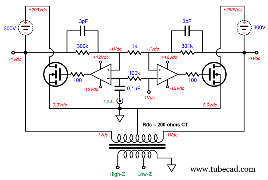
The circuit shown on the left places the ground at MOSFET's source; the one on the right, at the voltage source's negative terminal, thereby making the voltage source no longer floating. In both circuits, the MOSFET experiences the same voltage drop and current flow and dissipation, as does the inductor. Okay, now let's replace the two inductors with an output transformer, so both electrostatic and dynamic headphones can be driven.
Imagine a winding ratio between the low-Z tap on the secondary to the primary of 100:1, so that electrostatic headphones get a hundred times bigger voltage swing than do 32-ohm headphones; for example, 500V peak-to-peak for the electrostatic headphones and 5Vpk for 32-ohm headphones. By the way, a winding ratio of 100:1 implies an impedance ratio of 100² or 10,000 to 1; thus, a 32-ohm load is reflected to the primary as a 320k load. Another by the way, since this is push-pull, class-A amplifier that dissipates 6W at idle, we can expect to get close to half the dissipation as output power; in this design example, about 3W. To get 3W of power into an 8-ohm load requires 6.9Vpk. If we divide 500V by 6.9V we end up with 72, which would be the required winding ratio to drive an 8-ohm loudspeaker. A winding ratio of 72:1 implies an impedance ratio of 72² or 5,184 to 1; thus, an 8-ohm load reflects to the primary as a 41.5k load. (Imagine a nice computer speaker.) I love the idea of a dual-use headphone amplifier that I could use to power computer loudspeaker or electrostatic headphones. Ready for this, we still have not arrived at my old circuit that I found. Remember how this section began: "Having just finished writing the previous section, I went hunting for a similar circlotron circuit, but one that used OpAmps and MOSFETs." I had to first limber up your mind, otherwise the following circuits would make no sense.
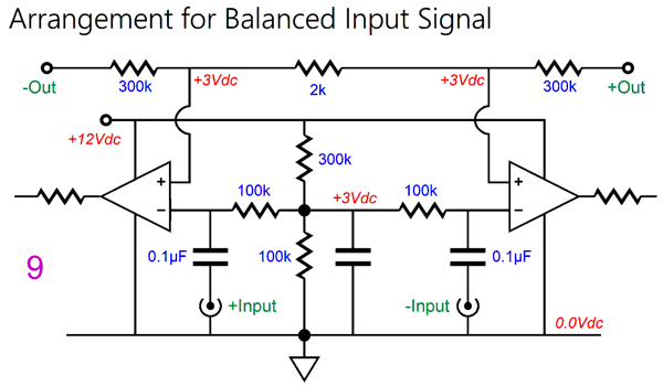
Two inputs, two input coupling capacitors, one two-resistor voltage divider to establish the needed 3V reference voltage. The 1k negative feedback resistor is now 2k in value, as the balanced input signal effectively halves the needed gain. In other words, most balanced input signals are differentially twice the unbalanced signal. Okay, let's return to the previous version that accepted an unbalanced input signal, but redrawn.
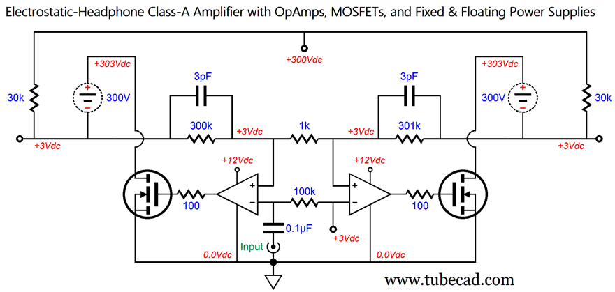
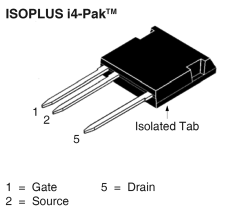
This circuit offers the exact same performance as the version with four floating power supplies, but only uses two: a substantial savings in hassle, weight, and PCB real-estate. By the way, this exact same topology could be used to make a power amplifier for driving electrostatic loudspeakers, requiring no more than a far greater B+ voltage and a higher voltage MOSFETs and higher idle current. In other words, more of everything other than the OpAmps and their low-voltage power supply. Today, we can buy truly high-voltage MOSFETs, which come in special packages that prevent arcing from its pins.
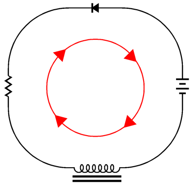
Now, the hard task: explaining how the circuit works. A circuit is something that completes itself, like an oval racetrack. The straight racetrack used to for dragstrip racecars does not count, as it does not start and finish at the same spot. Obviously, "circuit" and "circle" share a common etymology. Here is a simple circuit that nicely defines a circle of current flow.
The battery provides the voltage potential brings current flow into being. The inductor impedes AC current flow, but readily passes the DC current flow. The resistor limits the current flow. And the diode offers unidirectional current flow. The circle of current flow shown follows the flow of electrons, not the "conventional" direction of current flow. It's not much of a circuit, but it does serve to point something interesting out—namely, we can move the electrical components around the circle without altering the current flow's direction or amount. Think beads on a string necklace. Importantly, while we can freely move the diode about the circle, going either clockwise or anticlockwise, we cannot flip the diode without also flipping the battery. Now, let's return to the arrangement used in the version with four floating power supplies.
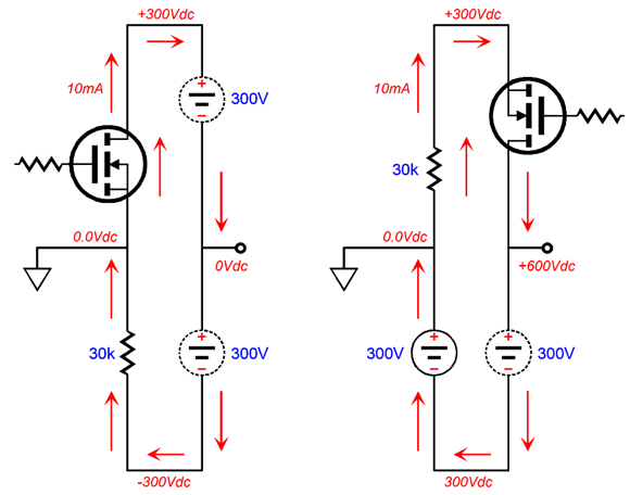
In the circuit on the left, the N-MOSFET conducts 10mA of current that travels through the two 300V floating power supplies and the 30k load resistor. Note that no current flows in or out of the ground. If we move the ground connection to the other side of the 30k resistor, as shown in the circuit on the right, we get the following voltage relations, but the same 10mA current flow and the same 300V voltage drop across each device. This circuit only holds one floating power supply, as the other power supply is now directly attached to ground. So far, no one will argue that both circuits achieve the same circular flow of current. But what if we spin the 30k resistor around in an anticlockwise motion so that it now attaches to the MOSFET's drain, rather than its source?
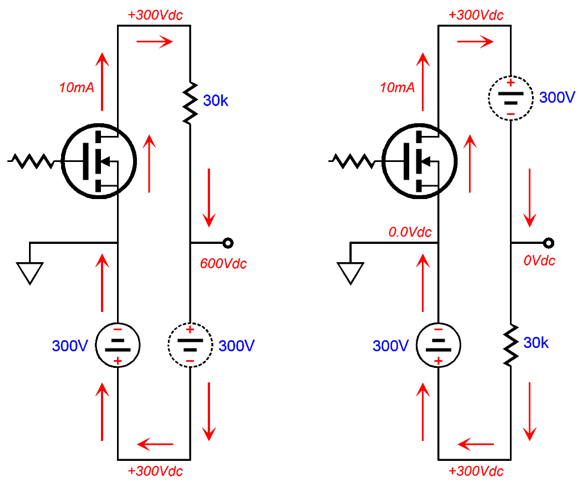
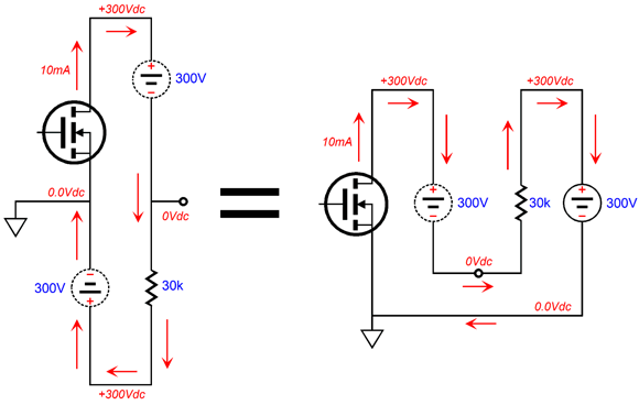
In the circuit on the left, we see the resistor moved around the current path. Note that the output no longer can provide an AC output signal, as it terminates into the new 600Vdc B+ voltage. No matter how much or how little current the MOSFET draws, the output voltage remains a constant 600V. In contrast, the circuit on the right moves the resistor in between the two power supplies, and this arrangement allows an AC output signal. If the MOSFET draws more current, the output will swing negatively. If it draws less current, the output will swing positively. The next step is to simply redraw the circuit without altering any of the voltage relationships or direction of current flow.
Both circuits are the same, but the one on the right causes mental unease in some. On the other hand, the following circuit seldom does.
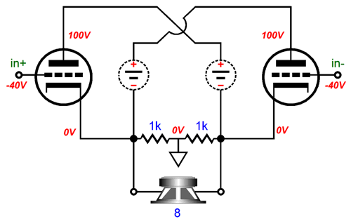
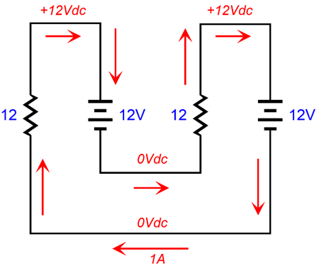
Imagine two car batteries and two power resistors. Each resistor sees a 12V voltage differential, so 1A of current flows. We can replace the two resistors with two triodes and up the battery voltages to 100V.
The voltage has gone up tenfold, but the current flow has gone down tenfold, assuming a robust triode, such as the 6AS7. Drawn this way, we would not recognize the circlotron circuit, but it is there nonetheless. If we add the usual two 1k resistors, it might be more readily seen.
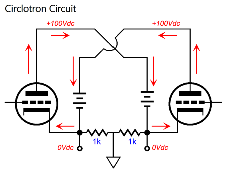
The two resistors allow us to place the ground mid output load, which is a defining feature of the circlotron. Still don't see it? Well, here is the exact same circuit redrawn.
Classic circlotron. Note that no current flows through the resistors at idle. I hope everyone sees how amplifiers with floating power supplies are not as paradoxical as they may seem at first. Now, we move on tube-based variations on this topology.
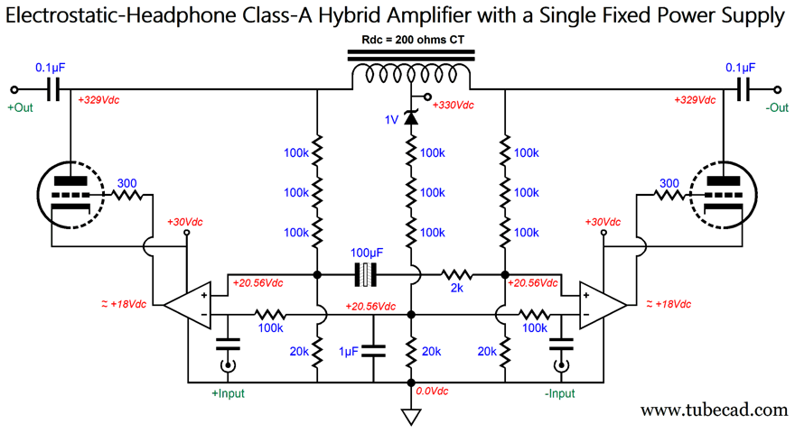
The N-MOSFETs have been replaced by ECC99 triodes and two floating power supplies are used along with an output transformer, which allows dual use: the driving of either electrostatic or dynamic headphones. The triodes idle at almost 10mA, so their plate dissipation is almost 3W per triode. The OpAmp is powered not by the 12V regulated power supply, but by a -30V regulator, which will also power the ECC99 heaters (both placed in series and fed by an 11-ohm power resistor). By the way, if we are willing to forgo the DC-coupled outputs, we could use the output transformer in a more conventional position.
It may look complex, but is basically just a push-pull tube output stage driven by two OpAmps. The fanciest aspect is the auto-bias scheme, wherein the strict class-A operation allows the OpAmps to monitor the voltage drop across the 10-ohm cathode resistors. In addition, the OpAmps control the AC output after the output coupling capacitors. Note the +5V and -25V bipolar power supply rail voltages.
The Big Reveal
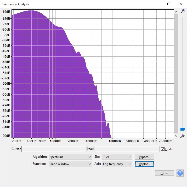
The balanced outputs are DC coupled to the electrostatic headphones stators, with an entirely ignorable 1Vdc offset. Remember, an electrostatic speaker is just a capacitor with a diaphragm wedged in between the stators. In other words, the only resistance the electrostatic driver exhibits is that of the air in between the stators. Electrostatic loudspeakers do present a frequency-dependent impedance, however, as do all capacitor loads. In order to charge and discharge a capacitor 20,000 times in one second requires current. The amount of current needed depends on the amount of capacitance being driven and voltage imposed. The frequency and capacitance and current are all interrelated in slew-rate. Slew-Rate = (2 × pi × Freq × Vpk) / 1,000,000 where the slew-rate is in V/µS. And current equals slew-rate against capacitance. I = Slew-Rate x Capacitance where the slew-rate is in V/µS and the capacitance is in µF. Do the math and you see that the 170pF load of capacitance requires at 500Vpk at 20kHz a slew-rate of 62.83, which further implies a current peak swing of 10mA. A class-A electrostatic amplifier that idles at 20mA can deliver a peak current swing of 20mA, so we are doubly safe in this designs. I must point out that we do not actually need full-power bandwidth out to 20kHz, as 6kHz to 8kHz is sufficient. How so? Run a spectrograph of your favorite music album and you will see most of the big signal amplitudes are below 600Hz, with far less showing up at high frequencies, with almost no signal at 20kHz. Here is an example taken from Chopin's No. 1 in C Major Prelude performed by Martha Argerich, a 24-bit 192kHz recording.
Each drop of -6dB equals a halving of the signal level. A drop of -60dB equals 1/1000 as much signal level. I have conducted many listening tests with my Stax electrostatic headphones over the past decades and I have been constantly surprised by how much I could back off the idle current flow and still get excellent sound. By the way, I have a reputation for being a hard-core heavy-foot when it comes to idle current in tube-based circuits. Where a friend would run a 6BX7 triode with 1mA of plate current, I would run 10mA to 20mA. Thus, my reducing the idle current ran against my inclination. In other words, if I were to build any of the MOSFET-based designs shown here, I would stick to 10mA idle current for each MOSFET. But if I were building an ECC99-based hybrid design, I would run only 5mA per triode, so as to extend the tube life dramatically. The circuit auto-biases the high-voltage MOSFETs so that they experience the same current flow at idle as the two 30k load resistors. How this important trick is accomplished takes some explaining. We start at the bottom center-tapped inductor whose center-tap is grounded. Current flow up through inductor's wire and the two 30k load resistors up to the 300V B+ voltage. Copper wire presents some resistance, which in this design is a feature, not a bug. The inductor's DCR is used as a current-sense resistance that allows us to monitor the current flow through the 30k resistors. The two 1M resistors pass along the voltage drop across the inductor's windings. The 0.1µF filters away what little AC signal is present at the resistor nexus. Yes, the balanced outputs will swing +/-250V, but they do so in anti-phase to each other, so at the nexus, the AC signal should cancel, leaving just the DC voltage-drop. Now, we move to the top center-tapped inductor. This inductor is also made with copper wire, and it, too, will experience a voltage drop due to the current flow from the MOSFETs. We need to ensure that the MOSFETs draw the same current as the 30k load resistors. Two resistor-based voltage dividers are used, one for each end of the top inductor. The voltage dividers outputs are bridge by the 100µF non-polarized electrolytic capacitor, which will allow the anti-phase AC signals to cancel and null, leaving the DC voltage for the OpAmps to compare against the voltage drop created by the current flow through the bottom inductor windings. If the MOSFETs draw too much current, the OpAmps will effectively see a negative DC signal at their non-inverting inputs, which will force their outputs negatively, which in turn will make the MOSFETs reduce their current flow until the two voltage drops match each other. Negative feedback, in a nutshell. This auto-bias arrangement is not an absolute arrangement wherein the MOSFET always see a fixed 10mA current flow at idle, but rather a dynamically adjusting bias that adapts to varying B+ voltages. For example, if the wall voltage falls by 10%, so, too, will the current flow through the 30k resistors and MOSFETs. If you think that this is all a lot of work to get DC-coupled outputs, you are right. Using two output coupling capacitors would greatly simplify our efforts. The problem with output coupling capacitors in an electrostatic power amplifier is that capacitors can sing; the bigger the voltage swings, the louder they sing. In other words, the capacitors act like tiny electrostatic loudspeakers. The degree to which a capacitor sings depends on its construction, not its cost or perceived tone or status. (I should by a stethoscope and conduct some tests of various capacitors.) Let's assume that we enjoy owning dead-quiet coupling capacitors, so the following design can be entertained.
Like the previous design, this electrostatic headphone amplifier requires a balanced input signal. Unlike the previous design, this amplifier maintains a fixed-current flow at idle, as the OpAmps strive to impose the same voltage drop across the center-tapped inductor windings as across the zener diode (or IC voltage reference). Note the 2k negative feedback resistor in the middle, which is double the 1k resistor used in the previous designs, the result of using a balanced input signal. The 100µF non-polarized electrolytic capacitor was added so that each half of the amplifier is DC isolated from the other, which will better ensure that each triode draws the same current at idle. As you can guess, I could go on and on, but it is getting late and I have dogs to empty; besides, I am well over 5,000 words. Thus, I must rest the urge to continue to go boldly where no solder-slinger has before.
Music Recommendation: A Very Chimytina Christmas I discovered the album at Amazon Music Service in 24-bith, 44.1kHz. It does not seem to be available at Qobuz, sadly.
//JRB
Did you enjoy my post? Do you want to see me make it to post 1,000? If so, think about supporting me at Patreon.
User Guides for GlassWare Software
For those of you who still have old computers running Windows XP (32-bit) or any other Windows 32-bit OS, I have setup the download availability of my old old standards: Tube CAD, SE Amp CAD, and Audio Gadgets. The downloads are at the GlassWare-Yahoo store and the price is only $9.95 for each program. http://glass-ware.stores.yahoo.net/adsoffromgla.html So many have asked that I had to do it. WARNING: THESE THREE PROGRAMS WILL NOT RUN UNDER VISTA 64-Bit or WINDOWS 7, 8, and 10 if the OS is not 32-bit or if it is a 64-bit OS. I do plan on remaking all of these programs into 64-bit versions, but it will be a huge ordeal, as programming requires vast chunks of noise-free time, something very rare with children running about. Ideally, I would love to come out with versions that run on iPads and Android-OS tablets. |
||||


| www.tubecad.com Copyright © 1999-2022 GlassWare All Rights Reserved |