| John Broskie's Guide to Tube Circuit Analysis & Design |
October 17 2024 Post Number 609
Converting Stereo to Mono
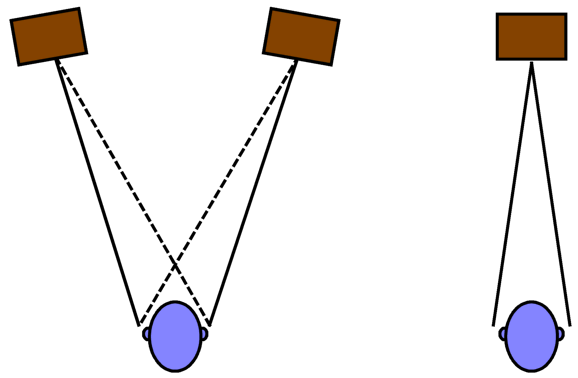
Then there are those who have no interest in stereo imaging, preferring the sound from a single loudspeaker. Others are deaf in one ear; as a result, for them no stereo image is possible. As compensation, imagine the money savings these unfortunate enjoy in having only to buy a single loudspeaker and single a monobloc power amplifier. (In addition, such a one-ear audiophile would encounter only half the spouse-acceptance-factor resistance that two loudspeakers would engender.) Moreover, LP lovers know that mono LPs sound better when played with a mono phono cartridge. In addition, even a stereo phono cartridge will deliver better mono playback when the left and right signals are summed together, as the turntable rumble will largely cancel. In other words, mono can have a place in our sound systems. To create a mono signal from a pair of unbalanced stereo signals is easy enough, as only two resistors are needed.
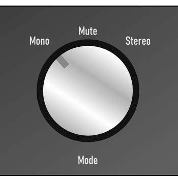
The mute in the center position is a fun addition, especially for those with LP playback, as the cartridge's needle cleaning goes better with muting, as does answering the phone.
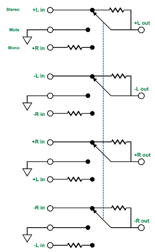
Note that, in the stereo position, no extra resistors are in the signal paths. When in the mute position, the input balanced signal will see four resistors terminating into ground, not ground directly. In the mono position, all eight resistors are engaged. For most modern balanced-audio equipment, this arrangement will work well, as long as the resistor value is not too low. For some professional and older balanced audio gear, equipment that relies upon a fixed 600-ohm loading, the added series resistors will throw off that target load resistance. In addition, any resistor in series with the audio signal will introduce added noise. After I gave this a minute of thought, I came up with a workaround. First, let's look at a standard balanced line-stage amplifier (preamp) setup.
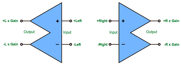
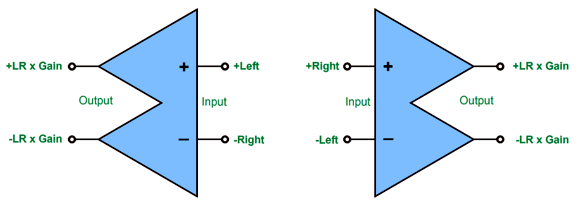
Each channel gets a balanced set of input signals, one non-inverted, one inverted. By the way, the gain might be unity. Now, let's alter this arrangement to create two identical mono signals.
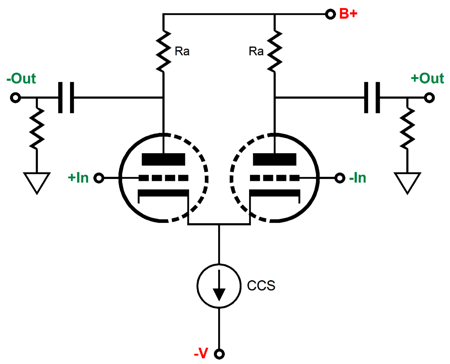
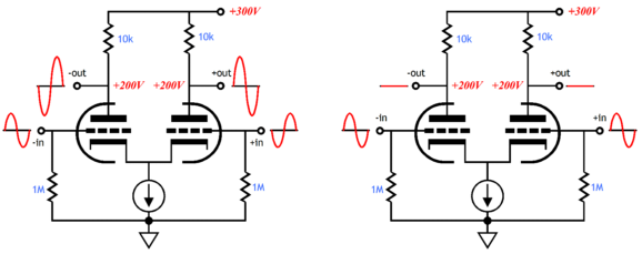
Note the inverting input gets the other channel's inverted signal, which then sums in phase with the non-inverted signal. In order to see how this is possible, here is a super simple differential amplifier based on two triodes.
If we apply signal to only one input, we will still get two anti-phase output signals, which explains why this circuit (aka the long-tail phase splitter) is used a phase splitter in push-pull power amplifiers. Now, let's look at a simple unity-gain balanced line-stage buffer made up of an isolation transformer.
Note that the primary makes no connection to ground, which is as it should be, as this will sidestep many grounding problems. If the balanced signal includes its own output coupling signal transformers, the arrangement to create mono looks like the following:
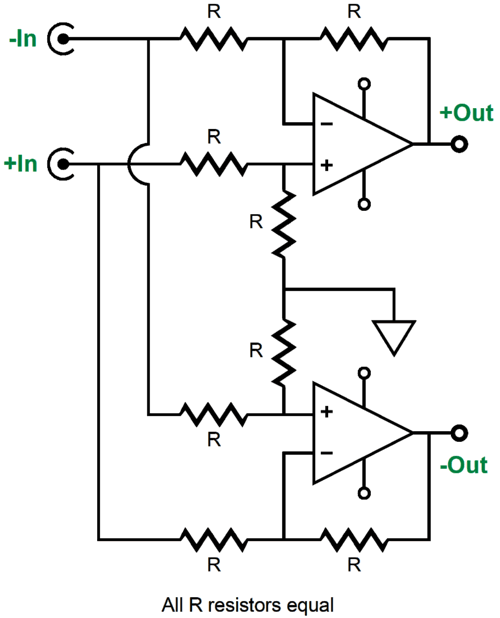
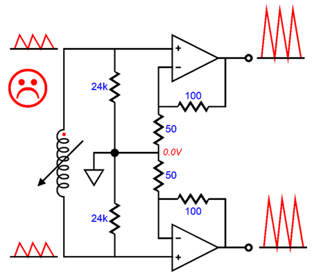
In the center, there's only one current path for the two secondaries and two primaries, so left and right must sum, thereby creating mono. Since high-quality signal transformers are expensive, they are usually replaced by OpAmps and resistors. Here is one channel's unity-gain balanced line-stage amplifier.
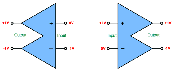
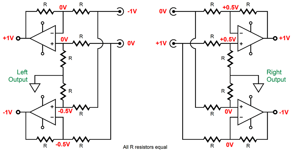
This is a differential amplifier that will not pass at its outputs a signal common to both its inputs. For example, if both inputs see 1Vdc as an input signal, both outputs will deliver 0Vdc at their outputs. Let's now return to the following circuit arrangement, wherein the inverted balanced signals are cross-fed to the other channel's inverted input. Only one channel's signal holds any voltage, in this example, 1Vdc and -1Vdc.
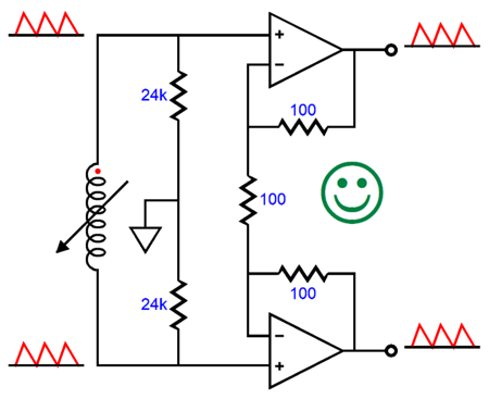
Next, we see how the two OpAmp-based differential amplifiers yield the same result.
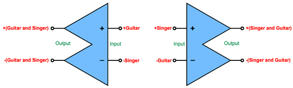
Remember that the way an OpAmp functions is that it strives to maintain the exact same voltage at both its inputs. What works with DC voltages, will also work with music. Imagine a stereo recording of a singer with an accompanying guitarist, such as Tuck and Patty, with the left channel holding the guitar; the right, the singer.
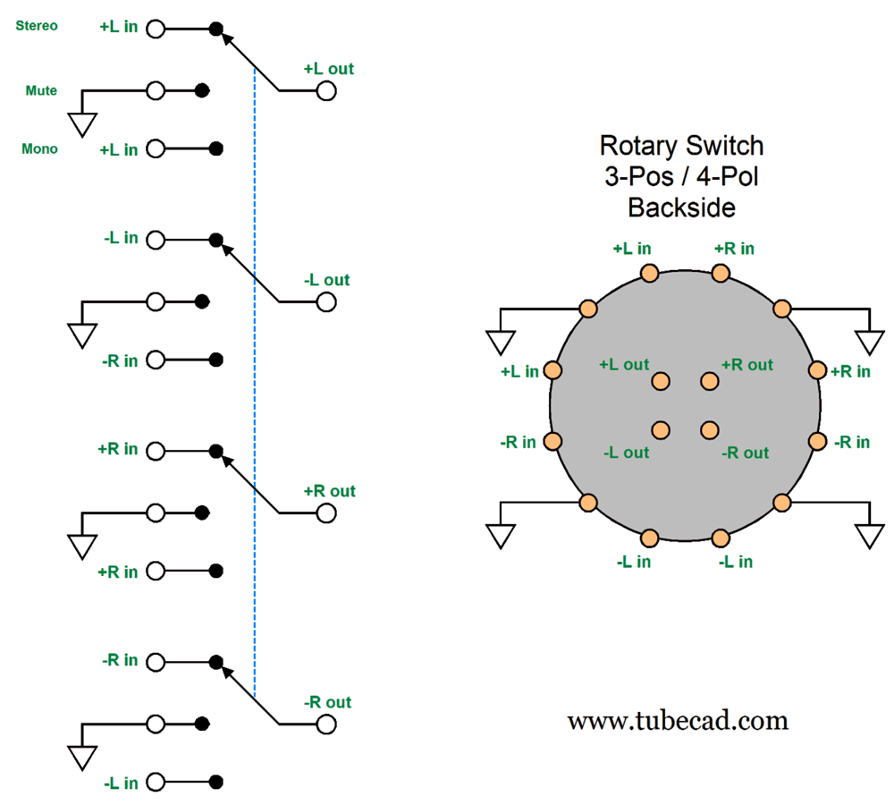
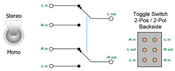
Both channels now hold the same mono signal. To make a Stereo-Mono switch work with this setup, once again, requires only a three-position and four-pole rotary switch.
Only five wires are needed to connect up to the rotary switch: +L, -L, ground, +Resistor, -R. Using a toggle switch is even easier, as the only the inverted inputs need to be switched. Long live mono.
I assumed the rear arrangement of the typical toggle switch, but others might be flipped vertically. The key feature when buying a toggle switch to switch audio signals is that the contact material is hard gold, not silver or brass.
Balanced Phono Preamps
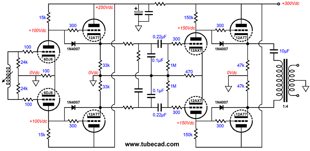
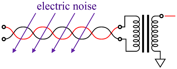
This design might be best, if the use of many tubes were the goal or if the abjuration of solid-state devices was the prime objective. Since this design forgoes the use of solid-state constant-current sources, the output transformer is essential to obtaining a decent common-mode-rejection ratio (CMRR), as without the transformer almost no CMRR occurs. Is that important? Yes, especially as a high CMRR is the defining feature of balanced operation. Why? External noise is usually a common-mode signal.
The transformer's primary is a fundamentally differential contrivance: it only passes differences on to the secondary. Never forget that we live in an environment filled with electromagnetic noise, as our houses are filled with radiating electronic devices and AC motors. Few of us, however, can afford to house our sound systems in a Faraday-cage lined room. Then there's the issue of the miniscule voltage output leaving a phono cartridge, with moving-coil cartridges offering ten times less output than moving-magnet cartridges. Most microphones get a balanced preamp and the same logic applies to phono cartridges. If we replaced the 100-ohm and 470-ohm cathode resistors with constant-current sources, we would get the needed CMRR without the output transformer. The addition of the constant-current source transforms the input stage into a decent differential amplifier that ignores common-mode signals at its inputs.
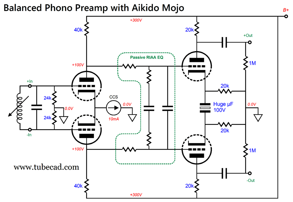
The output transformer served a secondary purpose, however, that of improving the PSRR. The power-supply noise, too, is a common-mode signal that the output transformer's primary ignores. In other words, if we eliminate the output transformer, we must fix two problems, not one. Here is an overview of one possible solution:
The input stage's constant-current source ensures its high CMRR of noise at its inputs, but it also produces a nonexistent PSRR from the input stage. Think about it: if a constant current flows through the two 40k plate resistors, then a constant voltage drop develops across the resistors, which means that all of the power-supply noise appears at the plates. Next, the passive RIAA equalization network is not ground referenced, so still all of the power-supply noise appears at its balanced outputs. The second stage then acts like a long-tail phase splitter to balanced signals, providing gain; but acts like a split-load phase splitter to common-mode signals, thereby creating a power-supply-noise null at the plates.
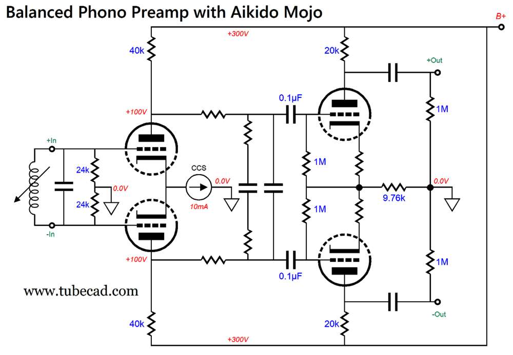
The huge-µF non-polarized electrolytic capacitor that bridges the cathodes is there to absorb the first stage's possible plate-voltage difference. (In SPICE simulations, no such plate-voltage differences are possible, as all SPICE triodes are perfectly matched. Reality differs.) Bear in mind, non-polarized electrolytic capacitor are not the same as polarized electrolytic capacitors, as they can sound quite good. No doubt, some cannot imagine this being true and enjoying paying $$$ for fancy coupling capacitors. For these audiophiles, the following variation forswears non-polarized electrolytic capacitors.
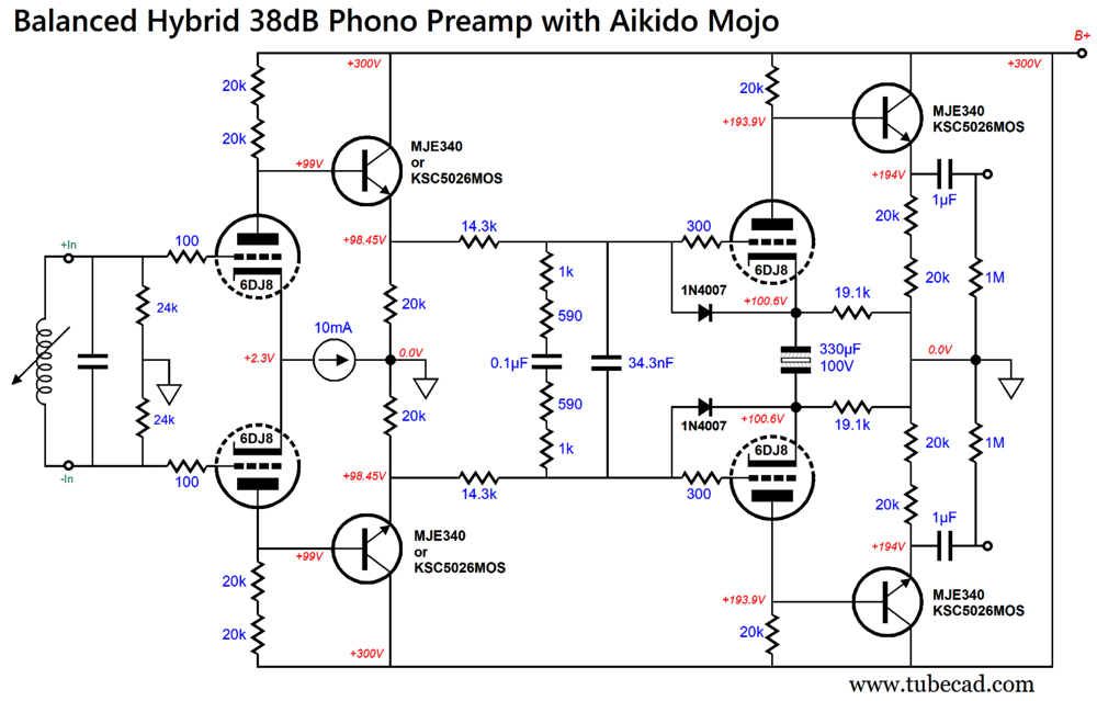
Now that I look at this variation, I see that I could have used one fewer cathode resistor on the second stage, which would not subtract from potential gain. Speaking of gain, note that the 20k plate resistors are effectively in parallel with the line-stage amplifier's volume control potentiometers, which might be as low as 10k in resistance. This partially explains the use of cathode followers in the schematic from post 327. In addition, the passive RIAA equalization assumes a fixed and preferably low output impedance from the input stage, which the cathode followers deliver. What if we replace the cathode followers with emitter followers?
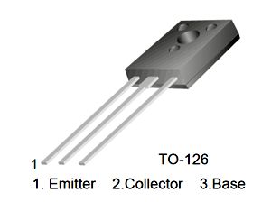
The NPN transistors are 20W high-voltage power transistors in the TO-126 plastic package.
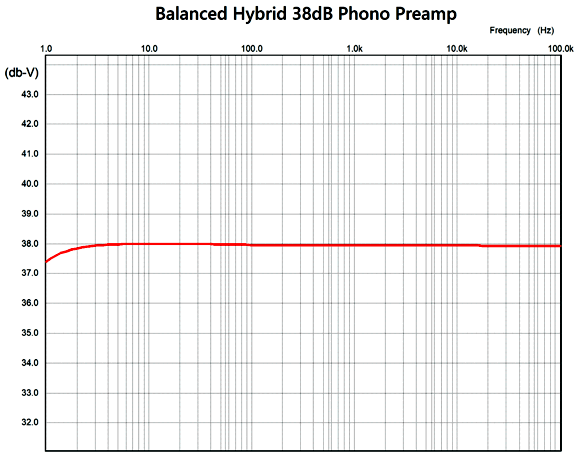
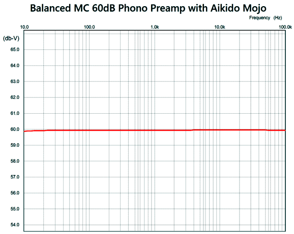
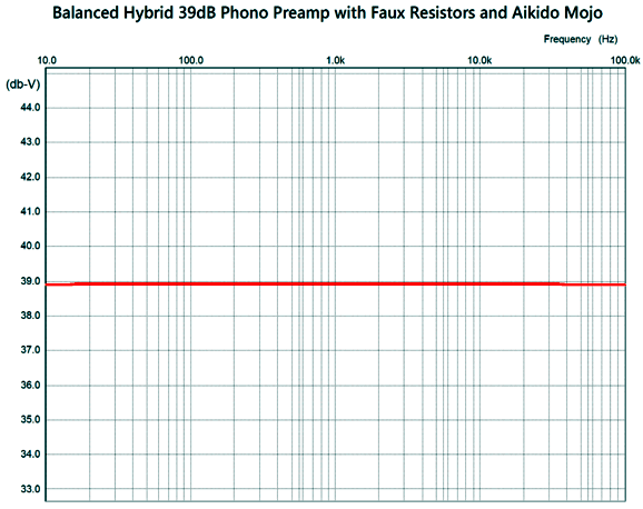
Why not use something beefier in a TO-220 package? We could, but the smaller transistors offer greater high-frequency bandwidth. Another possible choice is the Darlington TTD1409B from Toshiba, whose low input capacitance ensures less high-frequency loss. These transistors do not need big heatsinks, as they dissipate little heat. In SPICE simulations, this balanced phono preamp delivered a dang flat RIAA equalization plotline, being no more than ± 0.06dB from 20Hz to 100kHz.
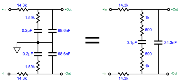
The passive RIAA equalization network is made up from easily obtainable 1% parts, except for the 34.3nF capacitor, which can be made by placing a 1% 30nF capacitor in parallel with a 4.3nF capacitor. By the way, the capacitor values might seem half as big as they should be. Here is what is going on:
Because we are dealing with balanced input signals, the capacitors are effectively in series with each other; thus, 0.2µF in series with 0.2µF equals 0.1µF. By the way, not only do we save on expensive capacitors, but the arrangement on the right allows the Aikido-mojo trick to obtain far better results than the version on the left. Speaking of Aikido mojo, note that the 20k cathode resistors have been replaced by 19.1k resistors. Why? The second stage triodes do not offer infinite transconductance, so a lower-valued cathode resistor is needed to make up for the deficiency. And speaking of deficiency, a gain of +38dB is not a lot of gain. If we need more gain, then tube swapping is not the way to go, as we also need high transconductance and high idle current to develop low-noise gain. Replacing the 6DJ8s with 12AX7s will create more gain, but it will also increase the amount of noise. On the other hand, if we only need a tad bit more gain, say +6dB more, then replacing the second 6DJ8 with a 12AT7 (and replacing the cathode and plate resistors with 47k resistors) will buy us that 6dB increase. To be frank, I quite like the 6DJ8 and 12AT7 pairing, as the differing sonic signatures seem to sum to something more neutral than either tube alone. For those using moving-coil cartridges, something much closer to 60dB is needed from the phono preamp. An MC step-up transformer is the easiest workaround. Sadly, high-quality signal transformers are not cheap. At the risk of turning off pure-tube enthusiasts, the less easy but less inexpensive solution is to use a solid-state built-in pre-preamp. We could use discrete solid-state devices, but that would entail a lot more circuitry. In addition, low-noise OpAmps are being made today, whereas the same cannot be said of the gloriously low-noise FETs that were made by Toshiba forty years ago. Even many low-noise transistors are no longer made. So, OpAmps it is. Here is an example of a balanced pre-preamp that offers the opposite of CMRR, as it actually amplifies common-mode input signals.
The negative feedback resistors set a gain of 1:3 per OpAmp. If we alter the arrangement, we get a pre-preamp that delivers the same gain, but only unity-gain of common-mode input signals.
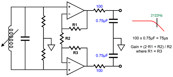
Note that none of the negative feedback resistors terminate into ground. As a result, this example delivers the same gain to the audio signal, but only unity-gain to the common-mode noise. The following balanced differential tube-based stages then have the task of ignoring the common-mode noise, amplifying only the balanced audio signal from the phono cartridge. In addition, to providing more gain, the OpAmps deliver a low output impedance, which can be put to use driving balanced 75µs, 2122Hz low-pass filters. This is part of the RIAA equalization. Placing the 2122Hz low-pass filters early on in the audio chain unloads the following stages from having to amplify high-frequency ticks and pops, but does result in more noise than placing it at the end of the chain.
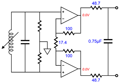
Note that we can forgo the use of two capacitors in the 2122Hz low-pass filters by breaking the connection to ground.
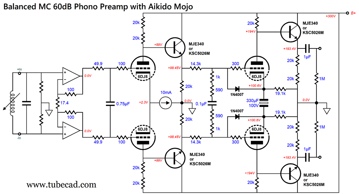
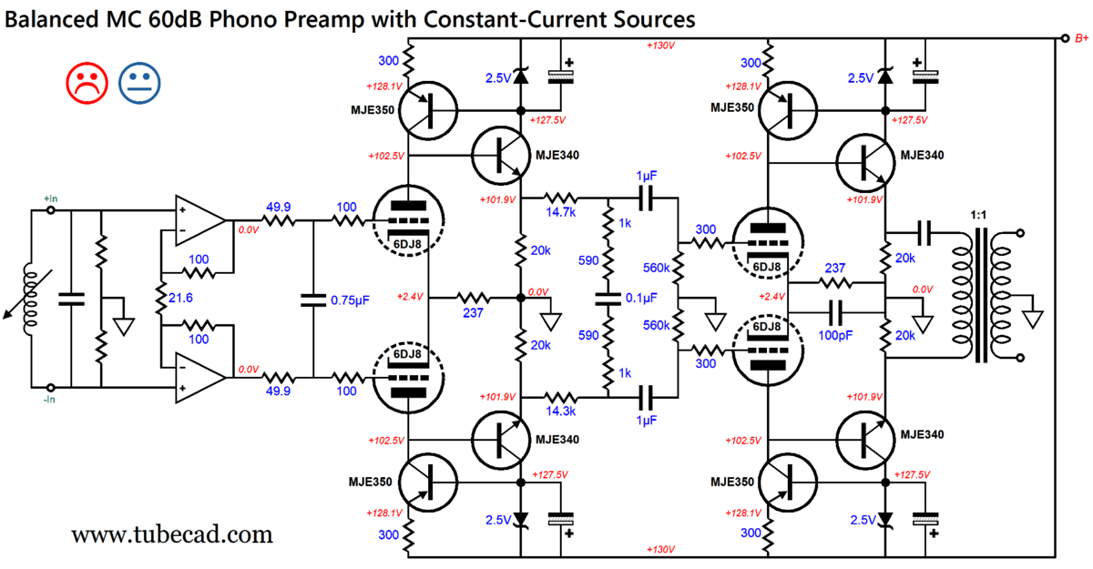
Shouldn't the 48.7-ohm resistors be 50-ohm resistors? The answer is that it depends on the OpAmp output impedance and amount of capacitance in the rest of the circuit. In SPICE simulations, with an assumption of an output impedance of zero ohms, the 48.7-ohm resistors combated some of the input Miller-effect capacitance of the tube-based difference amplifiers. Mileage may vary, in other words. The following is a 60dB MC balanced phono preamp.
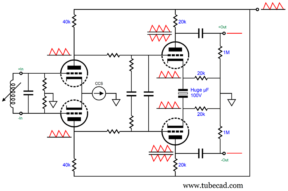
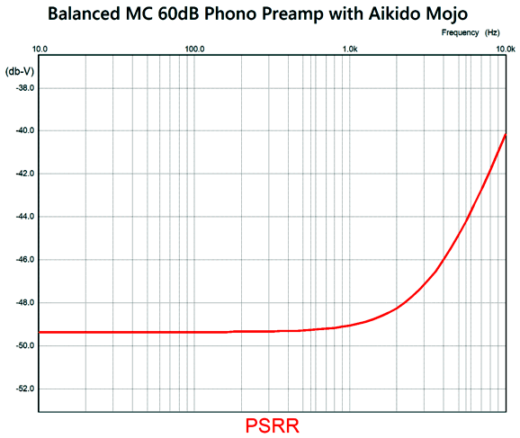
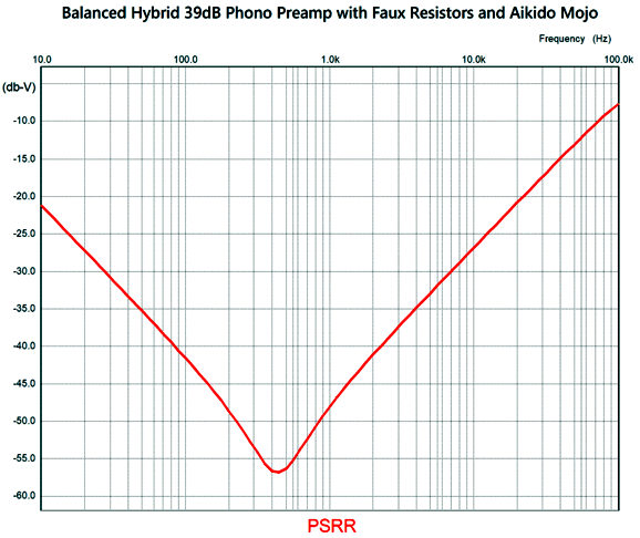
I like the look of this phono stage, as it is tube-frugal and employs some Aikido mojo. The OpAmp-based pre-preamp delivers a gain +22dB, which when combined with the rest of the preamp's gain of 38dB, brings us up to 60dB. If less gain is needed, we replace the 17.4-ohm resistor with a higher value; if more is needed, a lower value. The OpAmps will need a ±12Vdc bipolar power supply, a cleanly regulated power supply. In addition, the B+ voltage must be also regulated. Think of the Aikido mojo as frosting on a cake, and that we should start with a good cake. Speaking of power-supply noise, here is the SPICE-generated graph of this circuit's PSRR.
The frequency plot is marvelously flat.
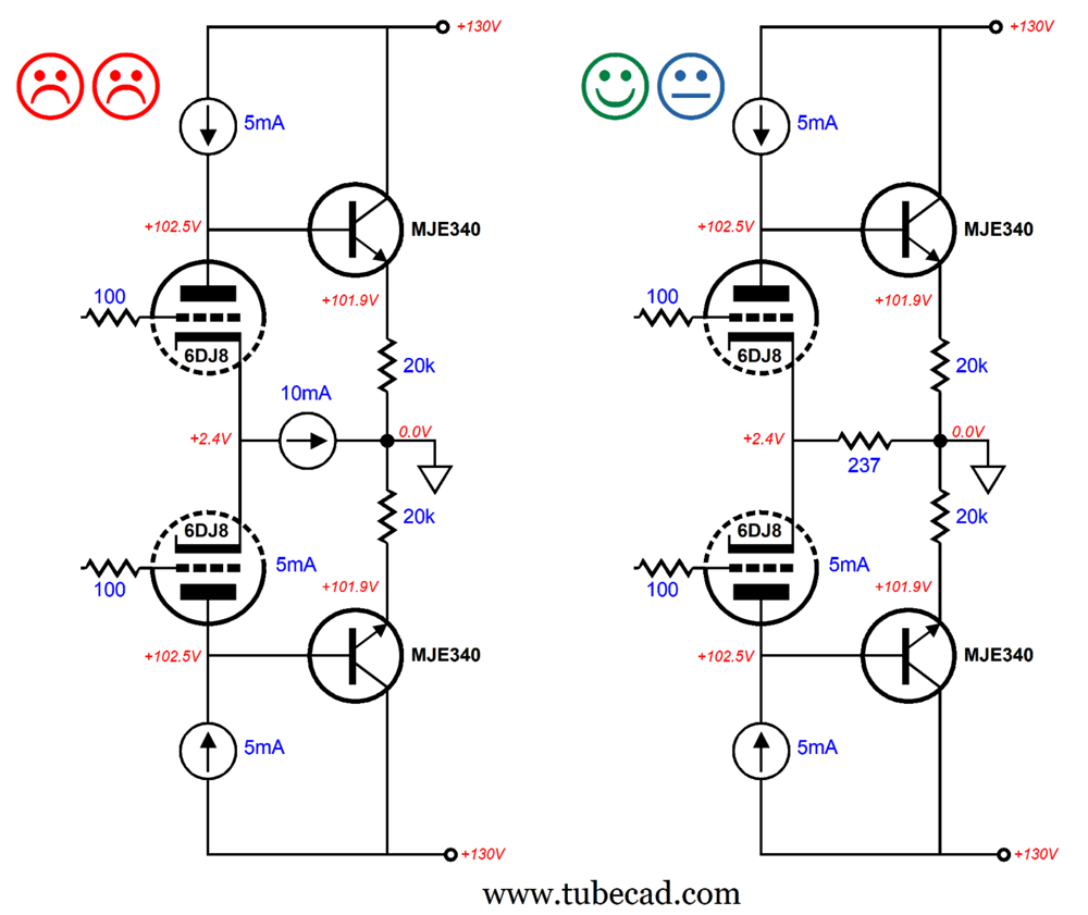
Note that the second 6DJ8 has its cathodes sitting at around +100Vdc, but the first 6DJ8 cathodes are only a few volts above ground potential. We should split the difference, 50Vdc, and reference the regulated heater power supply to that voltage, so each heater-to-cathode voltage is roughly the same (in absolute terms). One thought that troubled me was how to deal with phono cartridges that do not offer floating outputs, as some cartridges ground their coils. In other words, would the balanced phono stage be stymied by this? No. Although we do lose the potential for high CMRR, this phono preamp will still put out a set of balanced signals. Another thought I had was that we could replace the plate resistors with constant-current sources, which would buy us a tad bit more gain and greater PSRR—but, in addition, it also would allow us to reduce the B+ voltage. One problem we would face, however, is that it is never a good idea to place two constant-current sources in series.
The circuit on the left will not work even in SPICE simulations, as one of the triodes will latch-up, while its partner will cease to conduct altogether. The workaround is simply not to place two constant-current sources in series. In the circuit on the right, we see the shared cathode resistor. Since this resistor is so small in value, the CMRR will be nearly nonexistent. Here is one workaround to the lack of CMRR.
The 1:1 isolation signal transformer on the output must perform the rejection of common-mode signals, which would include power-supply noise. In other words, we are back to the nearly decade-old design balanced phono stage from post 327 that started this adventure. Well, the noncommittal face betrays my disfavor with this design. Perhaps if the OpAmps were replaced by a single step-up transformer and the 2122Hz low-pass filter moved between the two tube-based gain stages, I would be more favorably attuned to the design, as that would ensure high CMRR both coming and going. Another possible escape from the trap of two constant-current sources in series is the faux resistor.
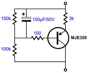
This active load looks something like a constant-current source, but it also looks like a fixed resistance—at least in terms of DC voltages. (By the way, if we remove the 3k emitter resistor and 100µF capacitor, the circuit becomes something like a faux zener.) Next, we see the SPICE simulation DC-transfer graph that sweeps the voltage across the circuit from 0V to 10Vdc.
Note that with a wee more than 1Vdc, the plotline resembles that of a resistor. (In fact, a resistor in series with a silicon diode will create the same plotline.) The formula for determining resistance from such a current plot is Resistance = Voltage / Current. In other words, if we measure the slope, we will know the resistance at that portion of the plotline. If we perform the math with this plotline, centering our sampling at 5Vdc we get around 6368 ohms. Let's now increase the sweep out to 100Vdc.
If we perform the math with this plotline, but centering sampling at 30Vdc we get around 5414 ohms. What's going on here? Below about 10 volts, the plotline betrays some curvature, which the eye strains to see; but above 20Vdc, the line straightens substantially. With the voltage drop of 30V, the current flow equals about 5mA, which seems to imply a DC resistance of 6k. Interestingly enough, DC resistance is not what we should be looking at, but impedance. In terms of AC, the impedance from 10Hz to 100kHz is around 87.5k, hence the name of faux resistor. Bear in mind that the 100µF capacitor forms an RC filter, with the 100k in parallel with the 150k resistor. In other words, this capacitor defines a near AC dead short to audio signals. The 100k is also in parallel with the PNP transistor's collector impedance (about 700k due to the Early effect). In addition, the triode's plate is loaded by the NPN transistor's input impedance. The 100-ohm resistor serves as a base-stopper resistor that prevents high-frequency oscillations. Let's use the lower B+ voltage and the faux resistors in place of the old plate resistors.
The low 130Vdc B+ voltage is a nice treat, as each channel draws 40mA of current, which against 130V equals 5.2W of dissipation. In contrast, with a B+ voltage of 300Vdc, the dissipation would be 12W per channel. In addition, a 120Vac secondary rectifies up to about 165Vdc, which would give us enough voltage headroom to allow solid-state voltage regulation of the B+ voltage. All in all, this is the balanced phono stage I would build. If more gain were needed the step-up input transformer or the OpAmp solution could be added. The THD was crazy low in SPICE simulations as well. Too low to quote, let alone believe. The differential input stage supplies the desired CMRR and delivers some CMRR; more importantly, it is infused with Aikido mojo. The 36.5k resistor shunting the constant-current source forces a greater than -40dB power-supply noise null at the 100Hz.
Without the Aikido-mojo resistor, the PSRR was a dismal 0.34dB. The RIAA equalization plot is the flattest that I have ever seen in a SPICE simulation of a phono stage.
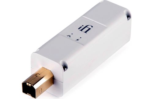
More Digital Domestication The SACD arrived and it sounded better, but still failed to live up to its potential. Then higher sampling frequencies and deeper bit depth, yet the disappointment remained. Decades pass, and the convenience of digital-music storage on hard-drives and the abundance of streamed music, much of it in high-res, compelled my near complete surrender to ones and zeros. Today, with re-clocking and de-jittering, I willingly and joyfully submit to ones and zeros, as my music universe has expanded hugely. Mere 16-bit, 44.1kHz recordings now sound stunning. Old albums, which I liked but couldn't bear to hear, are now quite listenable in their digital carnation, if not quaffable. Let's be frank: The whole—and only moral—justification for high-end audio is greater music appreciation. Anything else is fundamentally and irredeemably philistine. I recently bought an iPurifier3 that, like the iPurifier2 I already owned, employs active noise cancellation, re-clocking, and jitter reduction—but this time with digital asynchronous streams that connect through USB terminals, not SPDIF coaxial or fiber optic cable. I needed it for use with my laptop when away from my stereo system and listening to headphones and unable or unwilling to hook-up one of my many tube-based headphone amplifiers; I use my Pro-Ject DAC Pre Box S2 run off a battery, as the unit holds a decent-sounding headphone amplifier. Here is an email I sent to my friend, Glenn:
I also used the iPurifier3, Oyaide Class S USB cable, and my laptop to drive my Schiit Gungnir revision-B multibit DAC, which in turn fed my dual-cathode-follower unity-gain line-stage amplifier and then single-ended amplifiers. Amazing sound. I found myself liking albums that I didn't previously like. A California audiophile, who happens to be my son's godfather and who had recently visited us in Colorado, heard what the Mutec M3+ succeeded in producing in the digital chain and, in the hope of capturing some of that magic, bought an iPurifier3. Here is what he wrote as a response:
I agree, especially with his last observation. My attention now locks onto the vocals, not the instruments, as the vocals now sound real, whereas they had sounded somewhat flattened and canned. Yet, there's no alteration in frequency response or increase in volume. (Your system will sound much quieter—even if it was noise free before.) One analogy that comes to mind is that of a swimming pool with an elaborate and arresting tile bottom that you have not been able to make out clearly as the water splashes about too much due to the play of children; with the pool empty of swimmers, you now see the mosaic portrayal of a mermaid.
The amazing thing is that just a $150 iPurifier3 or $200 iPurifier2 or the $1,200 Mutec M3+ can improve the sound out of truly expensive DACs. For example, some of our listening tests were done with the Mola Mola Tambaqui ($13,500) and the T + A DAC 200 ($7,620). What isn't clear is how this is possible? Fancy DACs do their own re-clocking and de-jittering internally. From the Mola Mola website:
In addition, the Mola Mola DAC rejects jitter by -80dB, which translates to by 10,000 fold. That's a lot. The old problem with asynchronous data transfer was under-fill or overfill, as RAM was expensive. Today it isn't. Once again, how can an external re-clocker, de-jitter, active noise filter improve upon the DAC's internal equivalent circuitry? My guess is that noise on either the SPDIF or USB cables creates headaches for the DAC, which leads to the following bit of advice. One caveat worth pointing out is that, with re-clocking and de-jittering, digital cables become more important. Why? Probably for the same reason that when you clean your windows, you can see more clearly both more beautiful flowers and more weeds in your garden. In other words, as your system increases in resolution, the greater the differences become between digital cables. A few months ago, I only heard small differences; now, huge differences. My friends and I recently held shootouts with many different USB cables, with one costing $700. The most expensive cable didn't win. All the USB cables from Oyaide delivered the most bangs per buck, which relative to the expensive alternatives proved to be a bargain. Terminating long cheap USB cable with short expensive USB cable does not sound as good as the short expensive USB cable alone. Interestingly enough, using the short expensive USB cable first, then the iPurifier3, and then the long cheap USB cable sounded better than the alternative long cheap USB cable then short expensive USB and then iPurifier3 terminating into the DAC.
Music Recommendation: Bria Skonberg's Bria
Prior to re-clocking and de-jittering my digital playback, I listened to this album twice, never was I thrilled. (And I quite like Bria's singing and horn blowing.) Today, I am thrilled. The reduction in noise and increase in clarity allows this album's virtues to shine forth. A good example is the purely instrumental track, "Egyptian Fantasy," which reveals excellent imaging and transparency—besides, this jaunty retro performance is as fun to hear, as it must have been to perform. Her most recent album, What It Means, came out this July. I only discovered it today, so I have only heard a few tracks. Sounds like an excellent album. Her voice seems to have taken on a more mature tone, which better suits jazz vocals.
Both Amazon Music and Qobuz offer these albums in 24-bit, 96kHz. //JRB
Did you enjoy my post? Do you want to see me make it to post 1,000? If so, think about supporting me at Patreon.
User Guides for GlassWare Software
For those of you who still have old computers running Windows XP (32-bit) or any other Windows 32-bit OS, I have setup the download availability of my old old standards: Tube CAD, SE Amp CAD, and Audio Gadgets. The downloads are at the GlassWare-Yahoo store and the price is only $9.95 for each program. http://glass-ware.stores.yahoo.net/adsoffromgla.html So many have asked that I had to do it. WARNING: THESE THREE PROGRAMS WILL NOT RUN UNDER VISTA 64-Bit or WINDOWS 7, 8, and 10 if the OS is not 32-bit or if it is a 64-bit OS. I do plan on remaking all of these programs into 64-bit versions, but it will be a huge ordeal, as programming requires vast chunks of noise-free time, something very rare with children running about. Ideally, I would love to come out with versions that run on iPads and Android-OS tablets.
|
I know that some readers wish to avoid Patreon, so here is a PayPal button instead. Thanks.
John Broskie
John Gives
Special Thanks to the Special 92 To all my patrons, all 92 of them, thank you all again. I want to especially thank
I am truly stunned and appreciative of their support. In addition I want to thank the following patrons:
All of your support makes a big difference. I would love to arrive at the point where creating my posts was my top priority of the day, not something that I have to steal time from other obligations to do. The more support I get, the higher up these posts move up in deserving attention.
If you have been reading my posts, you know that my lifetime goal is reaching post number one thousand. I have 393 more to go. My second goal was to gather 1,000 patrons. Well, that no longer seems possible to me, so I will shoot for a mighty 100 instead. Thus, I have just 8 patrons to go. Help me get there. Thanks.
|
|||


| www.tubecad.com Copyright © 1999-2024 GlassWare All Rights Reserved |