| John Broskie's Guide to Tube Circuit Analysis & Design |
December 18 2024 Post Number 612
High-Quality Subwoofers This simple taxonomy is based on the observation that some subwoofers better suit music playback; others, movie watching. The former deliver the missing low-frequencies in an accurate, natural manner, thereby making home music reproduction closer to that of live attendance in the concert hall or jazz nightclub; the latter produce table shaking thuds and booms, making gunfights, car crashes, and explosions more thrilling. As far as I am concerned, however, subwoofers further divide into blurred and sharp focused, which some label as slow versus fast. Audiophiles, naturally enough, desire sharp-fast HiFi subwoofers. Sadly, physical existence works against us, as low-frequency reproduction requires big, heavy woofers in big heavy enclosures, be they sealed or ported, transmission-lined or horn-loaded. Alas, big and heavy are not attributes we associate with sharp and fast. In addition, the larger the speaker enclosure, the greater the surface area; the greater the surface area, the greater the potential for sound emission. Obviously, the speaker enclosure's surface area dwarfs that of the woofer, being at the very least five times greater in a rectangular box. Those large flat sides do not have to flex much to produce a lot of sound. One workaround is to build hexagonal or octagonal subwoofer enclosures. Ideally, a spherical or a cylindrical enclosure would work best, as these shapes are intrinsically stiffer. Think about how stiff an egg shell is. In fact, I once knew an enterprising audiophile who built his subwoofers using concrete sewer pipes. Imagine an 18-inch pipe four-feet long, each end capped with a 15-inch subwoofer driver. Speaking of pipes, see my post 465 to see my idea of using two metal pipes to create a transmission-line subwoofer. (Sadly, any departure from a rectangular box makes both construction and user acceptance tough.) In addition, that post holds a section devoted to using a subwoofer with headphones, which I do all the time. (Look up the definition of the word "somatosensation.")
Decades ago, my workaround to the flexing-sides problem was to take a cube subwoofer enclosure and line five of its inner surfaces with 1/4th-inch thick industrial felt, to which I glued square sheet glass (which received a second layer of felt on its other side). Why? I had once taken a deep dive into how low-frequency sound proofing could be incorporated into a condominium's design. At the library, a book showed the varying amount of attenuation of low-frequencies for many different building materials, such as sheetrock, plywood, pressboard, concrete, glass, metal… It was a depressing graph to behold, as four-inch thick concrete slabs were amazingly acoustically transparent at 20Hz. (If I remember correctly, even more transparent than sheetrock and double stud walls. In that same book, I noted that laminated glass performed better than single-layer glass panes at sound attenuation. My hope was that the plywood-felt-glass sandwich might supercharge the lamination effect, where the trapped quarter-inch felt layer would transform the acoustic energy into heat. It did. Although it made for a heavy enclosure, it worked far better than thicker wood sides. (I had previously built subwoofer enclosures with 2.5-inch walls.) Light and stiff are the desirable attributes we seek, with glass panes being the most readily available inner panels that I could think of. On the other hand, sheets of laminated aluminum used in airplane construction might work better, as might ceramic tiles. Ideally, sheets of industrial diamond would prove best—and due to the high cost, all the more desirable in audiophile terms. In addition, I did not stuff the enclosure with polyfill. Why not? In a sealed loudspeaker enclosure, the trapped air acts like a capacitor. When we fill it with stuffing, we effectively create a capacitor with high dielectric absorption (DA), which creates soggy bass reproduction. In a transmission-line subwoofer, however, the stuffing is an asset.
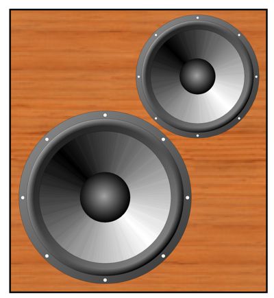
Next, we move on to the subwoofer drivers. In order to achieve a low free-air resonance, the woofer diaphragm must be massive and hold a loose surround. We can't expect these woofers to move quickly. Thus, I have long wished to build a two-way subwoofer that held both a big, slow woofer and a small, fast woofer. With a low-frequency cutoff frequency of 30Hz, we might impose a 60Hz crossover frequency. Ideally, 1st-order slopes would be used to ensure a flat-phase response between woofers. Imagine a 2- or 4-ohm, 15-inch woofer with an 8-ohm, 10-inch woofer in an internally bi-amped setup, with active filters. Both drivers should share the same in-cabinet frequency (Fc) and the same steep low-pass filter at 80Hz to 160Hz. What about the Qs? A loudspeaker's Q is short for "Quality Factor" and is a unit-less number that describes a negative attribute in positive terms, as it refers to how damped a loudspeaker driver is at resonance, with a low Q meaning well damped and a high Q meaning not much damped. Loudspeaker Q comes in four flavors, the first three of which apply to the speaker driver outside an enclosure: mechanical Q (Qms), electrical Q (Qes), and the combined mechanical and electrical Q's (Qts); and the driver's Q in an enclosure (Qtc). Tuning forks are meant to resonate loudly and continuously, thus they exhibit a crazy high Q, as in 1000. In contrast, critically damped resonances have a Q of 0.5. Few loudspeakers sport this Q, as it results in a -6dB dip in SPL at resonance. A booming and party-pleasing loudspeaker might have a Q of 1.2 or higher. Typically, a Q of 0.7 is often considered a good target Q for a loudspeaker, neither an introvert nor an extrovert (i.e. an ambivert, which most people are, by the way). By using an active crossover and internal power amplifiers, however, we have many more options available to us. For example, the 15-inch woofer might exhibit a Qtc of 1.1, while the 10-inch woofer's Qtc is a low 0.5. If we add a 2nd-order high-pass filter to the mix, a filter tuned to the speaker Fc frequency in a closed box, so that the subwoofer drivers are not required to reproduce turntable rumble or, God forbid, DC cone movement, we can easily tune the 2nd-order filter's Q. We would duplicate the 2nd-order high-pass filters, at the loudspeaker's resonant frequency, giving the bigger woofer's filter a Q of 0.636 and giving the smaller woofer's filter a Q of 1.4, which would effectively yield a Q of 0.7 from both drivers. (Cascading Qs are multiplied together.) Hell, it would be fun to build a three-way subwoofer that gave the biggest woofer only the first octave of 20Hz to 40Hz to handle, the middle-sized driver the second octave of 40Hz to 80Hz, while the smallest driver handled the last octave of 80Hz to 160Hz (and beyond). Does this make any sense with a low-pass filter frequency of 80Hz or 100Hz? I believe it does, as this three-way subwoofer would simply behave as if it were an amazingly wide bandwidth fullrange, capable of going down to 20Hz at high SPL, while still able to deliver crisp 3kHz tones.
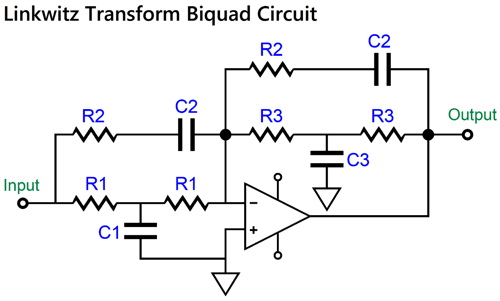
(Such a subwoofer would make an excellent speaker stand, especially of it held a downward sloping front, so as to time align the three voicecoils.) Since it is highly unlikely that the smaller driver (say a 7-inch woofer) could exhibit an in-box resonant frequency of 20Hz, we would use a clever circuit, the "Linkwitz Transform" biquad, that the late Siegfried Linkwitz created to electronically alter a driver's Ftc and Qtc in a sealed enclosure.
In fact, this circuit would probably be needed for the middle-sized driver, as even a 10-inch woofer would have a hard time delivering an Ftc of 20Hz. Bear in mind, that this circuit lowers the apparent resonance by applying a bass boost. In other words, the 1st-order crossover slopes might actually become upward slopes at the lowest frequencies; this depends on how much higher up in frequency the driver's natural in-box resonance is relative to the low-frequency cutoff. Remember that this small driver, however, also sees two 1st-order high-pass filters in series, 40Hz and 80Hz. Nonetheless, the importance of adding an in-series 2nd-order high-pass filter at 20Hz becomes even more important with the potential of any bass boosting.
As I pondered just how fine such a subwoofer might sound, I thought it a pity that all three woofers would be engaged, even when the lowest frequency reproduced wasn't all that low or when the SPL wasn't all that high, as the smallest driver would prove the most articulate. In a flash, an entirely different approach hit me.
Amplitude-Staggered Subwoofers
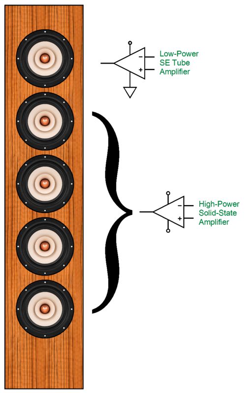
So far, this doesn't sound promising, as the big driver is slow and the small driver is limited in excursion. (We assume the use of a HiFi woofer as the smaller driver, not a woofer designed for subwoofer use.) The audio alchemy is found in that only the small driver delivers bass when the sound volume is low or the music is bass shy. When either the volume soars up and-or the bass thunders, the big driver engages, while the small driver flat-lines, their combined output summing to the intended output. In short, output level staggered woofers. Such an arrangement would prove a fine miracle, but how do we achieve it? I am lucky in that I already had created the solution. Almost exactly one decade ago in Post 280, I had turned my Sauron-like eye upon the Bose 901 loudspeaker system, where I displayed many alternative arrangements, including a two-amplifier setup, wherein the single front-firing speaker driver was lucky enough to be powered by a fine single-ended tube-based amplifier, while the rear-firing drivers were saddled with a solid-state (class-D) amplifier. One alternative arrangement that I devised also held two power amplifiers, but held five front-firing fullrange drivers, only one of which played at low SPLs, the others coming in at high SPLs. I didn't include this idea in that post, as I deemed the idea worth its own post. Then, I pretty much forgot about it. (A lot of audio travels under my mental bridge.)
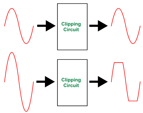
The plan is to feed the audio signal into a clipping circuit and then to feed the clipping circuit's output into both the power amplifier that drives the single fullrange driver and into a differential circuit that also sees and compares this signal to the un-clipped signal. If the signal is low enough to escape being clipped, then the differential circuit's output is zero, as there's no difference between the input signal and the clipper circuit's output. Thus, only the single fullrange driver gets powered at low volume. When the clipper circuit's output exhibits clipping, the differential circuit sees that difference and delivers it as the output signal for the bigger solid-state power amplifier that drives the four fullrange drivers. Think of it as an audio automatic transmission—or, better still, an audio turbocharger.
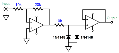
Much like a power amplifier that clips, the clipping circuit readily passes signals whose amplitude fall within its power supply's throughput window of plus and minus voltages. It differs from a clipping power amplifier in that the clipping is clean and the clipping circuit does exhibit power amplifier problems, such as blown fuses, oscillations, and output latch-up. Building a precise clipping circuit is easy enough:
The OpAmp on the left is a simple inverting amplifier with a gain of 1:-2. Assuming an input signal of 1Vpk, this amplifier stage will put out 2Vpk. The 10k resistor and two signal diodes (1N4148) perform the clipping function, engaging at about ± 0.55Vpk. Next, we move on to the differential amplifier
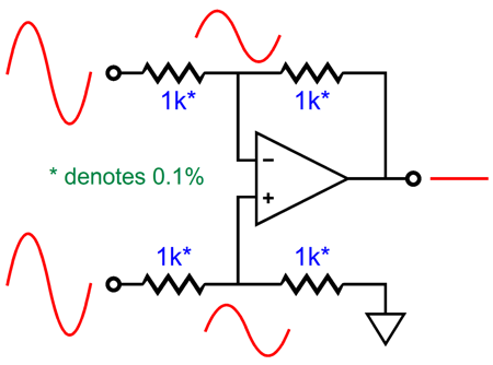
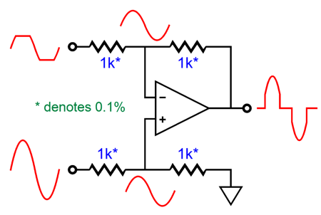
The differential amplifier only passes differences. Since the two input signals are identical in the above example, the differential amplifier's output is zero. On the other hand, if we feed the differential amplifier dissimilar signals, its output will reveal the difference between the two signals.
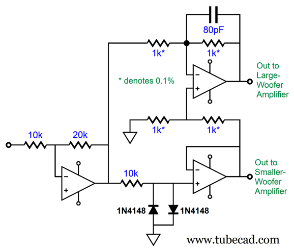
This is the signal that we will feed the power amplifier that drives the bigger woofer, while the clipped signal is what feeds the power amplifier that drives the smaller woofer. In the air, the two woofer outputs combine to create and undistorted waveform. Let's add the clipper circuit to the differential amplifier.
Note that the output for the large woofer is not-inverted, while the output to the smaller woofer is inverted. In addition, missing is the high-pass and low-pass filters. Let's add them and the "Linkwitz Transform" biquad circuit.
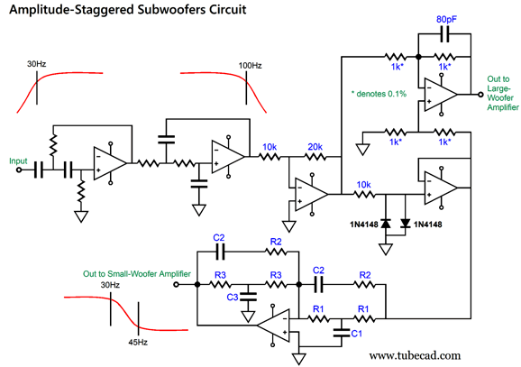
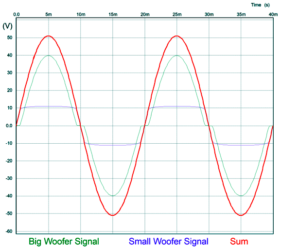
Now, both woofers see a non-inverted signal, as the Linkwitz Ftc shifting circuit inverts its input signal at its output. The two frequencies it deals with are a design example only. Note the use of 0.1% resistors in the differential amplifier, which are needed to ensure balanced voltage division between the two input signals. Also note the 80pF capacitor that shunts one of the 0.1% resistors. It is needed to balance the capacitance presented by the two 1N4148 signal diodes. The inverting amplifier that feeds both the differential amplifier and the clipping circuit delivers a gain of 6dB (i.e. 1:-2), which means that a 1Vpk input signal leaves its output at 2Vpk. My assumption here is that the two internal power amplifiers deliver a gain of 26dB or 1:20, so 2Vpk becomes 40Vpk, which equals 400W with a 2-ohm woofer and 100W with and 8-ohm woofer. If we divide 2V by 0.55V, we get the ratio between the big woofers signal versus the small woofer's, 3.64 to 1. Or, put in percentages, the smaller woofer sees 27.5% of the 4Vpk. In other words, with the big woofer getting 40Vpk, the small woofer tops out at 11Vpk, which equals 7.5W into an 8-ohm woofer. Will that be enough? You would be surprised by how little wattage is needed at low volumes, even with inefficient loudspeakers. On the other hand, if you love organ music or rock-concert SPLs, the big woofer will be constantly in use. We can alter the ratio between the two drivers either by using a more powerful power amplifier to drive the large woofer or by adding additional diodes in series (which would necessitate using a 40pF capacitor rather than the 80pF). The first alternative gives the big woofer a larger share of the output, while the second gives the smaller woofer more to handle. Or, we could play with the inverting amplifier's gain to alter the ratio. As always, experimentation is needed. Until we can summon the effort and money to deal with reality, we have SPICE. The following graph shows the SPICE simulation of the clipper circuit, differential amplifier, and two power amplifiers, each with a gain of 26dB (1:20).
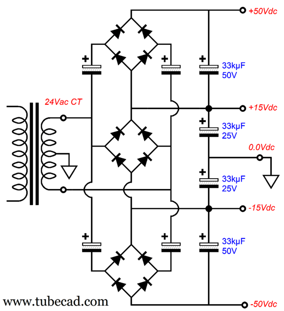
The "Sum" occurs in the air. Note the big-woofer's input signal flat-lines near the zero crossing, while the small woofer's signal more closely resembles a square-wave. Square-waves produce more heat than sinewaves. The 11Vpk, which with a sinewave equals 7.5W into an 8-ohm woofer, equals 15W with a square-wave. (In other words, the square-wave power calculation is the same as the DC calculation.) We must bear this in mind, if we wish to increase the small woofer's share of the output. I assume a bipolar power supply with dual plus-and-minus output voltages; for example, +50V, +15V, 0V, -15V, -50V. The power amplifier that drives the small woofer attaches to the ±15Vdc power-supply rails, while the power amplifier that drives the big woofer attaches to the ±50Vdc power-supply rails. Assuming that the big woofer, a proper subwoofer, holds a 2-ohm voicecoil, these power-supply rail voltages should easily produce up to 400W of power into the 2-ohm load impedance. The OpAmps are powered by the ±15Vdc power-supply rails. We could either use a multi-tap secondary on the power transformer or two power transformers or the following power-supply circuit.
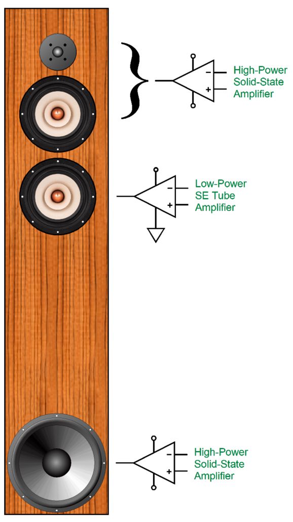
As long as quality music is being played at a reasonable SPL level, this power supply would probably work perfectly. If the subwoofer, however, were used in a disco or as the subwoofer for an electronic organ, the two transformer arrangement would be my first choice. Before I sign off of this topic, let's return to my decade-old idea of the five-fullrange-driver loudspeaker that staggered its drivers based on signal amplitude. Five high-quality fullrange drivers cost a bundle. On the other hand, adding a good woofer and dome tweeter to a fullrange driver is far more reasonably priced.
At moderate volume levels, only the fullrange driver in the center plays. When a threshold signal is reached, the tube-based, single-ended power amplifier that drives this fullrange driver flat-lines, and the secondary three-way speaker system, made up of the tweeter and secondary fullrange and woofer, gets powered. The secondary three-way loudspeaker system must use only 1st-order crossover slopes, with wide crossover frequencies, say at 250Hz and 5kHz, the fullrange driver thereby effectively becoming a midrange driver. I would use a series three-way passive crossover with a tweeter cascade of slopes. (Placing the woofer at the bottom gives it a +6dB boost, which is needed due to the higher efficiency of the fullrange driver.)
Such a loudspeaker would be analogous to serving premium booze at the beginning of the party and then switching to cheap stuff as the partygoers get drunk.
Music Recommendation:The Poems of T.S. Eliot, read by Jeremy Irons Okay, poetry doesn't count as music—but when read by a great Brit actor, it comes close. I recently subscribed to Audible, so I went hunting for some of my favorites. I had some misses and some hits. One big hit was discovering Jeremy Irons reading T.S. Eliot's poetry. I grew up listening to Iron's fellow Brit, Robert Speaight, read Eliot's poetry on LP from Decca's Argo label (1954), which is definitely worth seeking out. (Apple Music offers it, by the way.) Speaight's reading of Eliot's Four Quartets is definitive, in my view. By the way, T.S. Eliot's Ph.D. was in philosophy (Harvard University, 1916), which is evident in Eliot's Four Quartets poems. In fact, I believe that we should add Eliot to the list of great philosophers on the subject of time, such as Pythagoras, Plato, Aristotle, Saint Augustine, Immanuel Kant, David Hume, Henri Bergson, J.M.E. McTaggart, Albert Einstein, Kamala Harris... While I am happy to get any recording of Eliot's poetry and while I greatly admire Irons the actor, he does sound old—which works perfectly for many of the poems, but not all of them, alas. For example, I like hearing the reading of The Lovesong of J. Alfred Prufrock starting out young, then transitioning to old at the end. Irons does, however, bestow the gift of reading aloud poems that I have never heard uttered, save in my mind, such as Mr. Eliot’s Sunday Morning Service. For a mere $16.16, Amazon sells the 4-CD album. (A total playing time of almost four hours.) Here is the list of the poems included:
//JRB
Did you enjoy my post? Do you want to see me make it to post 1,000? If so, think about supporting me at Patreon.
User Guides for GlassWare Software
For those of you who still have old computers running Windows XP (32-bit) or any other Windows 32-bit OS, I have setup the download availability of my old old standards: Tube CAD, SE Amp CAD, and Audio Gadgets. The downloads are at the GlassWare-Yahoo store and the price is only $9.95 for each program. So many have asked that I had to do it. WARNING: THESE THREE PROGRAMS WILL NOT RUN UNDER VISTA 64-Bit or WINDOWS 7, 8, and 10 if the OS is not 32-bit or if it is a 64-bit OS. I do plan on remaking all of these programs into 64-bit versions, but it will be a huge ordeal, as programming requires vast chunks of noise-free time, something very rare with children running about. Ideally, I would love to come out with versions that run on iPads and Android-OS tablets.
|
I know that some readers wish to avoid Patreon, so here is a PayPal button instead. Thanks.
John Broskie
John Gives
Special Thanks to the Special 89 To all my patrons, all 89 of them, thank you all again. I want to especially thank
I am truly stunned and appreciative of their support. In addition I want to thank the following patrons:
All of your support makes a big difference. I would love to arrive at the point where creating my posts was my top priority of the day, not something that I have to steal time from other obligations to do. The more support I get, the higher up these posts move up in deserving attention. If you have been reading my posts, you know that my lifetime goal is reaching post number one thousand. I have 393 more to go. My second goal was to gather 1,000 patrons. Well, that no longer seems possible to me, so I will shoot for a mighty 100 instead. Thus, I have just 8 patrons to go. Help me get there. Thanks.
New URL of the GlassWare website |
|||
| www.tubecad.com Copyright © 1999-2024 GlassWare All Rights Reserved |
