| John Broskie's Guide to Tube Circuit Analysis & Design |
| July 03 2025 | Post Number 623 |
||||||||||||||||||||||||||||||||||
Happy 4th of July!
Accurate Crossovers I caught myself. I was about to make a categorical statement, a statement that was wrong; fortunately, counter examples quickly filled my mind, such as the famous Bose 901 loudspeaker. What I almost wrote was that if a loudspeaker held more than one speaker driver, then it must also hold a passive crossover. Not so. The 901 holds nine identical fullrange drivers, but no crossover. True, it does come with an active equalization box, but the box's circuitry only tailors the frequency response, but does not perform any frequency division, as the nine fullrange drivers all see the same signal. Other counter examples include some public address loudspeakers that hold four or more identical drivers in a linear array wherein all see the same frequency bandwidth. A safer statement is that most loudspeakers that hold more than one driver also hold a passive crossover, which can be as little as just one capacitor to limit the bass frequencies going to the high-frequency driver. Another safe observation is that, in general, the more expensive the loudspeaker, the more elaborate the passive crossover inside. Crossovers slice the audio bandwidth, the famous frequency span of 20Hz to 20kHz, into sections, creating limited bands of frequencies that frequency-selectively portion out the signal from the power amplifier. At its simplest, a two-way crossover steers the high-frequency output to a tweeter, while the sending the low-frequency content to a woofer. Ideally, the transition proves a seamless as expensive nylons or polished marble or as the Chinese saying goes, "Seamless as a Heavenly Garment," without breaks, flowing smoothly from one driver to another, a continuous run of frequencies, so marked by the absence of gaps or interruptions that the dissimilar drivers sound like the unbroken output from a single driver. For most audiophiles, that is what an accurate crossover aims for, but is it enough? Put simply, no.
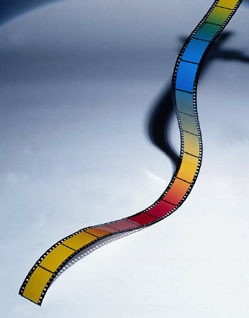
Just as the colors we see are made up of different frequencies, the sounds we hear are made up of different frequencies. And just as we judge mirrors, window panes, binoculars, and camera lenses by the transparency, the color-preserving clarity of the glass, we judge loudspeakers by how flat their frequency responses are. Other than funhouse mirrors and special-effect lenses, however, we also demand that the glass object does not distort geometry of what we see. Sadly, we give loudspeakers a pass when it comes to its failings that distort in analogous ways, such as time distortion. Imagine that mirrors not only reflected but performed a slight time delay of a second or two. Shaving would prove a nightmare. (In fact, the light reflected is delayed by twice the distance to the mirror divided by the speed of light. Fortunately only professional audio reviewers can perceive the delay.) We hear time distortion when the tweeter's output arrives at our ears before that of woofer, with the most egregious example being a large three-way folded horn loudspeaker, whose tweeter is heard before the midrange, whose voicecoil rests more than a foot behind that of the tweeter, and well, well before the hidden woofer's output has tunneled its way out of the folds and turns of its horn to enter the room and finally arrives at our ears. Such a loudspeaker greatly distorts the timing, yet can measure ruler flat in frequency response. If we momentarily connect a 1.5V battery to this loudspeaker, a microphone and an oscilloscope will reveal three staggered pulses leaving the speaker, not one. In other words, while a flat frequency response is indeed an essential attribute, it is not sufficient to make a low-distortion loudspeaker. A second distortion that an otherwise "flat" loudspeaker can produce is phase distortion, where the signal's harmonics are no longer in phase with the signal's fundamental tones. We can add to the list of safe statements the observation that just about all loudspeakers frequency-selectively mangle the phase. Put differentially, few loudspeakers neither create time distortion nor shift phase. Odd, especially when we consider that quality loudspeaker should be like a perfectly clean, colorless, and flat window giving unto the Kingdom of Sound. Now it's time for a visual analogy; the following image is frequency-flat, as all the colors remain faithful to reality.
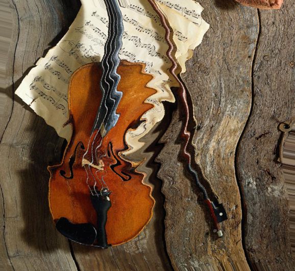
Unfortunately, it is phase garbled. The following image is phase-flat, but tonally colored.
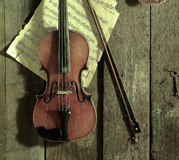
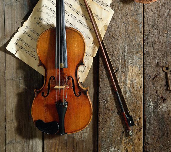
Both images are distorted, and some will prefer one over the other and, possibly, over reality:
Why wouldn't everyone prefer reality? Perhaps, because some have never heard anything close to it from any loudspeaker. In Post 358, I recount my experiences at the 2016 RMAF:
Wow, cascading quotes. The key takeaway here is that most passive crossovers, such as 2nd-order, 3rd-order, and 4th-order crossovers, even famous ones such as the Linkwitz-Riley LR2 and LR4, mangle the signal's phase. For a crossover to be truly accurate it not only must it yield a flat frequency response, it must also deliver a flat phase response. As for time alignment, that task is for the loudspeaker cabinet designer and maker to fulfill.
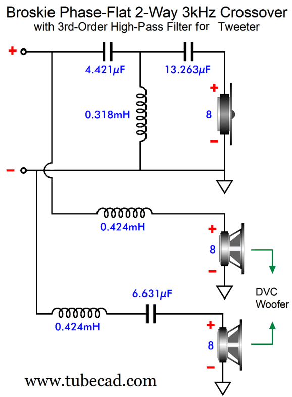
Broskie Phase-Flat Crossover Addition
Note that neither of the DVC driver's voicecoils needs a Zobel network to neutralize the voicecoil's inductance, as that inductance can be subtracted from the two 0.424mH inductor inductances: an electrical freebee, in other words, which is something relatively rare. Had I drawn the schematic with the bottom inductor near the driver, this possible freebee would be more obvious. By the way, inductors can be placed in series to build a higher amount of inductance, just as capacitors can be placed in parallel to create higher values of capacitance. In other words, the 6.631µF capacitor could be straddled by two 0.212mH inductors with no ill effect. The assumption behind this crossover design is that tweeters need the protection provided by the steep 3rd-order cutoff slope. In general, this is true, but not always. Sometimes we need to truncate the woofer's output more than we need to protect the high-frequency driver. For example, say we wanted to wed a big but slow woofer to nearly fullrange electrostatic panels or planar drivers or just high-quality fullrange drivers (either with dual voicecoils or two drivers). The sooner we can get the woofer's sluggish output out of the way of its fast partner the better. In other words, we need an inversion of this crossover, which cuts off the woofer's frequency response output with a 3rd-order Butterworth low-pass filter, while the high-frequency driver receives the lumpy 1st-order cutoff slope.
(I can imagine the optimal headphone setup, where the active version of this crossover is used to feed the headphone drivers a time-delayed, high-pass filtered signal and the subwoofers see the 3rd-order low-pass filter. Bass slam and thud with sweet, articulate, and phase-flat headphone glory. Your spouse or roommate or, even, neighbors may not like it, but the sonic splendor would be worth it.)
This crossover will not work with a current-output power amplifier, as the resulting load impedance is not flat, the impedance falling to half its nominal value at the crossover frequency. Note that only the DVC voicecoil that connects to capacitor C3 needs a Zobel network, as we can once again use driver inductance (Le) as part of the crossover design. As I pondered the question—Why can't we find some use for the top voicecoil's inductance?—I came up with a three-way phase-flat crossover based on this topology.
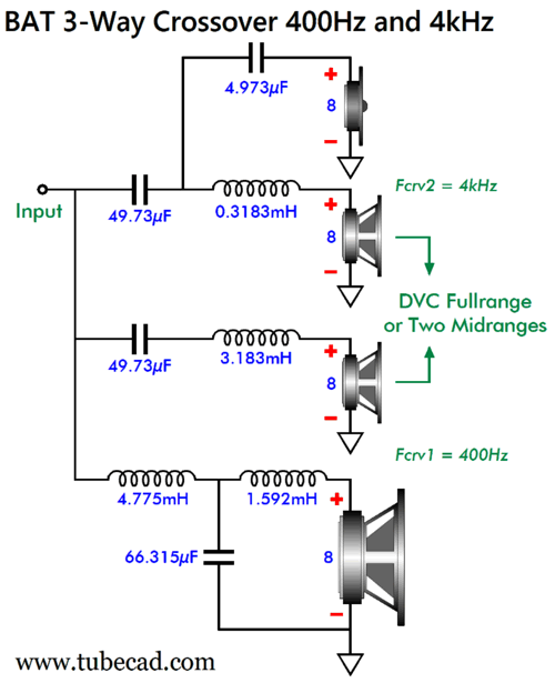
BAT 3-Way Crossover
Note how we can subtract the driver inductance from inductors L2, L3, and L4. When simple works, it's wonderful. Here a slight variation on this topology, so as to go partially series.
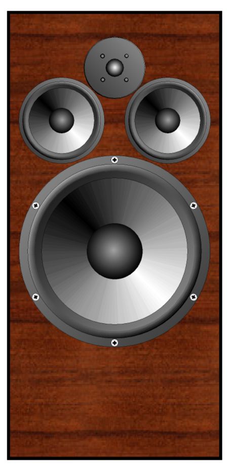
If we used two midrange drivers, this is what the cabinet might look like:
Here is the SPICE-generated frequency-plots graph.
Note that the tweeter sees a 1st-order slope below 4kHz and then a 2nd-order slope below 400Hz. The phase plot is as flat as the speaker-sum plotline, which means that this crossover can pass an undistorted square wave. Here are the crossover part values needed for the 400Hz and 4kHz crossover frequencies.
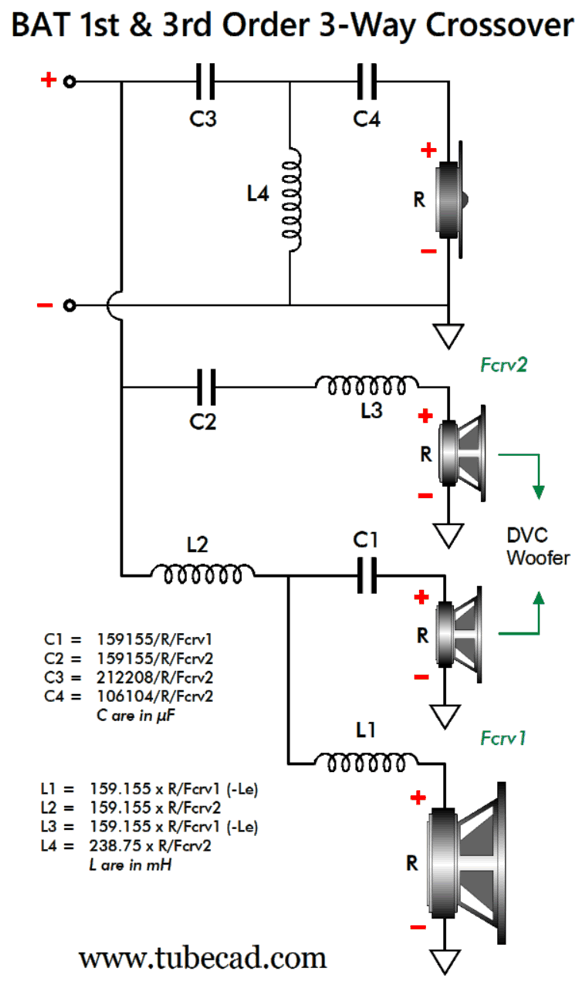
Of course when actually building such a loudspeaker, we would round the capacitor values up to 5µF and 50µF and 68µF; the inductor values to 0.32mH, 1.6mH, 3.2mH, and 4.8mH. We could easily bi-wire this crossover, with the tweeter and one of the midrange drivers getting one cable, while the woofer and the other midrange driver get the second run of loudspeaker cable. (I would actually use two 4-ohm woofers wired in series, with one firing forward, the other mounted on the rear of the cabinet, firing rearward, so as to eliminate bass diffraction loss and cabinet motion due to Newton's 3rd Law of Motion, i.e. for every action, there is an equal and opposite reaction; in other words, when one object exerts a force on another, the second object exerts an equal force back on the first object, but in the opposite direction. Therefore, the two woofers in-phase, but in opposing direction of motion will cancel, creating no cabinet motion. Well, we can invert this topology, so the tweeter gets the 3rd-order high-pass filter. We would still use either a DVC woofer or two midrange drivers.
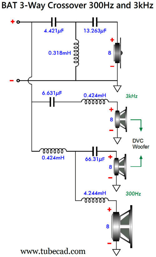
Note that the woofer now sees a staggered dual-slope cutoff, one at frequency Fcrv1 and another at Fcrv2. Also note that the DVC voicecoil that attaches to capacitor C1 needs a Zobel network. Here is a design example, with crossover frequencies of 300Hz and 3kHz.
Dang, I sure like the look of this crossover topology and its crossover frequencies. Once again, I would use two 4-ohm woofers wired in series, with one firing forward, the other mounted on the rear of the cabinet, firing rearward. Or, perhaps better still would be four 6in to 10in 8-ohm woofers, two on the front and two on the rear. Since we have quadrupled the woofer surface area, we gain +12dB in SPL, but as each woofer only sees half the input signal, we lose -6dB, netting a total of +6dB; but as a narrow cabinet will suffer a -6dB low-frequency loss due to diffraction loss, we return to unity. In other words in this setup, all six drivers (four woofers, one DVC midrange driver, and one tweeter) can share the same SPL per watt at one meter. Here are the SPICE-generated frequency plots.
Next, the phase graph.
What's not to like? Well, I wondered if I could devise a phase-flat 3-way crossover that delivered 3rd-order cut-off slopes to both the woofer and the tweeter. I could.
Double 3rd BAT Crossover
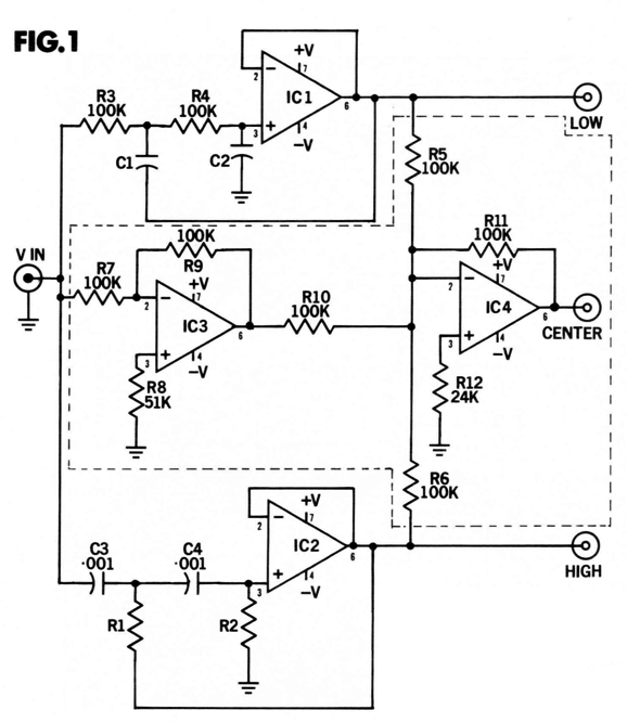
When I said a close-up examination I meant it. Note the 0.05dB vertical increments. Note the bat-wing plot. Well, I see the outline of the top of bat wings. In addition, I know that if something is not named, it doesn't fully exist in our consciousness. (I remember being irked when someone told me that the best thing about my Aikido gain stage was—not its low distortion nor its amazing PSRR nor its low output impedance—but its name. Aikido is the martial art that uses one's opponent's aggression against him, while the Aikido circuit uses the power-supply noise against it. I now realize that he was more right than wrong.) Next, let me explain how I went about creating this novel crossover. First, I knew that it a workaround was possible with an active crossover, as I had seen it over half a century ago in 1972 while in high school. The laudable old audio-construction magazine, Audio Amateur, published an article on active crossovers by Edward T. Dell Jr. and Joshua I. Goldberg. In fact, the magazine went on to sell kits based on the article's circuit, shown below.
The way this circuit works is simple enough. OpAmps IC1 and IC2 form Sallen-Keys 2nd-order active filters, which can be either Butterworth or Linkwitz-Riley alignments. OpAmp IC3 is configured as a simple inverting unity-gain stage. OpAmp IC4 does the magic by delivering the needed midrange signal that creates a perfect signal null at the junction of resistors R5, R6, R10, and R11, which is only possible if the LOW, CENTER, and HIGH output signals sum to a perfect inversion of the input signal. If the low and high filters are limited to 1st-order, then the CENTER output will be 1st-order bandpass output signal with -6dB-per-octave slopes and without bumps, as all three drivers will be down -3dB at the crossover frequencies—just like the passive three-way crossover yields. It's only when the low and high filters are greater in order that the bumps appear. My friends and I bought these kits, but we soon realized that they didn't deliver symmetrical cutoff slopes when used with 2nd-order filters and with three-way configurations, as the midrange driver only saw 1st-order bandpass filtering. Worse, the midrange driver saw bumps at the crossover frequencies, which the delicate midrange drivers had a hard time handling. Unknowingly, they had created a phase-flat active three-way crossover, but the average audiophile wanted symmetrical steep slopes even if it mangled the phase, as few thought about phase back then. In my post 474 , I created a variation upon their circuit that included a workaround for the problem of the tweeter's own resonant frequency (Fs). Returning to the present, I also knew that a passive implementation of the active phase-flat crossover might not be possible, as we can do many things actively that are close to impossible to do passively. My first step was create a SPICE circuit that would reveal what the midrange driver's frequency plot and phase plot would need to be to establish both a flat frequency response and flat phase response when all three drivers were summed.
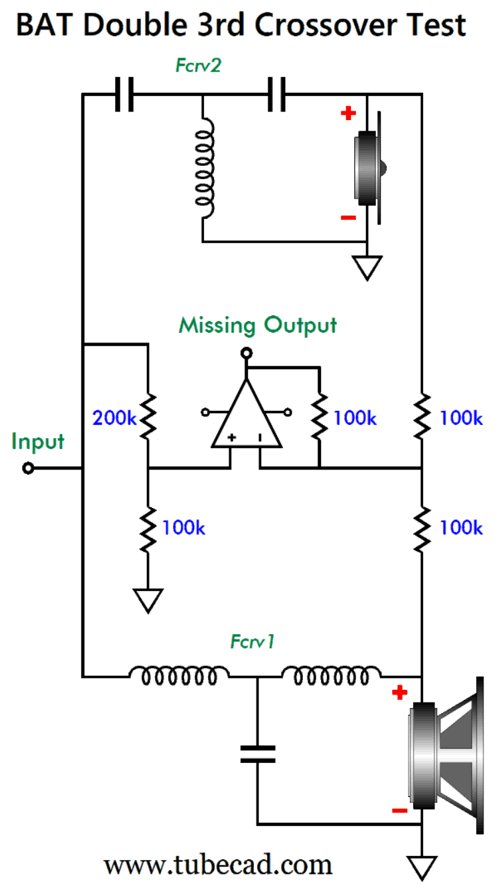
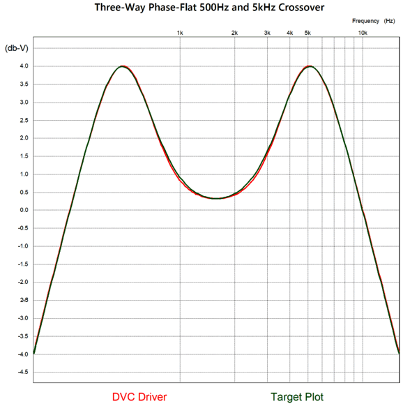
Fortunately, SPICE includes a model for the ideal OpAmp, so ideal that it can deliver thousands of volts and amperes of output into a 1-milliohm load. In addition, it fulfils the OpAmp's goal of always maintaining the same signal at both its inverting and non-inverting inputs. The missing output in signal amplitude versus frequency graph delivered another bat-like plot.
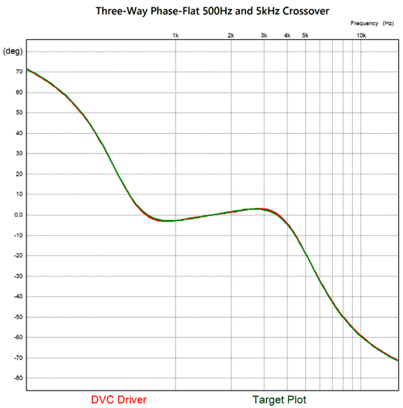
(Surely, I am not the only one who sees bat ears silhouette?) The green plotline is the target that I had to hit. Since it contained peaks of 4dB, I knew that the DVC driver would be needed, as that type of driver could deliver up to 6dB of greater output. The red plotline reveals how close I managed to hit the target. In addition, I needed to know what the needed phase plot would look like, as it, too, needed to be hit.
Note how the target plot intersects zero degrees at 1581Hz, which is the geometric center frequency of 500Hz and 5kHz, i.e. Fgeo = √(500 x 5000). Believe me; it took some intense head scratching to devise a passive topology that could match the target plots, especially as my brain transitions from platinum to mere silver with age.
Since the woofer's crossover frequency is 500Hz and the tweeter's is 5kHz, why does the DVC driver see 523.5Hz and 4778Hz crossover frequencies? In order to create the 4dB peaking required skewing the crossover frequencies. The 300-ohm resistor is kludge or sorts. Ideally, it should be replaced with an elaborate RCL network. The only problem with the RCL network replacement is that it will probably demand a truly huge inductor value, as in 100mH due to the 300-ohm resistance. (Of course, the needed capacitor value would prove amazingly small due to that same 300-ohm resistance.) I was about to write that the resistor trick was good enough for government work, but actually, as the above and the below plotlines reveal, it is about a thousand times better than what government work expects.
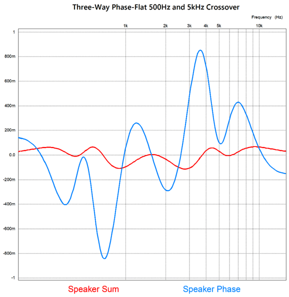
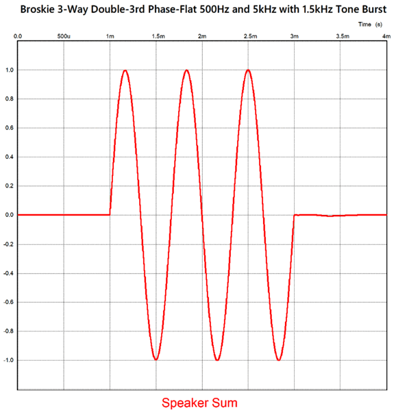
The phase is flat within 1 degree and the amplitude is flat with 0.1dB across the audio bandwidth. We finally come to the real test: a tone burst of three cycles of a 1.5kHz sine wave to test the crossover's ability to deliver a transient-perfect output.
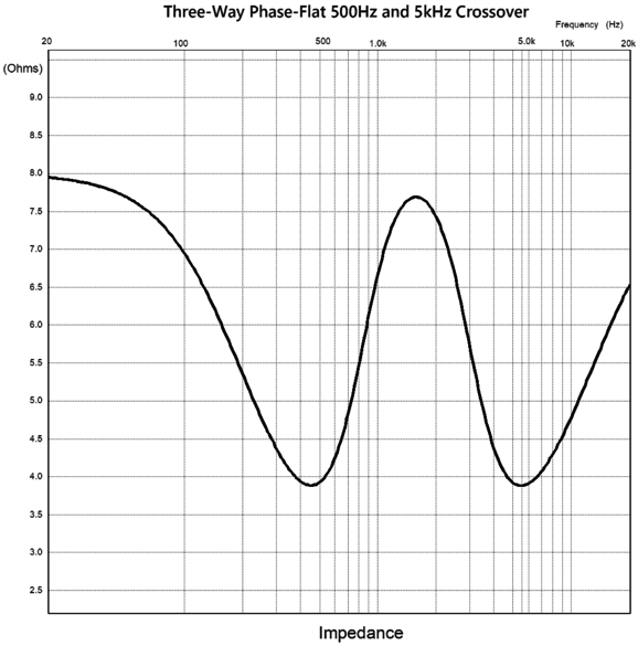
Dang fine! Three cycles go and three come out. Alas, we must pay for this waveform fidelity, and what we end having to give up is a flat load impedance.
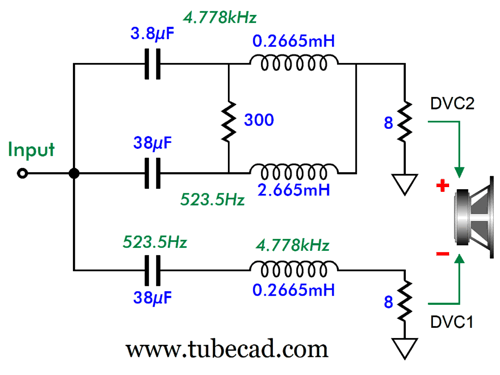
Note that all loudspeaker drivers are 8-ohms. Here is the complete BAT Double 3rd crossover topology:
Here are the crossover part values for the 500Hz and 5kHz crossover frequencies. The woofer's and the tweeter's 3rd-order filters are pure textbook 3rd-order Butterworth designs.
What about the part values needed for the DVC driver (or two midrange drivers)? Here we run into some issues. First, the resistor value varies with the ratio between the higher crossover frequency divided by the lower crossover frequency. Why isn't resistor R1's value constant? Each ratio requires a different amount of boosting at the geometric-mean frequency, which the resistor accomplishes.
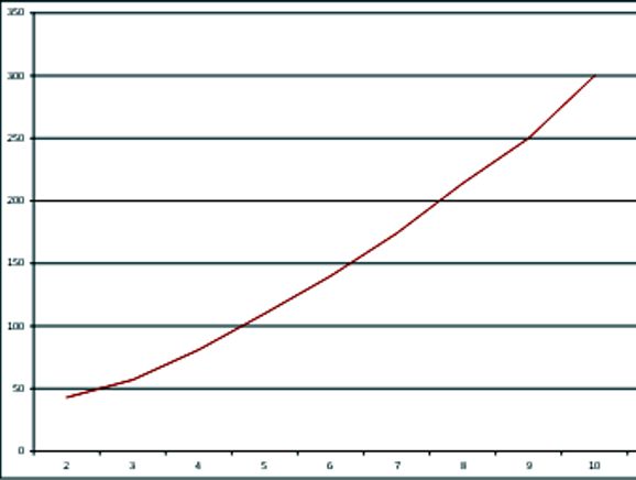
The amount of needed boost is the multiplicative value, not dBs. With a ratio of 2, the 43-ohm resistor value is so low that it muddies the other part values to the point that I cannot recommend using it at all. Here is the Excel chart of resistance versus ratio.
Here is the math needed for BAT Double-3rd crossover with a ratio of 1:10.
I can easily imagine a loudspeaker system using this crossover with crossover frequencies of 200Hz and 2kHz, along with a DVC 6in driver and ribbon or planar tweeter, as these types often exhibit flat impedance and phase plots. Okay, but what if you desire a three-way crossover with a ratio of 1:3, as you want to cross over at 300Hz and 900Hz, say using a 12in woofer with two 8in midrange driver-woofers and a horn midrange driver-tweeter? Well, you are in luck, as I used SPICE to work out all the needed part values for that crossover.
The DVC capacitor and inductor values do not match the formulas provided for the crossover with a 1:10 ratio, but have been tweaked to work with the ratio of 1:3. No doubt some are thinking. "That's great, but I need 600Hz and 1800Hz." The solution for the 600Hz and 1800Hz 3-way crossover is to halve all the capacitor and inductor values, but not the resistor R1's value. In other words, as long as the ratio between crossover frequencies is 1:3, we simply divide 300Hz by the desired lower crossover frequency and multiply the result against all the capacitor and inductor values. For example, if the lower crossover frequency is 100Hz, then we divide 300Hz by 100Hz and get 3, which we multiply against all the capacitor and inductor values, as all must be three times greater in value. If the desire crossover frequencies were 900Hz and 2700Hz, we would one third all the capacitor and inductor values, as 300Hz/900Hz equals one third, i.e. 0.3333... For the ratio of 1:4, I used crossover frequencies of 200Hz and 800Hz. This means that if the ratio between crossover frequencies is 1:4, we simply divide 200Hz by the desired lower crossover frequency and multiply the result against all the capacitor and inductor values. For example, say we want 500Hz and 2kHz as crossover frequencies, so the multiplier is equal to 200/500 or 0.4.
Next, we see a ratio of 1:5, with crossover frequencies of 300Hz and 1.5kHz.
We move on to a ratio of 1:6.
Next, we see a ratio of 1:7, with crossover frequencies of 300Hz and 2.1kHz.
Next, we see a ratio of 1:8, with crossover frequencies of 200Hz and 1.6kHz.
Finally, we see a ratio of 1:9, with crossover frequencies of 200Hz and 1.8kHz.
What if you want crossover frequencies of 200Hz and 1.1kHz, which makes a ratio of 5.5? Well, the formulas shown for the 1:10 ratio crossover work well with ratios 1:5 up, so they can be used. The problem is resistor R1's value. We know that a ratio of 1:5 requires a resistor of 110 ohms and a ratio of 1:6 needs 140 ohms, so we can add the two together and get 250 ohms, which we then divide by two to get 125 ohms as the extrapolated resistor value. Or, you can look at the Excel graph shown above to locate the required resistor R1 value. Ideally, if you have access to a good SPICE program, then you can model the crossover to fine tune the values.
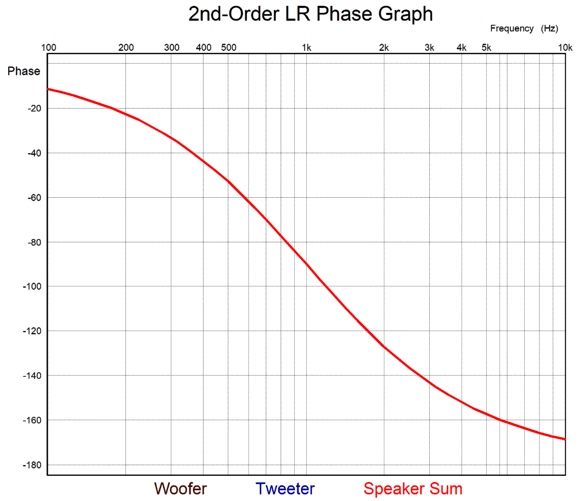
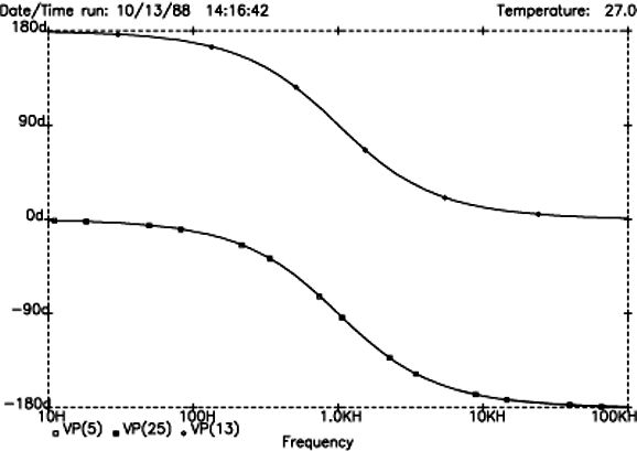
Linkwitz-Riley 2nd-Order Transient Accurate?
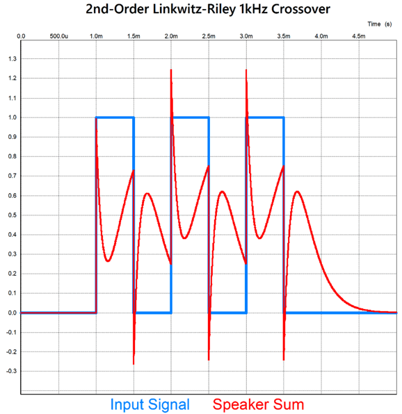
The graph is based on a crossover frequency of 1kHz and shows -90 degrees of phase shift at 1kHz. If we deliver three cycles of positive pulses with a pulse period of 1ms (i.e. 1kHz), we get the following summed output.
Does this look at all transient accurate to you? If we subtract the blue input signal trace, could you recognize three positive pulses in the red trace? Moreover, having both the woofer and tweeter in phase with each other across the audio spectrum has never been a requirement for a phase-flat, transient-accurate crossover. For example, the 1st-order 2-way crossover is universally acknowledged as being both phase-flat and transient-accurate, but its woofer and tweeter differ by a constant 90 degrees of phase shift throughout the audio bandwidth. I searched the web for the origin of the false attribution of transient-accurate to the Linkwitz-Riley alignment. Well, I discovered a 2005 PDF by the Rane Corporation, written by Dennis Bohn and titled, RaneNote 160. The article is informative and well written, save for the section titled, "LR-2, Transient Perfect 2nd-Order Crossover." Here Bohn shows the LR2 phase shift:
And he points out how the tweeter must be wired out of phase, which will prevent a huge suck-out at the crossover frequency and will cause the two plots to overlap. He then somehow concludes that this results a transient-perfect summed output. It simply doesn't. Yet, he shows a graph that claims to reveal a near transient-perfect step response:
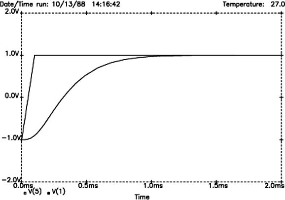
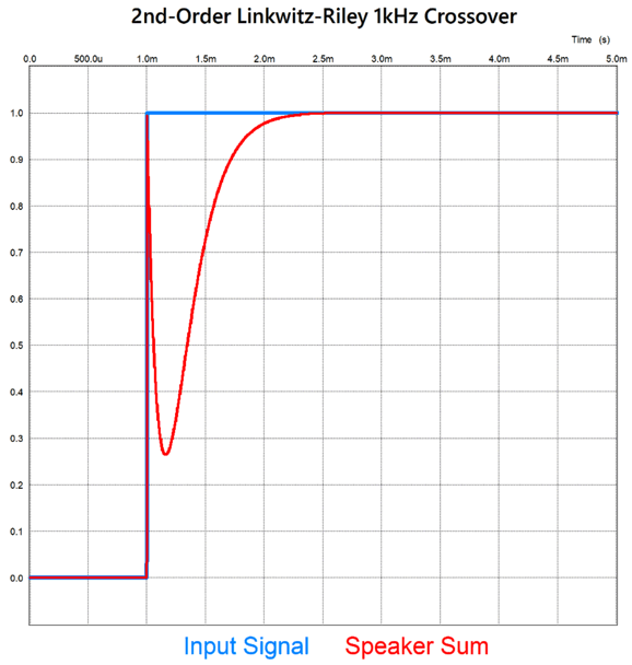
There's no way that two -1's add up to positive 1. Perhaps, he reasoned that since making a power amplifier frequency-flat also makes it phase flat, making a loudspeaker frequency will also prove phase flat. Sadly, it doesn't. Yes, the Linkwitz-Riley alignment yields flat frequency response, unlike the Butterworth or Bessel alignments, but it still mangles the phase. But where did his graph come from? My guess is that he didn't apply a small time delay (1ms) to his SPICE transient test, which caused him not to see the entire picture, only the slow ramp up to 1. Here is a 1V step voltage applied to the Linkwitz-Riley 2nd-order 1kHz crossover in SPICE simulation with a 1millsecond time delay before applying the positive pulse.
Note that the summed output sharply slams up to 1 and then relapses down to about 0.27 before slowly climbing up to 1 again. This is not transient-perfect. In addition, the SPICE test assumes infinite bandwidth for both the woofer and tweeter. If we include actual loudspeaker driver failings, the step response will jumble even more. Nonetheless, the article is well worth reading as it points out the importance of driver time alignment and the lobing effects of the Butterworth and Linkwitz-Riley crossover alignments.
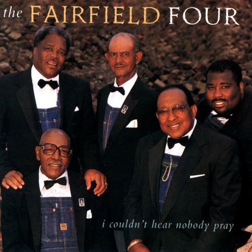
Music Recommendation: The Fairfield Four's I Couldn't Hear Nobody Pray
The last sentence startled me, as I found the recording quality excellent. If nothing else, it's thrilling to hear the deep bass from the late Isaac "Dickie" Freeman's vocal cords and lungs. Dang. He can sing and sing looow. I would love to hear this album reissued in a high-res format, but the 16-bit and 44.1kHz format offered now still sounds great.
//JRB
Did you enjoy my post? Do you want to see me make it to post 1,000? If so, think about supporting me at Patreon.
User Guides for GlassWare Software
For those of you who still have old computers running Windows XP (32-bit) or any other Windows 32-bit OS, I have setup the download availability of my old old standards: Tube CAD, SE Amp CAD, and Audio Gadgets. The downloads are at the GlassWare-Yahoo store and the price is only $9.95 for each program. So many have asked that I had to do it. WARNING: THESE THREE PROGRAMS WILL NOT RUN UNDER VISTA 64-Bit or WINDOWS 7, 8, and 10 if the OS is not 32-bit or if it is a 64-bit OS. I do plan on remaking all of these programs into 64-bit versions, but it will be a huge ordeal, as programming requires vast chunks of noise-free time, something very rare with children running about. Ideally, I would love to come out with versions that run on iPads and Android-OS tablets.
|
I know that some readers wish to avoid Patreon, so here is a PayPal button instead. Thanks. John Broskie
John Gives
Special Thanks to the Special 94! To all my patrons, all 92 of them, thank you all again. I want to especially thank
I am truly stunned and appreciative of their support. In addition I want to thank the following patrons:
All of your support makes a big difference. I would love to arrive at the point where creating my posts was my top priority of the day, not something that I have to steal time from other obligations to do. The more support I get, the higher up these posts move up in deserving attention.
If you have been reading my posts, you know that my lifetime goal is reaching post number one thousand. I have 378 more to go. My second goal was to gather 1,000 patrons. Well, that no longer seems possible to me, so I will shoot for a mighty 100 instead. Thus, I have just 8 patrons to go. Help me get there. Thanks.
New URL of the GlassWare website |
||||||||||||||||||||||||||||||||||


| www.tubecad.com Copyright © 1999-2025 GlassWare All Rights Reserved |