| John Broskie's Guide to Tube Circuit Analysis & Design |
| March 20 2026 | Post Number 635 |
||||
A Loudspeaker for Class-D Output stage efficiency is evaluated at full power output. This makes sense in an industrial setting, where a high-power amplifier might be employed to rattle a shaker table. The more efficient at full output, the better, as wasted energy is wasted money. What about at idle, when the amplifier puts out no signal? As output stage efficiency is the ratio of the useful output to the total input, the class-D amps exhibit ZERO efficiency at idle, as they still dissipate heat. Here is what Gemini AI had to say:
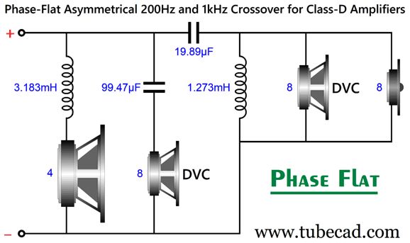
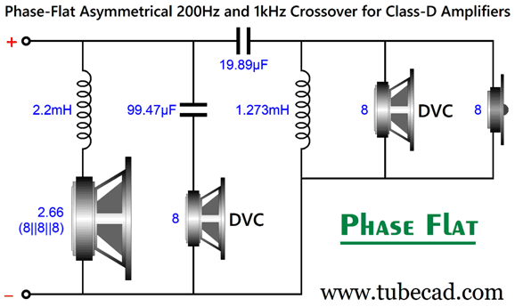
In contrast at idle, the class-B amplifier only has to power the input stage, as its output devices draw no current. In addition, good music holds a lot of quiet parts and, often, no music plays as we cannot make up our minds on what to listen to next. In the world of audio-equipment production, the true class-D "efficiency" is found in its tiny heatsinks, as heatsinks are both heavy to lift and expensive to buy and to ship. Long ago, I predicted here that once class-D power amplifiers became less expensive than high-quality capacitors and inductors, loudspeakers makers would jettison big, expensive high-quality capacitors and inductors and move to using internal power amplifiers with internal active crossover filters, filters that used tiny and inexpensive parts. Interestingly, it seems as if only the very cheap and the very, very expensive home loudspeakers now hold class-D amplifiers (and often only to power an integral subwoofer). In car-audio systems, however, class-D amplifiers rule, as they can run off the 12V battery, yet drive 2-ohm speakers readily—and loudly. Well, this brings up the related topic of purposely making a low-impedance home loudspeaker to take advantage of class-D amplification, as class-D amplifiers become more common in home audio equipment. Unlike conventional solid-state power amplifiers, class-D amplifiers prefer low-ohm loads. Since our aim is for high-quality sound, wide and flat frequency bandwidths and flat-phase responses are worthy goals. Here is one possible example:
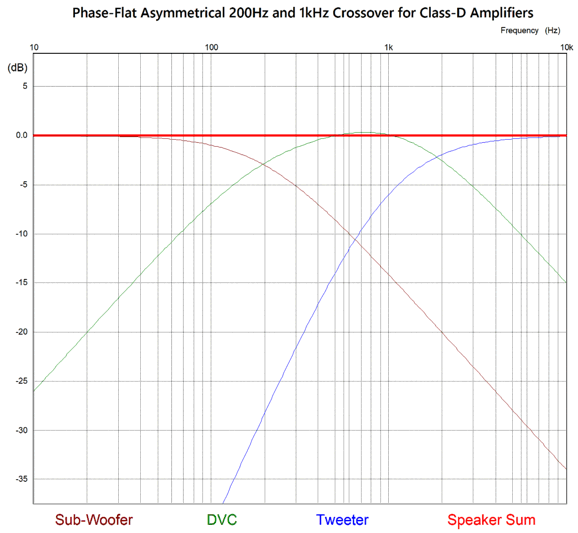
In spite of what you see, only three speaker drivers are needed, as one is a dual-voicecoil driver (DVC), and only four reactive parts (capacitors and inductors) are used, which is amazing for a three-way system with 2nd-order high-pass filter for the tweeter with a flat-phase output. (Of course when building this crossover, we would actually use a 3.2mH and 1.3mH inductors, with 100µF and 20µF capacitors.) The asymmetrical aspect lies in the 2nd-order high-pass filter slope for the tweeter, but 1st-order slopes for the subwoofer and DVC driver.
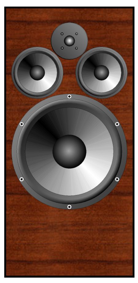
Note that the tweeter is down -6dB at its crossover frequency of 1kHz. Also note that the DVC driver peaks a tad over the 0-dB line, the result of both of its voicecoils being engage at once. As DVC drivers are woefully rare, we could replace it with two midrange drivers. The following example remains a three-way loudspeaker in spite of the four drivers.
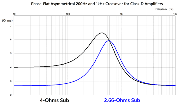
The price we pay for the low-part count and flat-phase output is a non-flat load impedance.
If you are wondering about how we get a 2.66-ohm woofer, the answer is that we place three 8-ohm woofers in parallel.
Here is a SPICE-simulation test that reveals whether a loudspeaker crossover is truly flat-phase or not: the three-cycle tone burst.
This is what waveform fidelity is all about. In comparison, the super popular Linkwitz-Riley crossover alignment is not phase flat. Instead, it is advertised as being "phase coherent," which just means that the woofer and tweeter both follow the same twisting phase in unison. Although it can produce a flat frequency response, it cannot deliver this clean tone-burst. Here is how the Linkwitz-Riley 2nd-order, two-way crossover responds to the 1kHz three-cycle tone burst:
Next, we see how it handles a square-wave input signal:
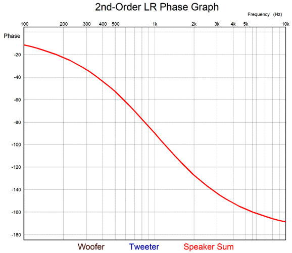
Mind you, if I had shown the transient graphs for a three-way Linkwitz-Riley 2nd-order crossover, the results would have been far worse. Next, we see its phase plot:
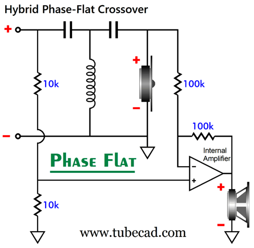
Hybrid Phase-Flat Crossover
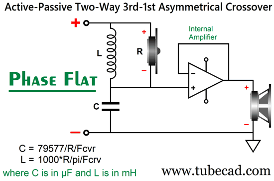
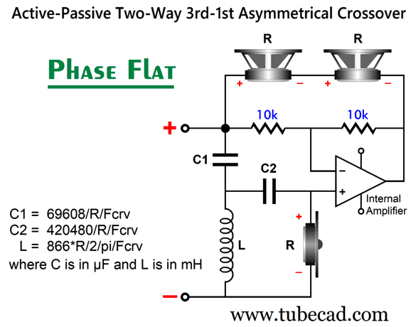
The way this works is the internal power amplifier, with the four attached resistors, is configured as a differential amplifier that only passes differences: if both input resistors terminate into the same signal, nothing emerges from the amplifier's output. In this setup, its noninverting input sees the output signal from the external power amplifier, while its inverting input sees the tweeter's input signal. The internal power amplifier then alters its output until it conforms to that of the external power amplifier's output. The result is a flat frequency response and phase response, assuming flat drivers, as that output is a perfect complement to the 50% attenuated input signal at the non-inverting input. The way we get extra SPL from the woofer is either to alter the resistor ratios in the differential amplifier or by using a large, low-ohmage woofer, such as DVC subwoofer with both its (8-ohm) voicecoils wired in parallel. The potential downside to this setup is that the load impedance is not at all flat, as only the tweeter is driven by the external power amplifier. In other words, the impedance rises with lower frequencies, well on a path to infinity—until the two 10k differential-amplifier resistors put a hard stop at an impedance of 20k. This may not be a problem with a solid-state power amplifier, but it won't make a tube-based power amplifier happy that runs feedback-free (or a current-output amplifier). My workaround is to use two woofers, so as to produce low-frequency loading—but first, let's take a look at the voltage relationships with a 1st-order high-pass filter used as a tweeter crossover.
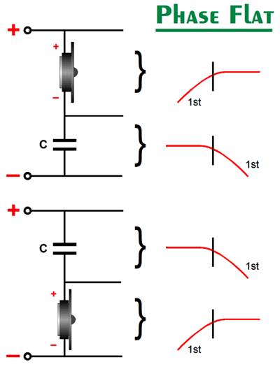
As far as the tweeter is concerned, both arrangements yield the exact same results. If this does not make sense, try replacing in your mind the tweeter with a resistor. If it still doesn't make sense, realize that there's no ground in this circuit. Yes, terminals are marked negative, but that is not the same as ground. The right curly bracket means "taken differentially." Speaking of things differential, transformers are intrinsically differential electrical devices; attach both primary leads to the same input signal, and nothing emerges from the secondary.
Note that this circuit does hold a ground, i.e. a signal reference, but only on the secondary sides. If we place both transformer secondary outputs in parallel, their voltages summed must yield a flat frequency and phase response, as those two secondary signals are perfect complements that create a frequency-flat and phase-flat summation. It has to be, due to Kirchhoff's laws that state that “The algebraic sum of all currents entering and exiting a node must equal zero.” and "The directed sum of the potential differences (voltages) around any closed loop is zero." I go into how this applies to series crossovers in Post 481. Many know that the 1st-order crossover sums to frequency and phase flat, so this makes sense. But what about 2nd-order high-pass filters? Same thing.
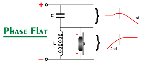
The mirrored symmetry of the 1st-order high-pass filter is gone, but the set of two signals still sum to frequency and phase flat. Here is an alternative arrangement.
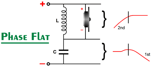
In spite of looking upside-down, the same results obtain. Now, if we call the negative input terminal ground, and if we add a bipolar power-supply to that ground connection, we can treat the tweeter's negative terminal's connection to the capacitor as the source of the input signal for an internal power amplifier.
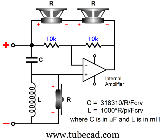
The impedance load presented to the external power amplifier, however, is still not flat. If we use an inverting internal power amplifier and flip the 2nd-order capacitor and inductor, we can use this topology.
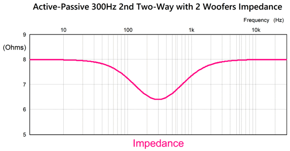
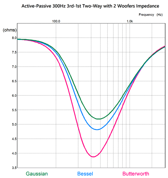
Now, the external power amplifier must drive the tweeter and two woofers (with the help of the internal power amplifier). Assuming 8-ohm drivers and a crossover frequency of 300Hz, we get this resulting impedance plotline.
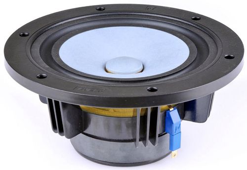
At its lowest point, the impedance drops to 6.4 ohms. Not bad, as some high-end loudspeakers (nominally 8-ohm) have dropped to 1-ohm. Yes, the two woofers in series present a 16-ohm load, but the inverting internal power amplifier inverts the external power amplifier's output at low frequencies. In other words, it doubles the output voltage from the external power amplifier while only matching its output current. Since the two woofers present twice the radiating surface area of a single woofer, the SPL increases by 6dB. Thus, two 88-dB woofers could be used with a 94dB fullrange driver. Moreover, the three drivers could be arranged in the MTM (midrange-tweeter-midrange) aka D'Appolito configuration. I chose the 300Hz crossover frequency for this example, as I had Markaudio's excellent fullrange drivers in mind, not a one-inch dome tweeter.
Freed from the onerous task of producing low-frequencies, the fullrange's clarity can soar. In addition, the 2nd-order high-pass filter greatly increases the fullrange driver's power handling ability. On the other hand, we could add a tweeter and still maintain a flat-phase response.
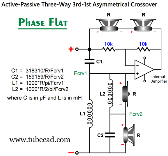
The midrange driver and tweeter see both a 1st-order crossover at the second crossover frequency, Fcrv2, and the 2nd-order crossover at Fcrv1. The cascade of slopes further protects the tweeter, which might crossover at 6kHz or higher. If greater protection of the midrange driver is needed, we can use a 3rd-order high-pass filter.
If the math in the formulas does not look right for a Butterworth 3rd-order high-pass filter, the reason is that the filter's alignment is Gaussian. What? Most of heard of the Bessel (aka Thomson), Butterworth, and Linkwitz-Riley, but few know about the Gaussian alignment. In the 3rd-order instantiation, the Gaussian results in the tweeter being -7.3dB down at the crossover frequency and exhibits a truly low Q of 0.43, but this proves to be a feature in this crossover. (There is no Linkwitz-Riley 3rd-order alignment.) Wikipedia informs us:
Audio and Uncertainty Principle, won't our friends be impressed? By the way, audioxpress.com offers a good overview of the various filter alignments in regards to bass-reflex loudspeaker design. The reason I adopted the Gaussian alignment in this topology is that it offered the least dip in impedance.
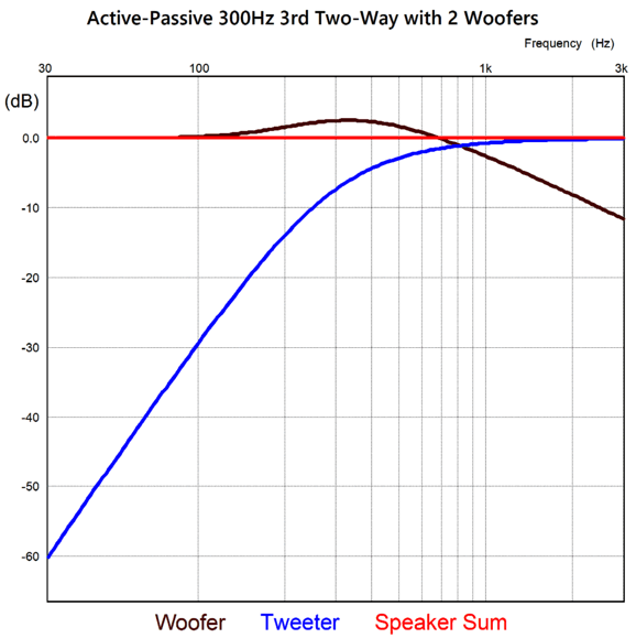
The typical 3rd-order Butterworth delivered the deepest dip. Not good. Here is the frequency plots for a 300Hz crossover frequency.
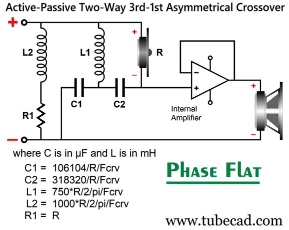
The phase plotline is as flat as the frequency plotline. Note that the tweeter (or fullrange driver) is down -60dB at one decade below the crossover frequency, which means that only 1/1000 of the signal that the woofer sees at 30Hz is delivered to the tweeter. What if we don't let the external power amplifier drive any woofers? Well, we could then use the Butterworth alignment, as it uses smaller valued crossover capacitors and inductors.
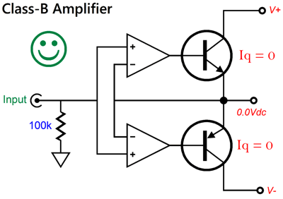
I can easily imagine many raised eyebrows due to the inclusion of the added inductor (l2) and resistor (R1). They were added to give the external power amplifier something to bite on at low-frequencies. Won't the resistor get hot? It might, but probably not with an 8W flea-powered single-ended, tube-based amplifier. In addition, we can use cheap parts, such as sand resistors and ferrite-core inductors, as they produce and pass no sound, serving only as a low-frequency load. No doubt, many assume a class-D power amplifier would nestle itself in the loudspeaker enclosure, but a class-B amplifier/power-buffer could be used. In my last post, we saw this example.
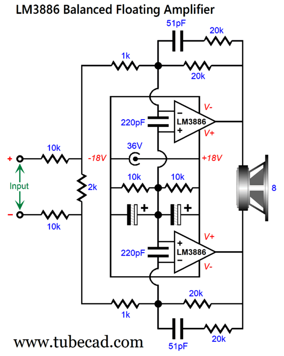
This simple design could be used with either high-current OpAmps or with Darlington output transistors. Alternatively, we could use the famous LM3886 chip power amplifier.
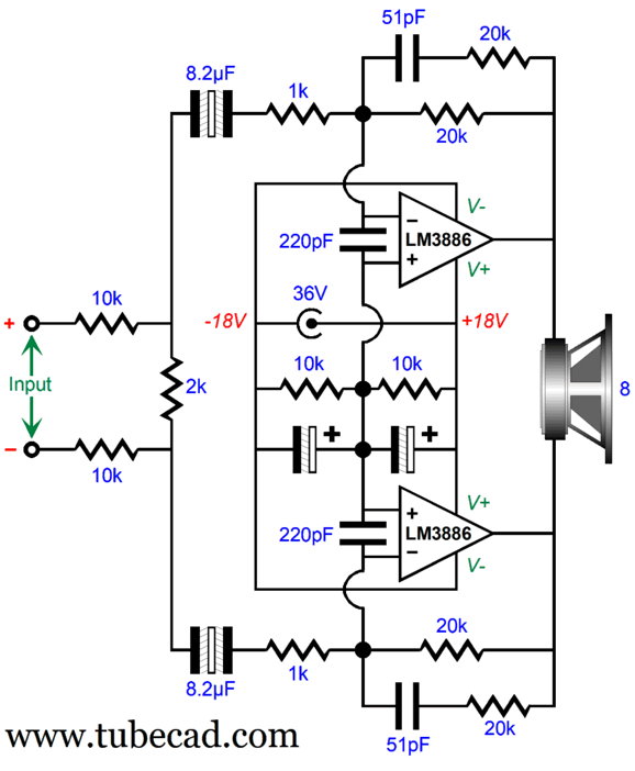
The LM3886 is nowhere near being unity-gain stable, thus the inclusion of the input attenuator made up from the two 10k and one 2k resistors. Note that there is no ground symbol in this circuit. The assumption here is that an external power supply, such as a desktop switch-mode power supply, would be used, so as not to take up any of the loudspeaker's internal cabinet volume and not to add any heat inside the cabinet. We can get fancy and add a low-frequency high-pass filter to prevent the woofer from going too deep into the subsonic region and to avoid DC offsets from being amplified.
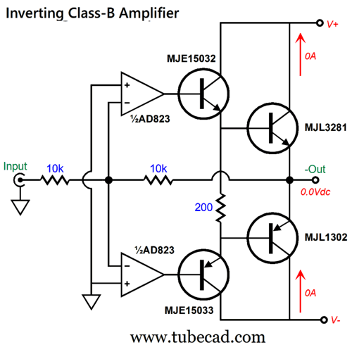
The added 8.2µF capacitors impose a 20Hz high-pass filter upon the LM3886 amplifier's output. With the external 36Vdc floating power supply, the two chip amplifiers can deliver around 50W, as each amplifier effectively sees a 4-ohm load. If I remember correctly, the LM3886 draws 50mA at idle, which means that two of them with the 36Vdc external power supply, they will dissipate a total of 3.6W of heat. What about those previous active-passive crossovers that held inverting internal power amplifiers? I would love to build the following inverting class-B amplifier.
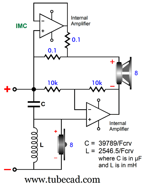
The two 1k resistors set the gain, which in this example is 1:-1 or, put differently, inverted unity-gain. But altering the resistor ratio, we can either deliver attenuation or amplification. Okay, what about those who prefer to use only one woofer with the inverting amplifier? If we assume a target impedance of 8 ohms, an impedance-multiplier circuit (IMC) works to double the woofer's impedance after it had been effectively halved by the inverting amplifier.
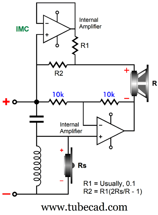
What if we want to use a single 4-ohm woofer with a 12-ohm tweeter? Then, we must alter the impedance-multiplier circuit's resistor ratio. Here is the more universal math.
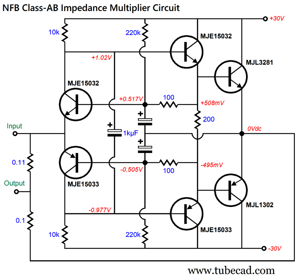
Posts 171 and 172 and 198 are good places to get an overview of the IMC concept. I would like to build and tryout the following impedance-multiplier circuit, which is based on my unity-gain power buffer from my last post.
The 0.11 resistor is a tad higher in value to its brother 0.1 resistor so as to compensate for the slightly less than unity-gain that the buffer delivers. In SPICE simulations, this circuit worked gangbusters, doubling the load impedance to the external power amplifier. To get to a negative temperature idle current flow function, the hotter the circuit becomes, the less the idle current flow, the two input transistors and the two output transistors must be attached to the same heatsink (and close together). In SPICE simulations, the idle current was a paltry 36mA.
I think it only fair to warn you that this post was only the warm up for my next post, where I subtract the passive portion of the crossover.
Music Recommendation: Dave Alvin's
//JRB
AI Summary Class-D Power Amplifiers:
Loudspeaker Design for Class-D Amplifiers:
Hybrid Phase-Flat Crossover:
Advanced Crossover Designs:
Music Recommendation:
Did you enjoy my post? Do you want to see me make it to post 1,000? If so, think about supporting me at Patreon.
User Guides for GlassWare Software
For those of you who still have old computers running Windows XP (32-bit) or any other Windows 32-bit OS, I have setup the download availability of my old old standards: Tube CAD, SE Amp CAD, and Audio Gadgets. The downloads are at the GlassWare-Yahoo store and the price is only $9.95 for each program. So many have asked that I had to do it. WARNING: THESE THREE PROGRAMS WILL NOT RUN UNDER VISTA 64-Bit or WINDOWS 7, 8, and 10 if the OS is not 32-bit or if it is a 64-bit OS. I do plan on remaking all of these programs into 64-bit versions, but it will be a huge ordeal, as programming requires vast chunks of noise-free time, something very rare with children running about. Ideally, I would love to come out with versions that run on iPads and Android-OS tablets.
|
I know that some readers wish to avoid Patreon, so here is a PayPal button instead. Thanks. John Broskie
John Gives
Special Thanks to the Special 91 To all my patrons, all 91 of them, thank you all again. I want to especially thank
I am truly stunned and appreciative of their support. In addition I want to thank the following patrons:
All of your support makes a big difference. I would love to arrive at the point where creating my posts was my top priority of the day, not something that I have to steal time from other obligations to do. The more support I get, the higher up these posts move up in deserving attention.
If you have been reading my posts, you know that my lifetime goal is reaching post number one thousand. I have 365 more to go. My second goal was to gather 1,000 patrons. Well, that no longer seems possible to me, so I will shoot for a mighty 100 instead. Thus, I have just 9 patrons to go. Help me get there. Thanks.
New URL of the GlassWare website |
||||


| www.tubecad.com Copyright © 1999-2026 GlassWare All Rights Reserved |