| John Broskie's Guide to Tube Circuit Analysis & Design |
| July 04 2026 | Post Number 642 |
||||
Happy 250th
I am now 28% as old as The United States of America. Yes, I am old, but I was once young. I was 20 years old at the 200th birthday of my nation—and only 10% as old as the nation back then. I experienced the 200th anniversary mostly from watching PBS historical documentaries and its drama miniseries, The Adams Chronicles. (I have always been a John Adams fanboy.) As I have been feeling extra patriotic of late, I plan on rereading the Declaration of Independence and US Constitution today. Not incongruously, I shall not being watching PBS or listening to NPR, to which I have donated and have the sweatshirts and tote bag to prove it. Why not? Long ago, I have certainly met my lifetime's obligation to endure ceaseless sniveling and relentless reiteration of the sin of slavery. I say no thanks to "Be depressed, damn you." On Beethoven's 200th birthday, the year 1970, I listened to all nine of his symphonies in a row. When the next Beatle passes and if I still live, I shall put the entire Beatles catalog on auto-play—possibly, including those that include Yoko.
Dual-Use Amplifier
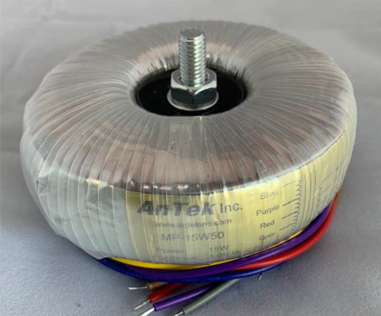
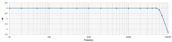
What first caught my attention was its wide and flat bandwidth. (Note the tiniest peak at 50kHz.) Second, its "strategically placed air gaps" really got me interested. Why? Push-pull output transformers do not need airgaps; single-ended output transformers do. Well, actually, push-pull toroid transformers also need one, albeit a small one. Here is why: toroid transformers hold such a tight magnetic circuit that any current imbalance can lead to core saturation.
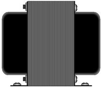
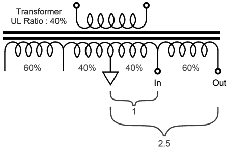
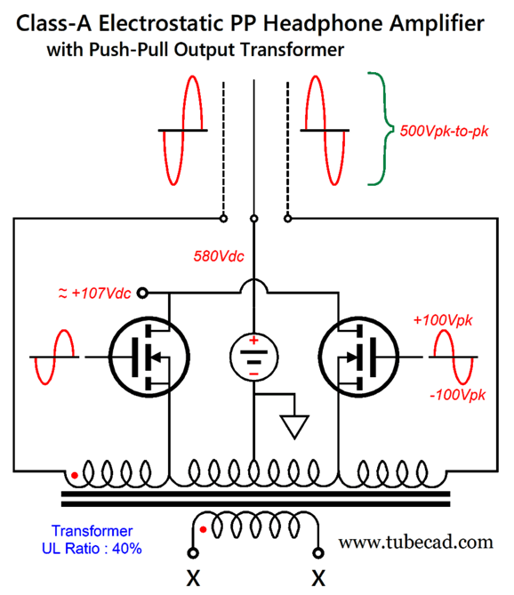
Old fashion I-and-E stacked output transformers inherently contain an implicit air gap due to the intrinsic slop of their core's magnetic circuit, which absorbs the minor current imbalance between output tubes. And the last feature to compel my notice was the ultra-linear taps at 40%. As this is the standard transformer practice, why pay it any notice? Electrostatic headphones. For years now, I have longed to build an electrostatic-headphone amplifier that utilized an ultra-linear output transformer, as its ultra-linear taps would allow me to get away with a much lower B+ voltage. How so? The ultra-linear taps, when driven, allow for bigger output voltage swings at the winding's ends.
If we ground the center-tapped and drive an ultra-linear tap, we get a 2.5X increase in voltage swing at the ends of the winding. Since the universe does not allow free lunches, we get only 40% of the output current swing, but this is less of an issue with electrostatic headphones, which are primarily voltage driven. (At high frequencies, the capacitance does require some current to charge up and discharge quickly. Fortunately, most music contains little high-frequency amplitudes.) With a step-up ratio of 1-to-2.5, we can drive both ultra-linear taps in a balanced fashion to ±100Vpk and get ±250Vpk at the stators, which is the output voltage swing that my all-tube electrostatic headphone amplifier delivers.
Although certain robust vacuum output tubes could be used in a cathode-follower configuration, low-wattage but high-voltage MOSFETs would allow for an even lower B+ voltage.
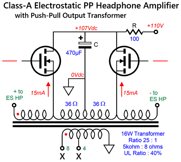
The secondary is left floating (and safely taped up). Note the paltry +107Vdc B+ voltage still allows huge output voltage swings. If a decent 5W push-pull output transformer were made, it could be used, as each MOSFET need idle at only 15mA. Using the AnTek output transformer, we get the following.
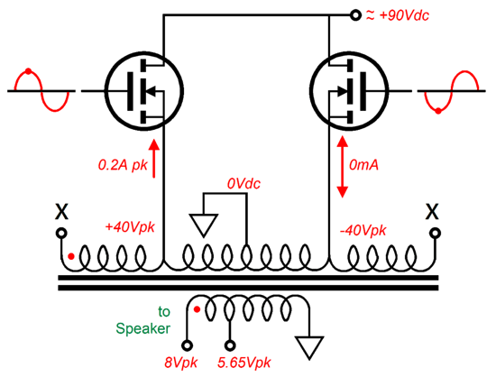
The ultra-linear taps span 40% of the primary's DCR of 180 ohms, so each segment presents 36 ohms of DC wire resistance, which we can use to monitor the current flow through the output MOSFETs, as 15mA against 36 ohms equals a voltage drop of 0.54V. The RC filter exhibits a -3dB cutoff frequency of 3.5Hz. What would happen if we upped the idle current to 0.1A per MOSFET?
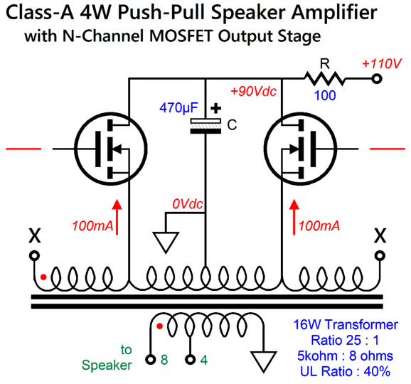
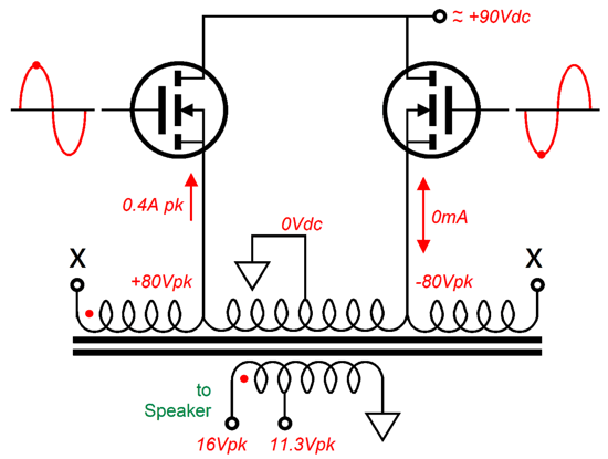
We get a class-A, push-pull speaker power amplifier, one suitable for driving horn or computer or desktop loudspeakers. Note that the increased idle current flow through the RC filter has dropped the B+ voltage to +90Vdc. This is okay, as the MOSFETs need only swing ±40Vpk each to get ±8Vpk into an 8-ohm load at the secondary. .
A peak voltage swing of 8V results in 4W of class-A output, as Power = Voltage²/2R with sinewaves. Mind you, the output stage (including the RC filter) dissipates 22W at idle, so the output stage's efficiency is only 18%. On the other hand, the MOSFETs, with the B+ voltage of 90Vdc, can put out occasional peaks of ±80V, which results in 16W of output into the loudspeaker. Of course, we have left class-A operation and entered class-AB mode, albeit a very rich class-AB.
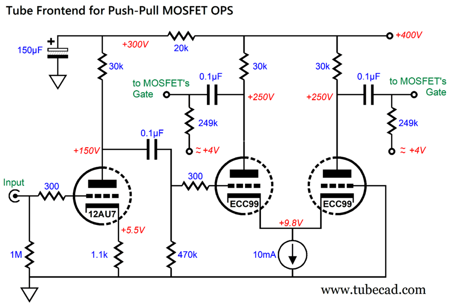
(The RC filter's 100-ohm resistor can be shunted with a 25V zener diode to limit the B+ voltage's collapse under high output. Think of the zener-resistor combo acting as a swinging choke.) How do we drive the MOSFETs to full output? With tubes, of course.
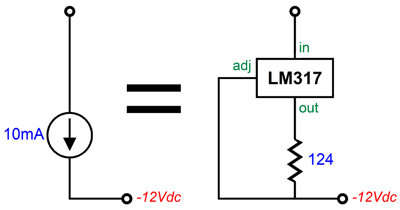
The only thing fancy here is the 10mA constant-current source, which could be made from an LM317 with 124-ohm current-setting resistor.
This input stage requires 1.3Vpk of input signal to deliver ±100Vpk of balanced output, which the electrostatic headphone version needs to deliver ±250Vpk of output. The loudspeaker amplifier version only needs ±80Vpk of balanced output for 4W of output, which 1Vpk of input signal achieves. The constant-current source is a must have feature, as it ensures a balanced output. On the other hand, the constant-current source results in a PSRR of zero from the phase splitter. In other words, a well-filtered or regulated high-voltage power supply is needed.
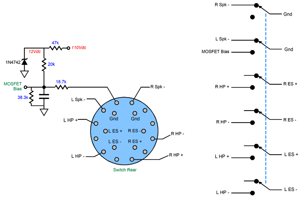
If we wish to combine the electrostatic headphone amplifier with the loudspeaker amplifier, we must devise a way to shift the amount of idle current and select which outputs to connect and disconnect. What complicates things is that either the 8-ohm or the 4-ohm output taps could be in use, and the electrostatic headphones present four stators to be switch in and out. As I see it, a two-position, six-pole rotary switch would work.
Remember, in spite of all the switch contacts (18 of them), the rotary switch only holds two positions: electrostatic headphones or loudspeakers. Turn the knob clockwise and you selected loudspeaker and 7.88V of MOSFET bias voltage; counterclockwise, electrostatic headphones and 4.63V bias voltage. The loudspeaker can be connected to either the 8-ohm or 4-ohm output taps, but their negative terminals are only grounded in the loudspeaker position. The 580Vdc electrostatic headphones bias voltage remains steady, but in the loudspeaker position all four connections to the stators are severed. The primary's DCR of 180 ohms gives each MOSFET a 36-ohm path to ground, which is huge, as most solid-state power amplifiers use emitter or source resistors with values that span from 0.1 to 0.47 ohms. The 36 ohms of DC resistance sees a voltage drop of 3.6V with and idle current of 100mA and 0.54V with 15mA. Since these voltages are relatively so large, we can get away with the simple two-resistor voltage divider to set the idle current, without fearing thermal run-away from the MOSFETs. (The 36 ohms of resistance imposes a great deal of degenerative negative feedback.) By the way, the MOSFETs dissipate 8.64W each with the 100mA idle current and 1.75W with the 15mA idle current. Why not use output tubes in place of the MOSFETs? We could, but the B+ voltage would have to be much higher due to the tube's plate resistance. For example, with a pair of triode-connected 6L6 output tubes, a B+ voltage of 250Vdc would be needed just to get 4W of output. A single 6AS7/6080/6082 twin-triode tube per channel could deliver 4W with a raw power-supply voltage of 120Vdc and a 100-ohm RC filter. Mind you, those four watts are class-A push-pull watts. In addition, the triodes are working as cathode followers, so the output impedance and distortion is low. Actually, I am not sure that the output impedance would be all that low. Let's do the math When we drive the ultra-linear taps, the nominally 5k primary load impedance falls to only 800 ohms. Did you assume 2k ohms, as the ultra-linear taps are at 40% of the primary? An output transformer's winding ratio directly gives up the transformer's voltage and current ratios, but we must take the square of the winding ratio to find the impedance ratio. With an ultra-linear ratio of 40%, the winding ratio drops to 10-to-1, so the impedance ratio falls to 100-to-1, making the 8-ohm load reflect back as an 800-ohm load impedance. Well, to determine the output impedance, we work forwards. The 6AS7 triode's plate resistance (rp) is 280 ohms and its amplification factor (mu) is 2 (this is what the tube manual tells us, which is close enough for quick calculations). The cathode presents an impedance equal to rp/(mu + 1), so when we plug in the 6AS7 values, we get 280/3 or 93 ohms, which we must double, as the two triodes are effectively in series, not in parallel, bringing us to 186 ohms, to which we must add the 72-ohms primary DCR, making a total of 258 ohms. Next, we divide by the winding ratio squared, 10², and get 2.58 ohms, to which we must add the secondary DCR of 0.5 ohms, bringing us to 3.08 ohms. Well, it is lowish. If we applied gobs of negative feedback around the output, we would get a far lower output impedance. Mind you, many exalted tube-based single-ended power amplifier sport higher output impedances. In addition, most tiny computer (desktop) loudspeakers would benefit from a lower damping factor, as they tend to be bass shy. On the other hand, the MOSFETs exhibit at most 1-ohm of source resistance, which would give us an output impedance of 1.24 ohms
What if we desired the full potential power output of 25W into loudspeaker but in class-A? Where did the 25W amount come from? The electrostatic headphones require ±250Vpk of balanced output and the output transformer's winding ratio is 25:1, so the ±500V peak-to-peak voltage swing on the primary becomes ±20Vpk on the secondary's 8-ohm output tap, which equals 25W, as 20²/(2 ·8) = 25. First, a 25W output transformer would be needed. Second, the RC filter would need to be replaced by an LC filter with a low DCR choke. Last, the idle current must be raised to 250mA per MOSFET. This would result in 55W of output stage dissipation, making the output stage's efficiency 45.4%, which aligns with the theoretical maximum of 50% for a class-A output stage. In addition, much more robust MOSFETs would be needed, along with a much larger heatsink and power transformer. Class-A is not cheap. If we retain the smaller AnTek transformer and strive for only 16W of class-A output, the RC filter's resistor should be 62 ohms and at least 12W rated; and the idle current raised to 200mA per MOSFET. John, the AnTek MP-15W50 15W output transformer is rated for 15W, not 16W. Output transformer output ratings are a bit arbitrary. How so? Its output power capability is dependent upon the lowest frequency it is required to pass along to the loudspeaker. The MP-15W50 15W low-frequency cutoff is specified as 10Hz. If we raised the frequency to 20Hz, the transformer could deliver 30W (assuming the transformer's wire does not impose a current limit). If we limited the lowest frequency to 100Hz and we played only music, not steady sinewaves, the transformer might deliver over 150W—as long as the wire didn't reach its fusing-current limit. Okay, all of this has been relatively straightforward, now it's time to fasten our mental seatbelts, as we are moving on to single-ended electrostatic headphone amplification.
Single-Ended ES Headphone Amplifier
with Push-Pull Output Transformer
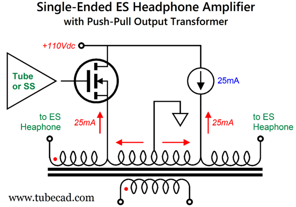
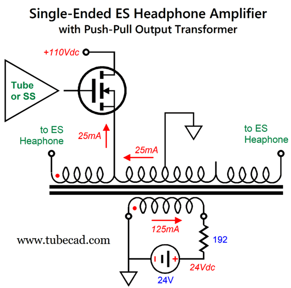
We can press him harder by pointing out that he might not like solid-state, push-pull electrostatic headphone amplifiers, not the solid-state devices or the electrostatic headphones themselves. Think about it, we take an intrinsically push-pull acoustic device, the electrostatic driver, and then drive it with a push-pull amplifier, making for an effectively push-pull² sonic experience. Did you feel the chill? I did. Imagine that you were offered an iced drink on the deck of the Titanic as it heads towards an iceberg. A push-pull output transformer, such as the MP-15W50 15W from AnTek, can be driven single-ended, if and only if, we eliminate the net magnetizing of the core from the unidirectional current flow through the primary. Single-ended output transformers hold big air-gaps, which allow their cores to sustain unidirectional primary current flow without saturating. Push-pull output transformers hold tiny, if any, air-gaps, so they easily saturate with imbalanced DC current flow through the primary. One workaround is to load the other ultra-linear tap with a constant-current source.
Yes, the constant-current source symbol is opposite of the actual current flow from negative to positive. Why? "Conventional" current flow posits the opposite. The word "conventional" stems from the Latin root conventionalis, meaning "pertaining to an agreement." Conventional wisdom says that women, oops I mean womb-encompassing persons, make just as good lumberjacks, cops, football players, bouncers, firefighters, Navy Seals, soldiers, MMA fighters, bodyguards, daredevils as men, oops I mean persons with a… Reality does not have to agree. One obvious problem with "Conventional" current flow is that it makes explaining how a triode functions difficult, as you have to explain how a cold cathode cannot receive—or how the grid stymies—the downpour of electrons from the plate. Okay, back to reality, the NET current flow is zero due to the constant-current source. Thus, the net magnetizing of the transformer's core is also zero. The constant-current source does nothing to drive the electrostatic headphone, as the singe MOSFET must do all the work supplying the needed voltage and current swings into the capacitive load. Yet, both devices must dissipate 2.75W at idle. An alternative arrangement would be to load the secondary with a constant-current source.
Warning, this arrangement works just fine in SPICE simulation, but not in reality, as the SPICE constant-current source model generates current, much in the same way that a battery generates voltage.
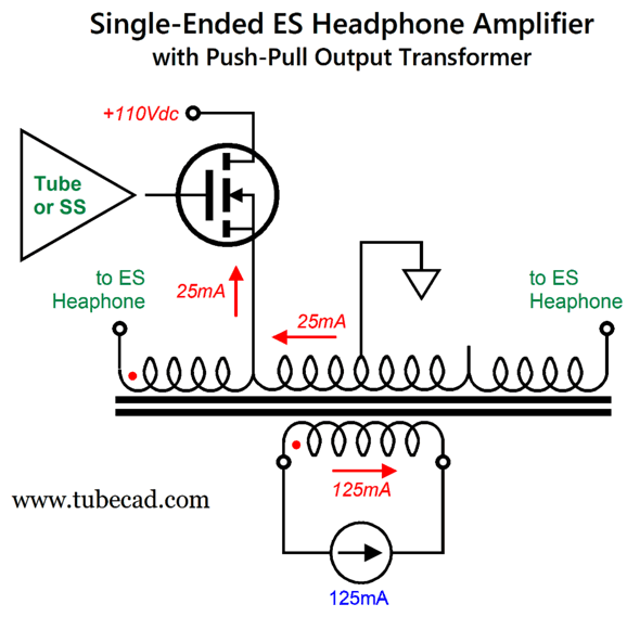
Once again, Reality does not have to agree; in fact, you cannot buy a SPICE constant-current source anywhere. Worse, the constant-current source requires a power supply to power it, resulting in the constant-current source having to dissipate roughly the same amount of heat in the secondary position as it did loading the ultra-linear tap. So what did we gain other than no core saturation? An additional power supply voltage always comes in handy; if nothing else it could power the tube heater elements. By the way, if we add a power supply to the secondary, we do not have to use a constant-current source, as a resistor will do.
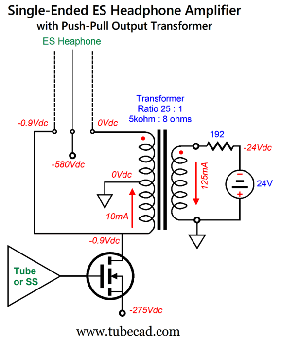
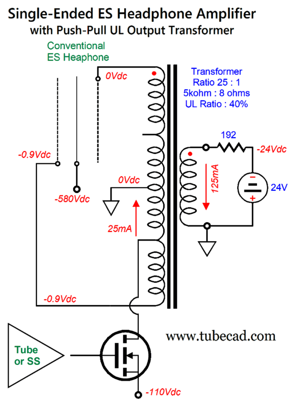
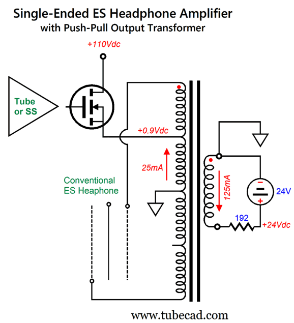
We must make sure that the power-supply voltage is great enough to encompass the peak secondary voltage swing. Assuming a peak-to-peak primary voltage swing of 500V, the secondary will experience a 20V peak voltage swing with transformer's winding ratio of 25:1, as 500V/25 = 20V. By the way, note the transformer's phasing marked by red dots. It is critical that the currents flow in the right directions, otherwise the transformer instantly saturates. The 192-ohm 5W resistor reflects back to the primary as 120k load impedance. As far as the MOSFET is concerned, however, it is working into a 4800-ohm load, as the winding ratio from the ultra-linear tap to the center-tapped to the secondary is 5:1, and 5² x 192 = 4800. By the way, in my own electrostatic headphone amplifier, the stators attach to 60k plate resistors, which in series equal 120k. Divide 500V by 120k of resistance and we get 5mA of peak current flow, which was each output triode's idle current flow in my electrostatic all-tube headphone amplifier. Isn't math great? If we treat the output transformer's primary as an autoformer winding, the center-tap to the ultra-linear tap represents 20% of the winding, making a primary to ultra-linear tap winding ratio of 1:5. In other words, if the ultra-linear tap sees a 100V voltage swing, the entire primary sees a 500V voltage swing. See my Post 618 for more on autoformers offering voltage gain. And in Post 484, we see the inverse, autoformers offering current gain, so its formulas must be inverted. What if the push-pull output transformer does not hold any ultra-linear taps? An excellent question. The answer is that the MOSFET must swing much bigger voltage swings, but idle at a reduced current flow.
In this schematic, the MOSFET no longer is configured as a source follower, but as a grounded-source amplifier. Its idle current has dropped to only 10mA, but its dissipation remains unchanged, as its power-supply voltage is 2.5 times greater, making it a wash. Why only 10mA? The winding ratio has changed from 5:1 to 12.5:1, an increase 2.5 times greater. Put differently, half of the primary has a 2.5 times greater ability to magnetize the core, so only 1/2.5 (40%) as much idle current need flow to match the secondary winding's current flow. As far as the electrostatic headphone's stators are concerned, the peak voltage swing remains the same, 250Vpk, and the peak current swing remains the same, 5mA, as 500Vpk/120k equals 4.16mA peak. So where does the 5mA peak come from? The electrostatic headphone capacitance draws some current at high frequencies as it charges up and discharges rapidly. How do we drive the MOSFET? While it could be done in a hybrid fashion with both tubes and transistors, doing an all-solid-state version is relatively easy.
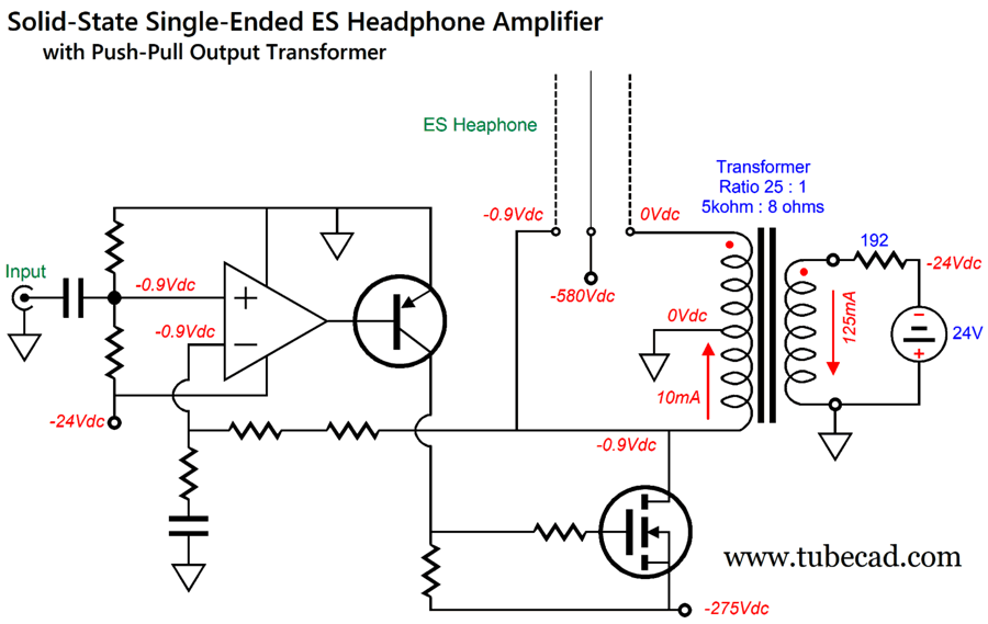
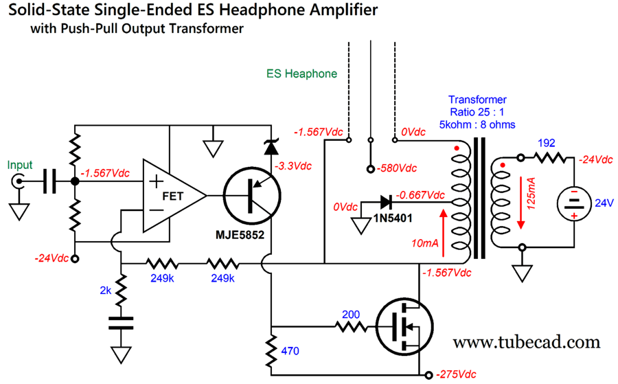
Note the negative bias voltage for the electrostatic headphone. This is the better way to go, not the near universal positive bias voltage, as most dust is negatively charged. Picking the right OpAmp would be the hardest part of the design, as the OpAmp should hold a FET input stage and should be able to accept an input signal equal to or greater than the its positive rail voltage, which in this design is 0Vdc. We can add a rectifier to move the MOSFET's drain voltage down a tad.
Now, the input stage has more breathing room and the output stage can easily drive the PNP transistor's base. The negative-feedback loop sets the MOSFET's idle current flow and lowers the output impedance dramatically. In addition, it establishes a fixed gain. Two negative feedback resistors are used to both limit the maximum voltage drop across each resistor and to lessen voltage-induced resistor distortion, something that seldom comes up in low voltage solid-state designs. On the other hand, if we can find a suitable output transformer with ultra-linear taps, we could reduce the negative power-supply rail voltage to just -110Vdc.
If we desire a tube-based input stage, then the following output stage topology is the way to go:
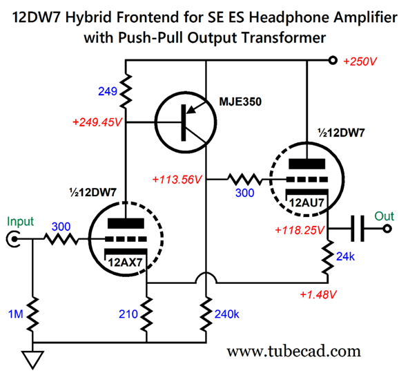
We're back to a source-follower configuration and a positive B+ voltage. One possible tube-based input stage is the following.
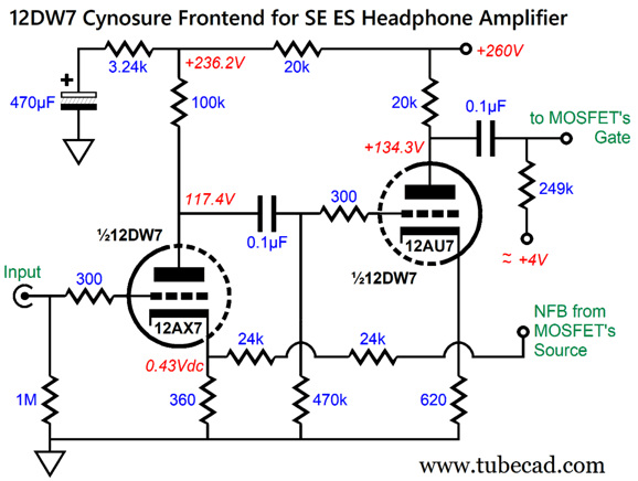
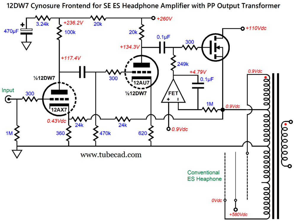
The 12DW7/7247/ECC832 twin-triode tube holds dissimilar triodes, 12AX7 and 12AU7 types. The MJE350 is a 300V PNP transistor that monitors the voltage drop across the 249-ohm plate resistor, and inverts the signal it sees at is base. The 12AU7-based cathode follower idles at high enough current to drive the MOSFET to ±100V voltage swings. A negative-feedback loop extends from the output to the 12AX7's cathode. A pure-tube input stage could be made with cascading grounded-cathode amplifiers.
My signature Cynosure resistor (the 3.24k one) purposely injects just enough power-supply noise to create a noise null at the output. Yes, it is quite counter intuitive, which is why I devised it. See Post 426, Post 536, Post 559, and Post 627. Putting everything together ends up looking like this:
Perhaps, you have wondered why I labeled the electrostatic headphone as being "conventional." Is there an unconventional electrostatic headphone driver?
Indeed there is, just see Post 604 and wait to read my next post.
Music Recommendation:Yello's Touch Yello (Deluxe) Dieter Meier’s signature baritone talking/singing (sprechgesang) is Europe's answer to Leonard Cohen and Lou Reed (and Bill Callahan and late Johnny Cash). Boris Blank is a sonic architect, assembling and structuring an immense audio edifice. The next Yello Album I plan on listening to is Baby, which according to one Reddit post is, "is much more dynamic than Touch is ..... along with being its equal in terms of clarity and sparkle. "
//JRB
Did you enjoy my post? Do you want to see me make it to post 1,000? If so, think about supporting me at Patreon.
AI Summary Reasoning and ApproachTo summarize the key points, I focused on extracting the main technical, conceptual, and practical highlights from the document. The document covers tube amplifier design, transformer characteristics, and innovative approaches to audio engineering, with a mix of personal reflections and music recommendations. Below is a structured summary of the most important points, supported by examples and explanations from the text. Key Points Summary1. Personal and Historical Context
2. Transformer and Amplifier Design Insights
3. Single-Ended Electrostatic Headphone Amplifier Approaches
4. Practical Switching and Biasing
5. Music Recommendation
Conclusion: The document provides a deep dive into transformer selection, amplifier topology, and practical design considerations for both headphone and loudspeaker applications. It emphasizes the flexibility of modern toroidal transformers, the benefits of ultra-linear taps, and the importance of careful biasing and switching in dual-use designs. The technical discussion is complemented by personal anecdotes and music recommendations, making it both informative and engaging.
User Guides for GlassWare Software
For those of you who still have old computers running Windows XP (32-bit) or any other Windows 32-bit OS, I have setup the download availability of my old old standards: Tube CAD, SE Amp CAD, and Audio Gadgets. The downloads are at the GlassWare-Yahoo store and the price is only $9.95 for each program. So many have asked that I had to do it. WARNING: THESE THREE PROGRAMS WILL NOT RUN UNDER VISTA 64-Bit or WINDOWS 7, 8, and 10 if the OS is not 32-bit or if it is a 64-bit OS. I do plan on remaking all of these programs into 64-bit versions, but it will be a huge ordeal, as programming requires vast chunks of noise-free time, something very rare with children running about. Ideally, I would love to come out with versions that run on iPads and Android-OS tablets.
|
I know that some readers wish to avoid Patreon, so here is a PayPal button instead. Thanks. John Broskie
John Gives
Special Thanks to the Special 89 To all my patrons, all 89 of them, thank you all again. I want to especially thank
I am truly stunned and appreciative of their support. In addition I want to thank the following patrons:
All of your support makes a big difference. I would love to arrive at the point where creating my posts was my top priority of the day, not something that I have to steal time from other obligations to do. The more support I get, the higher up these posts move up in deserving attention.
If you have been reading my posts, you know that my lifetime goal is reaching post number one thousand. I have 358 more to go. My second goal was to gather 1,000 patrons. Well, that no longer seems possible to me, so I will shoot for a mighty 100 instead. Thus, I have just 11 patrons to go. Help me get there. Thanks.
New URL of the GlassWare website |
||||













| www.tubecad.com Copyright © 1999-2026 GlassWare All Rights Reserved |