| John Broskie's Guide to Tube Circuit Analysis & Design |
| November 15 2026 | Post Number 650 |
||||
Happy Thanksgiving! Happy Black Friday?
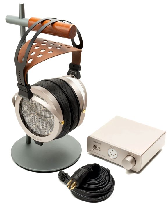
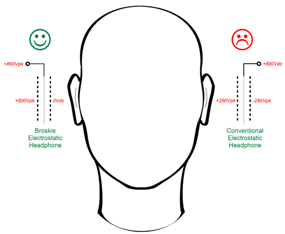
The $650 Hongshu Audio EH-1 & EHA-1 electrostatic headphones and Amp Combo V4 not only comes with its energizer box, but also offers detachable headphone cables. This latter feature would allow me to experiment with my radical electrostatic headphone arrangement, wherein the stators next to my ears are grounded. Each Hongshu headphone holds a three-contact jack, which would give me access to the diaphragm, as it must be partially driven, while the stator furthest from the ear is driven fully. In contrast, with Stax electrostatic headphones the cable isn't detachable.
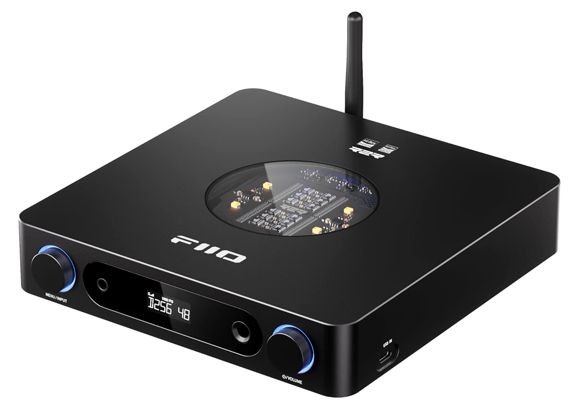
At around half the price, the FiiO K13 R2R Desktop DAC & headphone amplifier has gotten rave reviews. (Do follow the link to the FiiO website, as it shows detail schematic overviews of the DAC and power supply.)
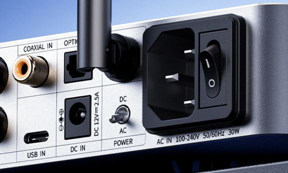
It could replace my current DAC/headphone amplifier. In addition, it sports a switch on the back that allows the user to switch between the internal switch-mode power supply and an external linear 12Vdc power supply.
Nice. Very nice, so much so that it deserves at least a quarter Musk Prize. It wouldn't replace my beloved Schiit DAC, but my DAC/headphone-amplifier from Pro-Ject, the Pre Box S2 Digital, which is getting a bit long in the tooth. In addition, the FiiO K13 offers a set of balanced outputs, something the Pro-Ject Pre Box S2 Digital lacks.
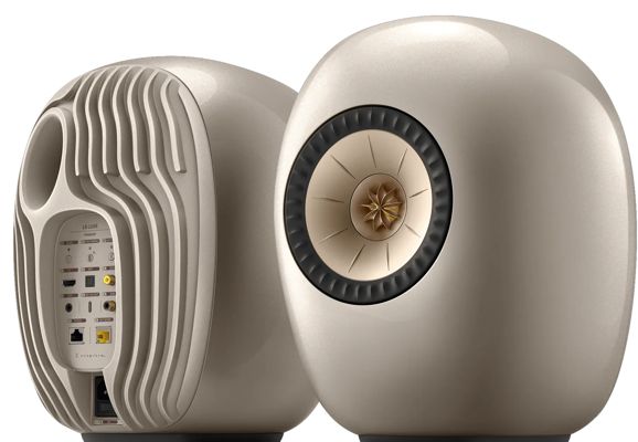
KEF LS LUXE Loudspeaker
Self-powered loudspeakers are nothing new, of course, but this one adds a few embellishments that are new. For example, the egg-smooth enclosure is both eye-catching and sonically valuable; sharp edges on a speaker are like sharp elbows on a coworker or neighbor—something to be avoided. Thank God for 3D printing, freeing us as it does from the right angles preferred by table saws. The two internal power amplifiers are plenty powerful, with a 280W class-D amplifier for the 6.5-inch woofer and a 100W class-AB for the coincident tweeter. (A nice touch that.) Next, we add its motional negative feedback for the woofer, which they label VECO (Velocity Control Technology). Of course, they didn't invent it. In fact, I believe this improvement was patented back in the 1950s; moreover, the 1970s gave us the Philips MFB loudspeaker system. An added feature of this KEF loudspeaker is what it lacks: I do not see any port. (I dislike bass reflex, always have.) Stop the press! I just asked Gemini if it was ported. It is, but with a soft port tube and a flared opening to prevent port-induced resonances. Okay, maybe. Perhaps the inclusion of current-drive with motional feedback tames the otherwise honky bass reflex. All of this is great, but what caught my attention was current drive of the woofer. Current is what makes a speaker driver move. If you look into the equations, you won't find voltage as a variable. Yet, 99.9999% of power amplifiers are voltage-output amplifiers. (Negative-feedback-free tube-based power amplifier often sport output impedance between 2 ohms to 4 ohms, which places them at some midpoint between voltage-output and current-output.) The huge problem with current drive is that the average loudspeaker's impedance plot resembles the outline of the Rocky Mountains or a roller-coaster. Not good. Combine current-drive with motional feedback and you have a winning design. I have yet to hear the LS LUXE loudspeakers, but I have heard their baby brother, the $1500 the pair LSX II loudspeakers. Quite impressive.
Powered 3-Way Loudspeaker
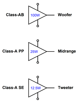
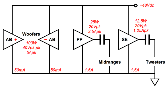
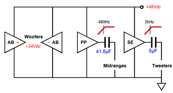
Having three power amplifiers run off of a 48Vdc B+ voltage seems to imply three 25W amplifiers, but that assumes an 8-ohm load throughout and conventional push-pull output stages. If we used a bridged-amplifier topology for the woofer, then we would get 100W with an 8-ohm load; in contrast, with a class-A, push-pull power amplifier and an 8-ohm load midrange driver, 25W; with a single-ended amplifier and 16-ohm tweeter, 12.5W. All of them running off the 48Vdc.
The 100W class-AB amplifier could be replaced by a class-D amplifier configured in TBTL arrangement. (Tied Bridge-Tied Load configuration—also commonly known as PBTL, i.e. Parallel Bridge-Tied Load.) Of course, any class-A amplifier is going to have a high idle current and dissipate a lot of heat, so massive heatsinks will be needed. Perhaps all the electronics could be housed a squat square enclosure resting under the loudspeaker. Or, the sides of the speaker enclosure could be made from black-enamel painted aluminum sheet. Surface area is all important in a heatsink.
The current-flow division between amplifiers is interesting. Note the same idle current for the two class-A amplifiers (1.5A) and the trivial idle current flow for the class-AB power amplifiers. Further note that the class-AB amplifiers deliver hundredfold bigger peak current flows than their idle current, 5A peak versus 50mA. In contrast, the push-pull class-A amplifier delivers twice its idle current into the loudspeaker, while the single-ended class-A output stage delivers a peak output current swing equal to its idle current. Well, does that not mean that the idle current of 1.5A should have been 1.25A? Yes it does, but I wanted to build in some current headroom for speaker drivers that dip below their nominal impedance. Class-A means current. All class-AB run in pure class-A, if the load impedance is high enough not to exceed the amplifier's class-A window of current conduction. The two woofers will see 24Vdc at both class-AB amplifiers' outputs; thus no net DC offset. No voltage difference across the voicecoil, no movement. The midrange drivers and tweeters must be capacitor coupled due to the monopolar power supply. Well, why not put these coupling capacitors to further use by making them part of the crossover?
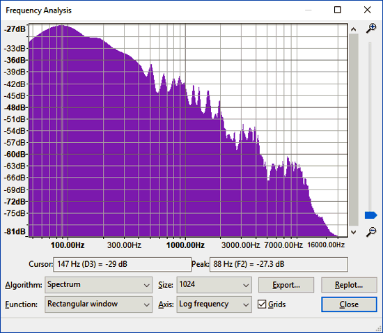
These capacitor values set the crossover frequencies of 480Hz and 2kHz. By the way, we can get away with the declining output power with higher frequencies due to most music exhibiting a steep roll off of frequencies above about 300Hz, depending on the music.
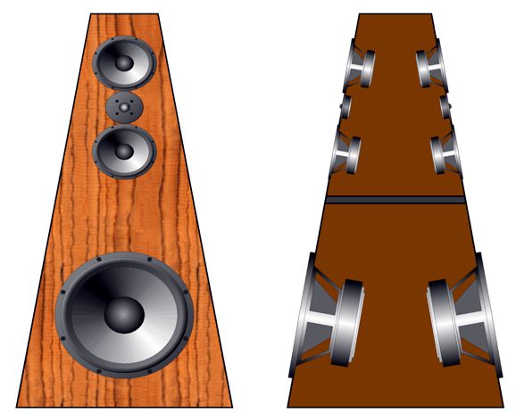
Note that it peaks at about 90Hz and at 900Hz the magnitude is down about 12dB, which means one quarter the signal amplitude and 16 times less power delivery. Tweeters do not see much signal above their crossover frequency, but they do see a lot of potential power below the crossover frequency. This is why cascading 3rd-order high-pass filters, in terms of tweeter protection, are so desirable. In fact, if I cannot have a 1st-order crossover or an asymmetrical phase-flat crossover, the 3rd-order Butterworth is to my ears far more preferable than 2nd-order Linkwitz-Riley, which always sounds a bit off to me, which leads me to prefer the 4th-order Linkwitz-Riley alignment over the 2nd-order—but only when an active crossover is used. Imagine a tall, truncated pyramid loudspeaker with drivers on both the front and back, making the loudspeaker a bipole (not dipole, as all the drivers are in phase).
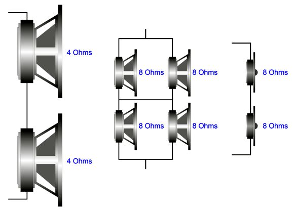
The two woofers could be either 8-inch or 10-inch; the four midrange drivers, 4 to 6 inches; and the tweeters, 1-inch domes or fancier. The non-parallel sides help squelch standing waves and resonances within the enclosure. All the drivers, save for the two 4-ohm woofers, are 8-ohm types.
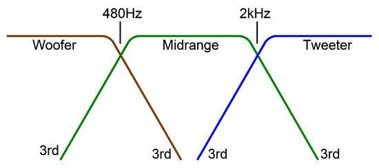
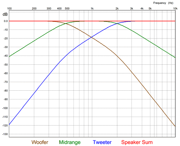
The active crossover that most audiophiles would assume delivers the following amplitude plots.
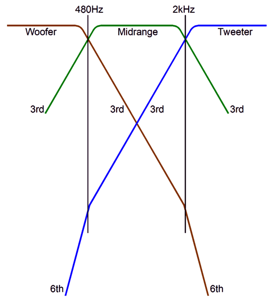
It's both textbook and common practice, but it does not yield a flat frequency response. What is needed is a cascading of the low-pass and high-pass filters.
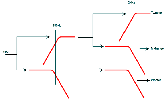
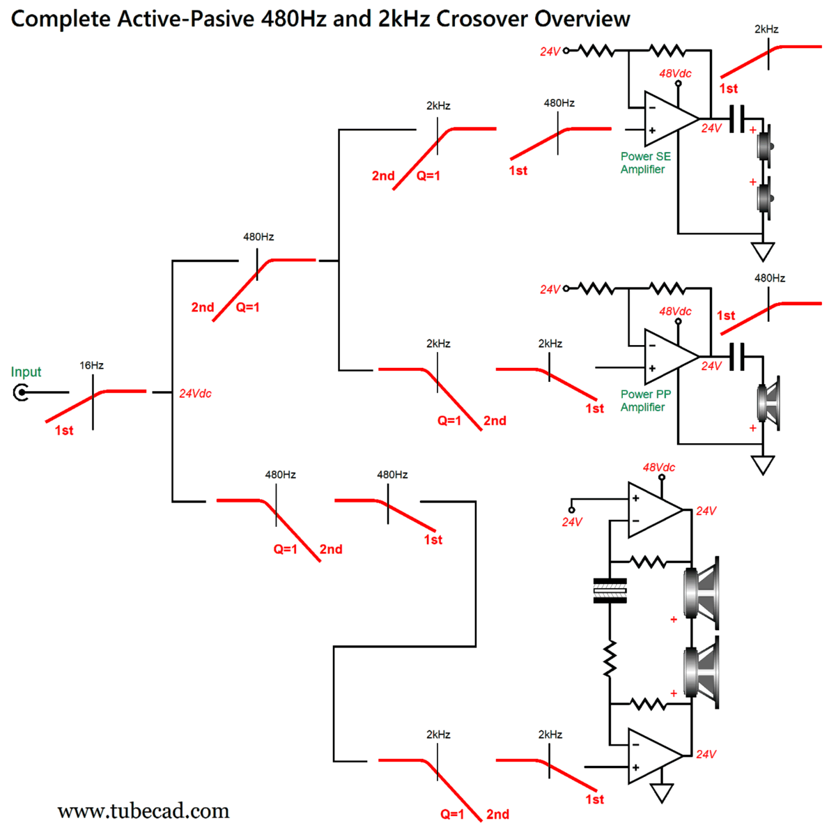
Above the 480Hz crossover frequency, the woofer sees a 3rd-order cutoff slope, up until the second crossover frequency is encountered, as the slope increases to 6th-order thereafter. Likewise, the tweeter starts at 3rd-order cutoff and ends at 6th-order. Not only will this sum to frequency flat, it gets the turgid woofer out of the way and offers far greater tweeter protection. Here is the crossover's flow chart.
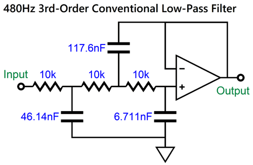
Well, it's a conceptual flow chart. The reality is that we must include the 1st-order high-pass filters imposed upon the midrange driver and the tweeter by the output coupling capacitors and something most didn't know existed. All crossovers require tight-tolerance capacitors. Passive crossovers also require tight-tolerance inductors. Fortunately, active filters have done away with the need for inductors, having replaced them with resistors and positive feedback from an OpAmp. The big problem is that, today with analog radios and TVs no longer being made and with the world having gone digital, the need for tight-tolerance capacitors has lessened to point that these capacitors are both expensive and difficult to source. For example, your active crossover might specify 0.01838µF and 0.01378µF capacitors, but good luck finding 1% capacitors in those values. The clever electrical engineering workaround is to use a variation on the Sallen-Key active filter that uses the same capacitor value throughout. Let's start with a conventional Sallen-Key active high-pass filter with a Butterworth alignment.
I am surprised that the capacitor values are not as bad as I expected, as 47nF, 120nF, and 6.8nF are close to these values; in fact, these readily available capacitor values would only shift the crossover frequency down to about 470Hz. The problem is that we cannot bank on luck. The smart workaround is the following:
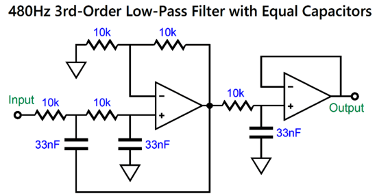
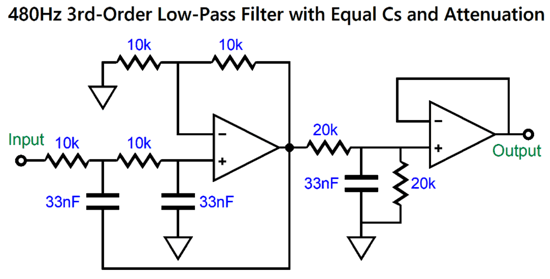
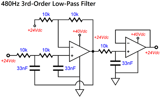
Two OpAmps are needed, but that is a small price to pay for getting the same capacitor value. It turns out that 33nF is readily available 1% tolerance. The formulas for the filter are simple enough: C = 159155/F/R and R = 159155/F/C and F = 159155/R/C The capacitor value is in µF. One potential liability is that this low-pass filter also delivers a gain of 6dB (1:2 or 2X). We can add an input attenuator or do the following to erase the gain.
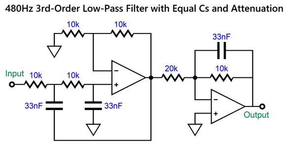
The two 20k resistors are effectively in parallel, making a 10k resistance. An alternative way to introduce attenuation is to use an inverting low-pass filter at the end.
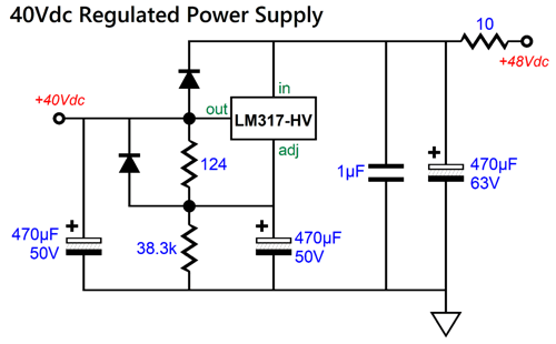
The 20k resistor forces a -6dB (1:0.5 or V/2) attenuation. If we replace the 20k resistor with a 40k resistor, we get -12dB of attenuation. What complicates matters is the monopolar power supply of 48Vdc, while most OpAmps like lower differential power-supply voltages, typically ±12Vdc to ±22Vdc, with latter making a differential voltage of 44V. We could place voltage-dropping zeners in series with the OpAmps, but that would lead to noise (and possibly flaky performance). The better solution is to use a voltage regulator.
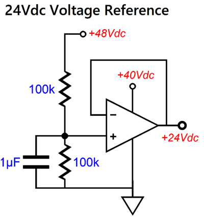
As the LM317-HV can withstand an input voltage of 56Vdc, the 48Vdc is safe enough as a B+ voltage. The 10-ohm resistor and 470µF capacitor define an RC filter with a low-pass-filter frequency of 34Hz. This pre-filtering greatly improves the regulator's PSRR. The next problem is that the power amplifiers must situate their outputs at half the B+ voltage, in this case 24Vdc. Thus, what we need is a 24V voltage reference.
Actually, this is not a true voltage reference, as it merely halves the B+ voltage, which is a feature in this application, as a higher or lower B+ voltage could still be used. The 24Vdc output will be treated as a faux ground in the crossover.
Here, we see the 24V entering and exiting the low-pass filter. The high-pass filter gets a slightly different treatment.
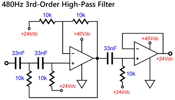
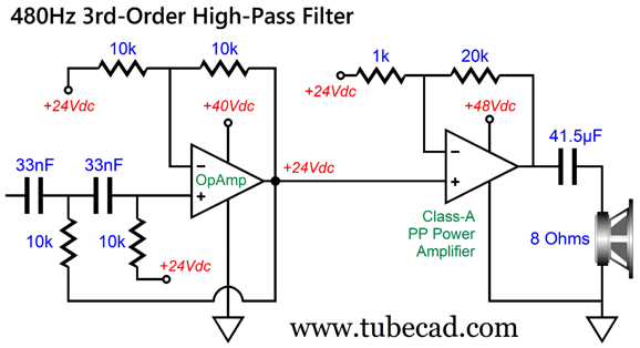
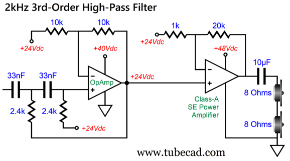
All three 10k resistors terminate into the 24V reference voltage, not ground. Since the class-A, push-pull power amplifier that drives the midrange drivers is capacitor coupled at its output, and since this coupling capacitor is part of the crossover design, we can omit the second OpAmp and the third 33nF capacitor.
I like having the coupling capacitor at the output, as it offers additional safety for the midrange drivers, something a DC connection to the output wouldn't offer. The downside is that a 41.5µF high-quality film capacitor would be neither small nor cheap. The 2kHz, 3rd-order, high-pass filter for the tweeter looks like this:
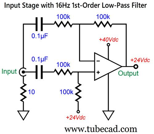
All these active filters assume a low-impedance input signal referenced to 24Vdc. This is how we achieve these goals and provide some hum avoidance.
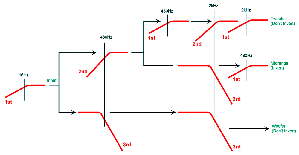
This is a unity-gain differential amplifier that ignores common-mode noise and imposes a 16Hz high-pass filter on the incoming signal. Long interconnects are hum magnets. In theory, the 10-ohm resistor is not needed, but it probably will be needed. The 0.1µF capacitor's termination on the RCA jack is essential, for a complicated reason which I will not go into now. Trust me; do it. The alternative is to use an input isolation transformer, which will banish the hum, but they are costly. It's now time to reevaluate our filter flowchart.
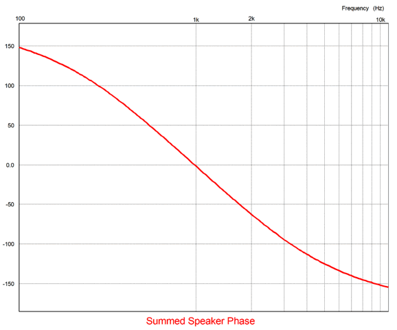
Note that the midrange driver must be in anti-phase with the woofer and tweeter. With the arrangement shown above, we get the following phase plot for the loudspeaker sum of all drivers.
Note that I didn't include the input 16Hz 1st-order high-pass filter from the differential input stage in this graph or in the following frequency response graph.
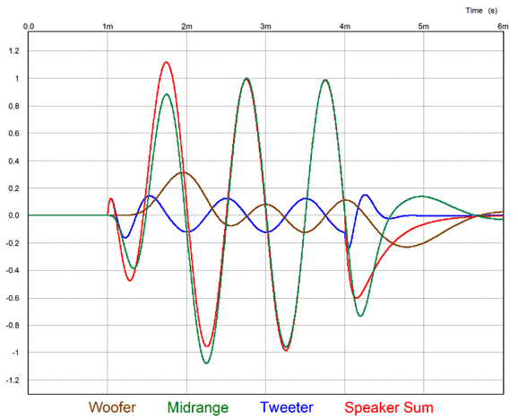
The three-cycle 1kHz tone burst graph shows that the 3rd-order crossover is not transient-perfect (phase-flat), but I have seen much worse.
Now, we must make a finer-resolution crossover flowchart.
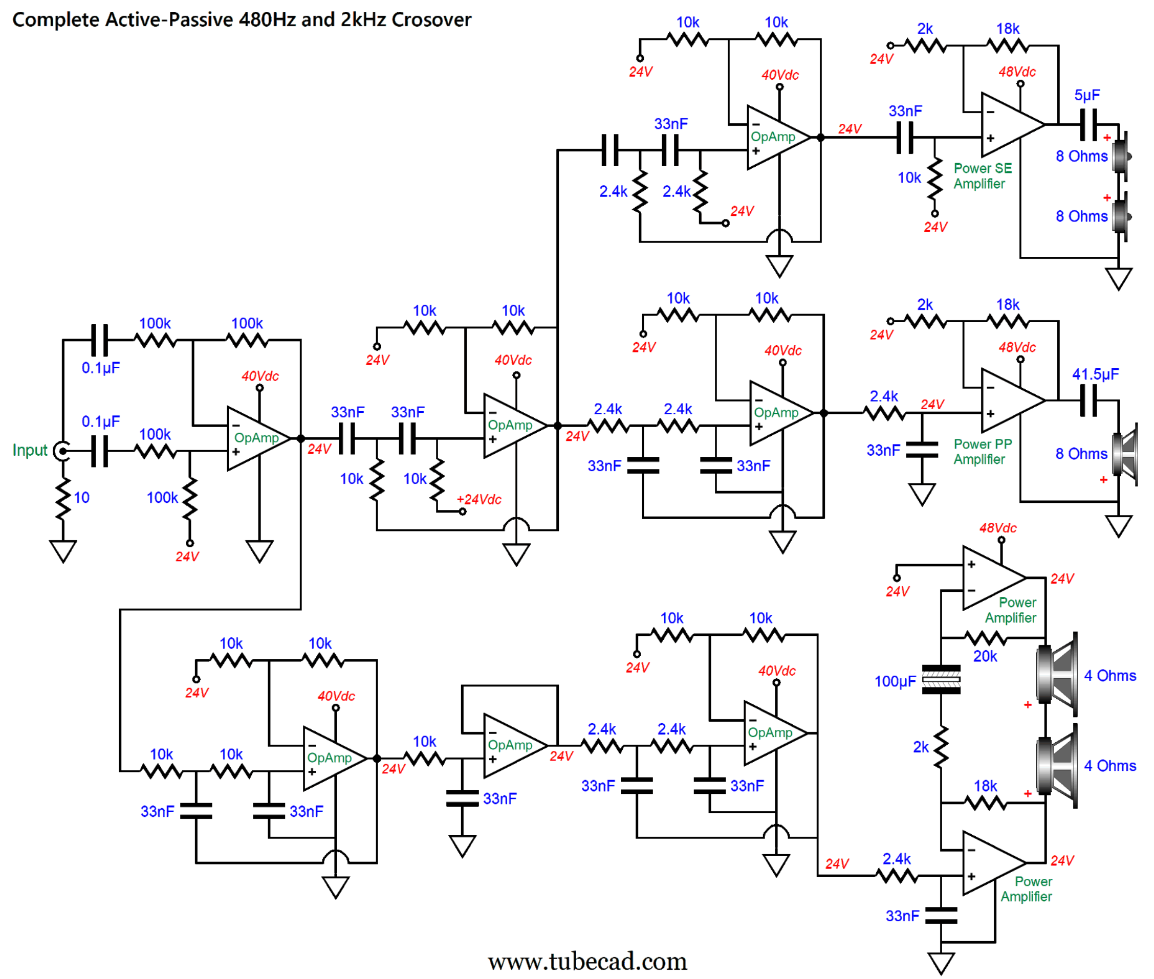
Note how the woofers see a bridge amplifier and 24Vdc at each end. It may look like the woofers are wire in anti-phase, but they are not, as the top amplifier in the bridge arrangement is inverting. An interesting question is, How do we adjust for differing SPL/W drivers? We assume that the tweeter will offer the highest SPL at 1M and 2.828Vrms and that the woofer will offer the least SPL. Note that the two tweeters are in series, so each will incur a -6dB diminishment in SPL. For example, a normally 94dB tweeter will now put out 88dB. The four midrange drivers are in series-parallel, so each driver will be down -6dB, but as we have two drivers on the front and two in the back of the speaker enclosure, we gain 6dB due to the doubled radiating surface area; in other words, a wash, so the specified SPL is the effective SPL. The woofer SPL can be brought up to the midrange driver and tweeter SPL level by tweaking the bridge amplifier gain. Now come the onerous part: drawing the complete schematic.
Yes, it is indeed a beauty. No doubt suitable for framing. Note that all the power amplifiers see the input signal—after passing through cascading filters—four times greater in magnitude. In other words, 1Vpk go in and the amplifiers see 4Vpk. This explains why all the amplifiers exhibit a gain of only 20dB (1:10 or 10X). Even the bridge amplifier arrangement effectively delivers a gain of 10X to each woofer.
Woofer Class-AB Amplifier
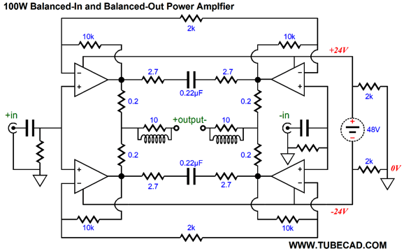
For those too lazy to follow the link to that post, here is the bridge amplifier based on the LM3886 (four of them) from that post.
Much of this can be lifted and used to drive the two woofers.
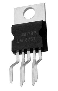
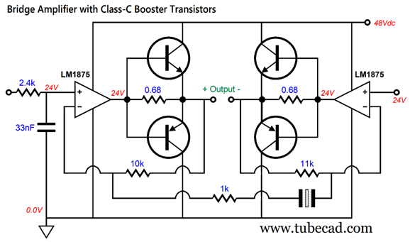
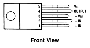
An alternative idea I had was that we could get away with using two 5-pin power amplifier ICs, such as the OPA544 and the LM1875, with current-booster transistors.
All four power transistors are turned off at idle and only turn on when the current flow through the 0.68-ohm resistors exceeds about 0.9A. In other words, the IC power amplifiers solely drive the woofers up to about 3.5Vpk, thereafter the transistors turn on and supply the needed current flow into the 4-ohm loads. Effectively the IC power amplifiers are current limited to about 1A, which greatly lowers their heat dissipation. The booster transistors run in class-C, which also lowers their dissipation. Think of it as hardcore class-B. By the way, I would never think of running a loudspeaker fullrange with this bridge amplifier. Why not? Switching glitches at high-frequencies.
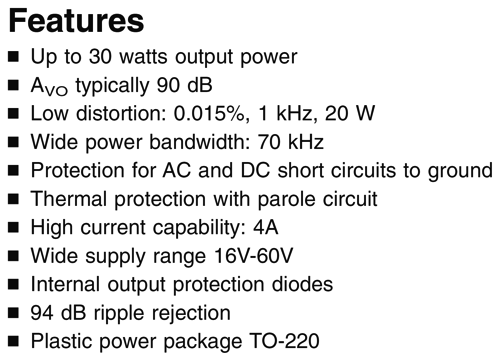
As a young man I built a boosted headphone amplifier long ago, after I saw the topology in a Texas Instrument datasheet. I saw it as a godsend, as my IC-based headphone was woefully under powered. Adding the transistors did supercharge the power delivery, but at the cost of an irritating high-frequency sonic signature. The bass output, however, was quite good. In other words, with two cascading 3rd-order low-pass filters and high-frequency-limited woofers, this topology's potential high-frequency failings are not an issue. Mind you, the OpAmps I used were quite wimpy back then, so they had a hard time driving the transistors. In contrast, the LM1875 was designed to drive loudspeakers. At full output, ±20Vpk, the LM1875 thinks it is driving a 20-ohm load, as 20V/1A equals 20 ohms. The pair of output transistors thinks it is driving a 5-ohm loudspeaker, as 20V/4A equals 5 ohms. At peak output power, each transistor dissipates only 12W. In other words, not much.
The advantage the OPA544 offers over the LM1875 is that the OPA544 is unity-gain stable, which allows us to lower its gain without worrying. The advantage the LM1875 offers over the OPA544 is that the LM1875 requires less voltage headroom, if I remember correctly. In other words, it can swing bigger output voltages with the same power supply voltage. The more interesting project is the tweeter's single-ended power amplifier.
Tweeter's Single-Ended Amplifier
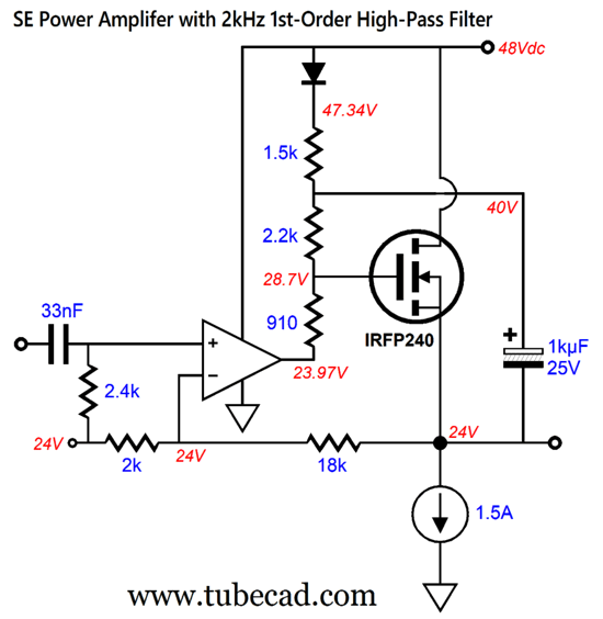
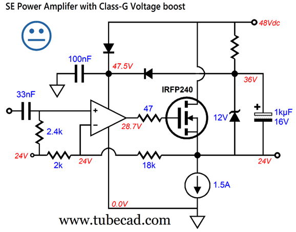
The bootstrap 1kµF capacitor rides along with the output signal, so at +20Vpk, the top of the capacitor will be at +60Vpk, which extends the OpAmp's output voltage swing enough to drive the MOSFET to full output. (The 910-ohm resistor also acts like a gate-stopper resistor.) The diode allows the capacitor to swing above the B+ voltage without discharging. Another idea I had was to apply some Class-G mojo to the circuit.
At idle and with low output voltage swings, the OpAmp gets its B+ voltage from the 48Vdc power supply. With large positive output voltage swing, the OpAmp gets it B+ voltage from the 1kµF capacitor. With the amplifier's +20Vpk voltage swing, the top of the capacitor will be at +56Vpk. The uncommitted face icon is there due to my worry about high-frequency switching glitches, which explains why the 100nF capacitor is there. Yet another idea I had was that we could make the class-A single-ended amplifier a two-stage affair, with high-voltage, rail-to-rail OpAmp delivering the needed signal gain and a floating unity-gain OpAmp driving the output MOSFET.
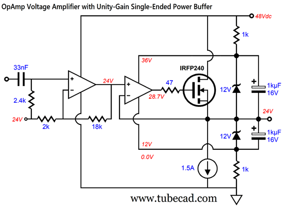
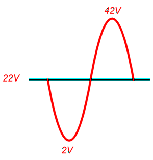
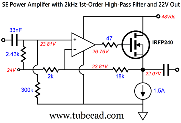
Of course, dual-amplifier OpAmps could not be used, but a single-amplifier, low-voltage, high-current OpAmp could be used to drive the N-channel MOSFET's gate. It's always good to stop and ask is this trip really necessary. Is it? There are three limitations to maximum output voltage swing, the B+ voltage the constant-current source's minimum voltage overhead, and the MOSFET's 5V gate-to-source voltage. (This assumes a rail-to-Rail output OpAmp.) What if we lower the output idle voltage to 22 volts?
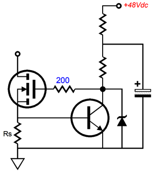
The peak output voltage swing is now 42V, not 44V, which leaves 6 volts of headroom for the OpAmp and MOSFET and 2 volts of headroom for the constant-current source. Will this work? Perhaps. The constant-current source is not a problem, as the following circuit topology should do it.
The NPN transistor needs only a base voltage of about 0.6V to conduct. The OpAmp is a bigger problem. The ADA4522-1's datasheet boasts of only a 1V dropout voltage at 14mA of current flow. The next problem is how do we get a 22Vdc voltage reference? Here is how.
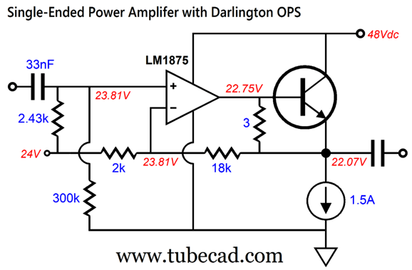
The 2.43K and 300k resistors in parallel equal 2.41k. In series, they define a two-resistor voltage divider that drops the 24Vdc down to 23.81V. This got me thinking that an NPN transistor might be the better choice, which in turn got me thinking that the LM1875 power amplifier could replace the high-voltage OpAmp.
The LM1875 no longer runs in class-AB, as its internal NPN transistor draws close to 227mA, and it never turns off, while its internal PNP transistor never turns on. This is a single-ended amplifier—all of it. The constant-current source not only provides a high-impedance load, but also delivers auto-bias functionality. In fact, the constant-current source performs the same functions as the pull-down resistor we add to OpAmps to force them into single-ended operation.
The NPN transistor will get plenty hot, as it must dissipate around 33W at idle. In other words, a big heatsink is needed. If two NPN transistors are used in parallel, then each should encounter a 0.1-ohm emitter resistor, so as to prevent current hogging. A constant-current source loaded single-ended output stage is only 25% efficient after all, and 12.5W output power output with 66W of idle dissipation equals only 19% efficient. The remaining issue is the question whether the LM1875 is still high-frequency stable with only a gain of 20dB (1:10 or 10X). Its datasheet informs us:
In other words, the input signal might have to be attenuated and the LM1875's gain increased. What about the class-A, push-pull power amplifier for the midrange drivers? That will have to wait for my next post, as my fingers are giving out from so much typing (approaching 4,000 words). So what was this exposition? Was it a complete project plan? Not really, as it was more of an exploration of possibilities, an attempt to think outside the loudspeaker box. A bipole loudspeaker with a truncated pyramidal enclosure holding three power amplifier of differing amplifier classifications and an elaborate active crossover all fall outside the typical box speaker.
Music Recommendation:
Yello, Time Lab
//JRB
Did you enjoy my post? Do you want to see me make it to post 1,000? If so, think about supporting me at Patreon.
Adobe AI Summary: Here are the main takeaways from the document: Personal Updates and Audio Product Reflections
Audio Equipment Analysis
Loudspeaker Design Concepts
Implementation Details and Schematic Innovations
Overarching Theme
Music Recommendation
This summary captures both the technical audio design insights and the personal reflections presented throughout the document.
|
I know that some readers wish to avoid Patreon, so here is a PayPal button instead. Thanks. John Broskie
John Gives
Special Thanks to the Special 95! To all my patrons, all 95 of them, thank you all again. I want to especially thank
I am truly stunned and appreciative of their support. In addition I want to thank the following patrons:
All of your support makes a big difference. I would love to arrive at the point where creating my posts was my top priority of the day, not something that I have to steal time from other obligations to do. The more support I get, the higher up these posts move up in deserving attention.
If you have been reading my posts, you know that my lifetime goal is reaching post number one thousand. I have 351 more to go. My second goal was to gather 1,000 patrons. Well, that no longer seems possible to me, so I will shoot for a mighty 100 instead. Thus, I have just 5 patrons to go. Help me get there. Thanks.
New URL of the GlassWare Store website |
||||








| www.tubecad.com Copyright © 1999-2026 GlassWare All Rights Reserved |