|
October |
|
Page 6 |
|
Copyright © 2003 John Broskie All Rights Reserved |
|
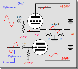
So, what have we gained from moving the reference to the other side? Other than confusing many, nothing, absolutely nothing. The gain, Zo, PSRR, distortion, and bandwidth remain unchanged, in spite of the power supply floating up and down equally with the output signal. (Of course, there might be clever input and driver stage tricks that could be implemented with this variation that would not be possible with the generic version, with its fixed power supply, but that is not relevant to how the basic output stage topology functions.) Now, let’s move the reference point again. Continuing our clockwise movement, this time to the center of the output, via a two-resistor voltage divider. |
|
Notice, however, that the drive signals for bottom and top triodes are now equal in magnitude. In both previous variations, we had favored one triode over the other, but not here, as each triode shares the same claim over the output stage’s reference. (The sad fact is that many tube practitioners think that this new topology and its functioning are identical to the original totem-pole topology. Why otherwise would they be so oblivious to the two different signal reference points in the original totem-pole amplifier, as evidenced by their delivering the same grid voltage swing to the top and bottom tubes?) Amazing what we can do with two resistors and re-soldering one wire. Now let’s rearrange some other circuit elements. The triode, which is a modified diode at heart, can only conduct current when its cathode is less positive than its plate.Thus, we cannot invert the triode’s relation to the power supply, (well, we could, but the triode would cease to conduct) but we can swap the positions of the bottom triode and bottom power supply. |
|
Reordered one-tube-on-top-of-the-other push-pull class-AB amplifier with the signal reference shifted to the center of the output and the power supply is left floating, i.e. it is not directly connected to ground |
|
Your Ad Here Ad space is available for the next issue of the Tube CAD Journal |
|
This new variation above will probably cause a lot of head scratching, as it seems only slightly different from the original, but very, very wrong, like a tennis match on top of a teeter-totter. The two-resistor voltage divider splits the output signal and fixes ground at that point. The power supply is left floating and it moves up and down with the output signal, although by only half as much as in the previous variation. Once again, both triodes function in the signal degeneration mode (ala a cathode follower). Once again, the gain, PSRR, distortion, and bandwidth remain unchanged. (Truly observant readers will have realized that output impedance did not make the list of shared attributes this time. More on that later.) |