|
More ð |
|
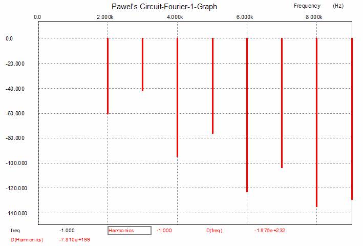
Fourier analysis of Pawel’s first circuit: a DC headphones amplifier (0.32 volts at 1kHz into 32 ohms) in B2 Spice A/D |
|
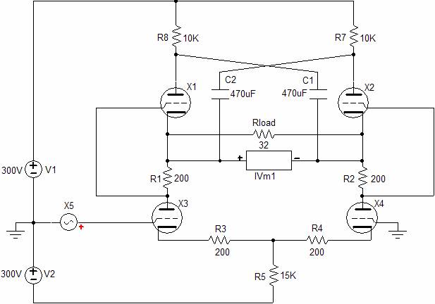
Well, how do improve the performance in terms of gain and output impedance? Different tubes or more tubes? Or how about an output transformer? Any of these would help, but each has its own problem area. For example, using a higher mu triode (12AX7 or a 5751, say) for the bottom differential amplifier would increase the gain, but it would also severely lower the idle current into the top triodes (a workaround would be to add resistors from the top cathode to ground). Doubling the total number of triodes would halve the output impedance, but only halve an already extremely high output impedance (3k relative to 32 ohms is extremely high by anyone’s standards). Well then, how about an output transformer? Output transformers are electrical levers that magnify the load impedance, while reducing the output voltage swing and increasing output current swing. So while we would see a greatly reduced output impedance (3k divided by the wing ratio squared), the voltage gain would also fall by the winding ratio of the transformer. (Actually, in this case, where the load impedance is so grossly mismatched to the amplifier, the gain reduction would not be so great, as the amplifier could realize more gain before it was reduced by the transformer.) Additionally, output transformers bring the issue of airgaps; if a non-airgapped output transformer sees a net DC magnetizing current, it saturates, which in this circuit, it could easily, as absolute DC balance would be difficult to guarantee. So a coupling capacitor for the output transformer’s primary might be the better way to go, although in violation of Pawel’s first goal. If we pull back a few hundred feet and look at the circuit, we that the 32-ohm load is terminates into some very spongy components: the triode’s rp and a 10k resistor. If we could shorten the current path with low impedance devices, the situation would improve greatly. In the schematic below, we see a circlotron transformation of Pawel’s circuit. (Once again the poor naming convention or lack of a naming convention arises. The actual Circlotron circuit used more tricks than two power supplies. A better name for this sort of topology might be “Figure Eight,” as the current circle has been twisted or folded on itself, like a rubber band made into a figure eight. Or, perhaps, “Horizontal” would be a better name, as it would find a compliment in “Vertical,” what we now call “Totem Pole.” Here is a set of questions for the more accomplished tube practitioners: given a horizontal and a vertical amplifier with the same output tubes and same power supply wallop, i.e. the horizontal amplifier holds two 100V power supplies, the vertical, one 200V bipolar power supply, how will they differ in gain, output impedance, harmonic distortion, maximum voltage swing, and maximum current swing?) |
|
Note the increased power supply voltages and the addition of two resistors (R8, R7) and two capacitors (C1, C2). These added parts allow the top triode’s cathodes and plates to be tightly coupled in AC terms, while preserving their DC independence. To see how this works, imagine throwing a 2-volt battery across the outputs. One cathode would go up 1 volt, while the other would go down 1 volt; one plate would go up 1 volt, while the other would go down 1 volt. Since the added capacitors do not look like coupling capacitors, looking more like power supply capacitors, are they in the signal path? As so much of audio is psychological, they probably will fly below most audiophiles’ radar, while in fact they are 100% in the signal path. (I once knew this tubeaholic who refused to use Radio Shack 6FQ7s, even though they where relabeled Amperex tubes, because he did not want his system’s sound contaminated by a “Realistic” product.) With the added parts, the output impedance falls to 1k (three times better) and the gain climbs to 0.263 (twice as good) and the distortion also takes a dive down to 0.1% (one tenth it previous value). Not bad, but not great enough, given the 32-ohm load; and the issue of safety remains. The high output impedance is a only nuisance, but the safety hazard is the pressing danger. How can this amplifier be made safe? If the added capacitors were replaced with four capacitors, one capacitor replaced with two in series, then we could attach the load at the capacitor’s midpoints, which could be referenced to ground via two resistors. Thus the circuit’s functionality would remain, while our ears’ safety is ensured. Following is the schematic of the amplifier improved and made safe. |
|
Pawel’s DC headphones amplifier made circular Download B2 Spice circuit |
|
N |
|
Lethal voltage at output. Not recommended |
|
www.tubecad.com Copyright © 2003 GlassWare All Rights Reserved |