| This happens because the amplifier's low output impedance overwhelms the grid's freedom to move; in contrast, if a current source feeds the input, the full feedback mechanism is restored. The key point is that the impedance looking into the converter must be high, so as to give the grid the freedom of movement required to convert the incoming current into voltage. Fortunately, designing high output impedance tube circuits is an easy task. Pentodes naturally have very high output impedances, which suit driving an I-to-V converter nicely. And using a large valued cathode resistor in a triode based grounded cathode amplifier makes the output impedance climb. The math is simple: Zo = rp + (mu + 1)Rk For example, a 6SN7 with a 20k cathode resistor will have an effective plate impedance of 428k; a 12AX7 with a 50k cathode resistor, 5 meg.
If the stipulation that the input be fed by a high impedance source is met, then math is straightforward. The conversion ratio is roughly given by: Ratio ≈ IRfb / (1 - 1/[gain +1]) A tube I-to-V converter's output impedance is the same as it was with only the coupling capacitor joining plate to grid. This makes sense, as the series resistor does attenuate the plate voltage variations, for the resistor is not part of a voltage divider. Infinity divided by the sum of infinity plus the series resistor, Rfb, still equals unity. Thus the output impedance for a triode based I-to-V converter is a given roughly by: Zo ≈ rp / (mu +1) And for a pentode based I-to-V converter is roughly given by: Zo ≈ 1 / Gm The input impedance for either tube type is roughly given by: Zin ≈ (Zo + Rfb) / (gain +1) In all of the above formulas, gain refers to the open-loop gain of the circuit. Why all the "roughly" and imprecision? The practice of simplifying formulas in textbooks has irked me greatly, as I want all the insight I can get into tube circuits. Yet, I see its use. If the formula exceeds our ability to quickly see into it, we do not try to do so. So, now that we have had a good look, let's move on.
|
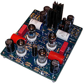
High-quality, double-sided, extra thick, 2-oz traces, plated-through holes, dual sets of resistor pads and pads for two coupling capacitors. Stereo and mono, octal and 9-pin printed circuit boards available. Designed by John Broskie & Made in USA  Aikido PCBs for as little as $24 http://glass-ware.stores.yahoo.net/
|
|
| www.tubecad.com Copyright © 2001 GlassWare All Rights Reserved |