| John Broskie's Guide to Tube Circuit Analysis & Design |
26 July 2023 Post Number 585
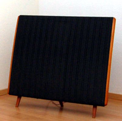
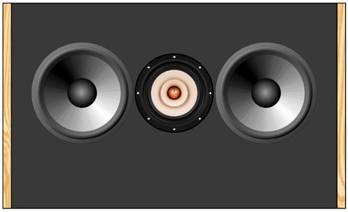
Quad Envy Well I, too, long to build a Quad 57 flavored and inspired loudspeaker, but using dynamic drivers, like the DQ10. Unlike the DQ10, however, which held many drivers and many crossover frequencies, I want to stick to the Quad's single 1st-order 500Hz crossover. Imagine two low-frequency woofers flanking a fullrange driver.
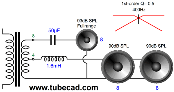
The fullrange operates as a dipole, while the two woofers get sealed enclosures that raise the cabinet resonances up to the fullrange driver's free-air resonance, say around 50Hz. The problem that arises is that an 8-ohm fullrange needs to mate with two either 16-ohm or 4-ohm woofers, so as to make a final 8-ohm loudspeaker load impedance. Well, 16-ohm woofers are rare, while 4-ohm woofers are common; thus, we choose 4-ohm woofers. A wrinkle develops, however, as 4-ohm driver SPL ratings comes in two forms: SPL at 1W of power at 1 meter versus SPL at 2.8Vrms at 1 meter. The second method results in 2W of power delivery, which further results in a +3dB increase in SPL compared to the 1W method of testing. Assuming that the SPL at 2.8Vrms at 1 meter rating was used (it seems the more popular), what will be the final SPL with the two 4-ohm woofers placed in series? In series, the load impedance rises to 8 ohms, and both woofers see half the 2.8Vrms signal, so their SPL drops -6dB. For example, two 88dB 4-ohm woofers would each put out 82dB. But as we have doubled the radiating surface area, we gain +6dB. In other words, we return to the original SPL rating of 88dB. A giant step sideways. This is worth remembering, as many excellent 4-ohm woofers and midranges are made. If the SPL at 1W (2Vrms) at 1 meter rating was used, we can expect a 3dB boost, as these woofers would have yielded a 3dB higher SPL under the other 2.8Vrms testing. Using the 88dB SPL spec, the two woofers would deliver 91dB. What if we insist on using two 8-ohm woofers? We could exploit the output transformers on our tube-based power amplifiers. Here is how: we wire the 8-ohm drivers in parallel, making a 4-ohm load, which halves the required inductor inductance needed for the same 500Hz crossover frequency; next, we bi-wire the loudspeaker so the woofers and their singe inductor attach to the 4-ohm transformer output taps.
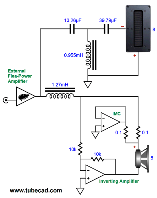
(I made this image back in 2017, which explains the 400Hz crossover frequency.) The tube-based power amplifier is happy, and we got away with a smaller inductor and 8-ohm woofers. How does the SPL work out for the two woofers? Each woofer sees 70.7% as much signal as the fullrange, so each woofer will deliver 3dB less SPL, but since we gain 6dB due to the doubled surface area, the net SPL will be 3dB higher than their rated SPL. For example, 91dB woofers will deliver 94dB. What if we are using a solid-state power amplifier and two 8-ohm woofers? Assuming the two drivers are in parallel, making a 4-ohm load, their combined output will be 6dB higher. For example, 88dB woofers combined will deliver 94dB of SPL. Of course, the solid-state amplifier will have to work into a 4-ohm load at low frequencies, which might make it run too hot. If we placed the two 8-ohm drivers in series, each driver will suffer a -6dB reduction in SPL, but gain 6dB due to twice the radiating surface, so no change in SPL. In addition, the power rating will effectively double with the woofers in series, so two 50W woofers can handle 100W of amplifier output. As I pondered all this, some of my power-boosting circuits for use with flea-powered amplifiers came to mind. Post 261 and Post 552 show many examples of using an internal power amplifier in a loudspeaker to augment the small external power amplifier's output. Here is an example from post 552:
The flea-power amplifier drives the tweeter through the 3rd-order passive filter. It also half drives the woofer through the impedance-multiplier circuit (IMC), which along with the bottom amplifier effectively makes the flea-power amplifier's power output four times larger.
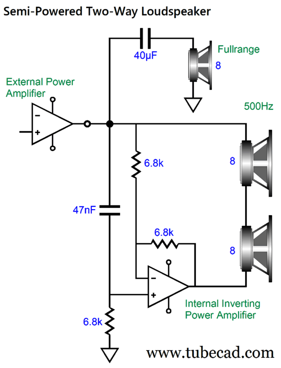
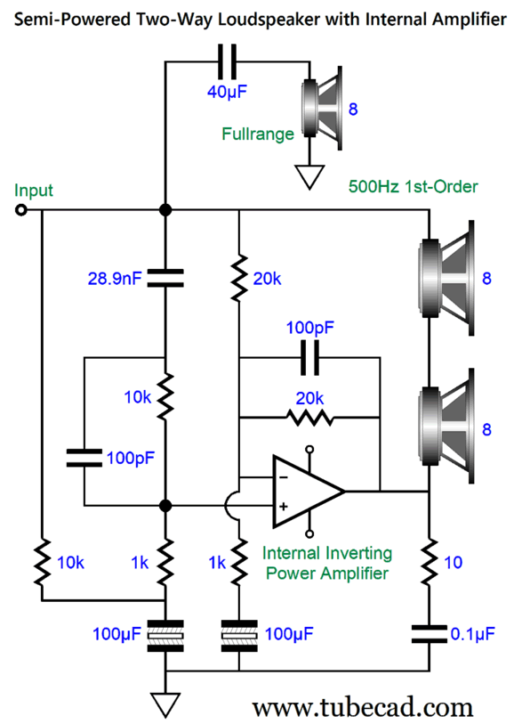
This is an asymmetrical crossover, as the tweeter sees a 3rd-order high-pass filter, while the woofer sees a 1st-order low-pass filter. Note that no inductor was used in the woofer's circuit. (Inductors are a pain, as they are both large and expensive. Moreover, they can act as hum magnets and always present some DCR. In addition, if they are not air-core, they can saturate, adding much distortion.) Without the IMC, the 8-ohm woofer would present a 4-ohm-load impedance to the flea-power amplifier. On the other hand, if we used a 16-ohm woofer and no IMC, the external power amplifier would work into an 8-ohm load. Okay, let's look at a 1st-order two-way crossover with a matching internal power amplifier.
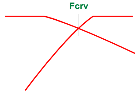
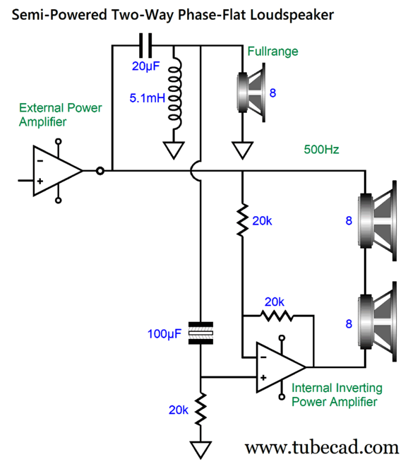
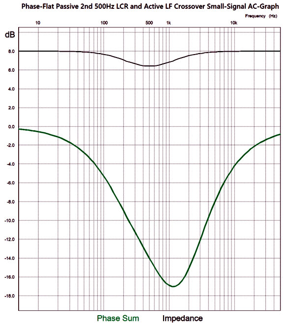
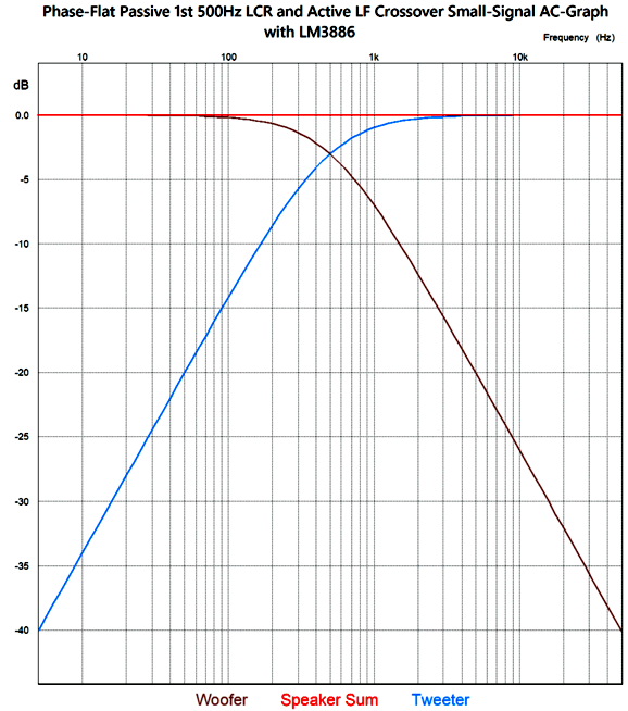
At low frequencies, in contrast, the internal power amplifier inverts the external amplifier's output signal. Since a loudspeaker driver is an intrinsically differential device, the woofer only responds to low frequencies, as that is only time when it sees as a differential signal across its terminals. The 47nF capacitor and 6.8k resistor in series set the 500Hz crossover frequency. The formula is easy enough: C = 159155/F/R Where C is in µF and F is the crossover frequency. As far as the external power amplifier is concerned, it is connected to an 8-ohm woofer that is in series with a loss-less inductor. Yes, the internal power amplifier mimics an inductor. Think about it: the higher the frequency above the crossover frequency, the less current the external amplifier delivers into the woofers, just as an inductor would bring about. This setup yields both a flat phase and impedance output, along with the required flat frequency response. Well, as flat as the drivers allow. One way of thinking about this arrangement is that the internal power amplifier matches the power delivered by the external power amplifier into the woofer, making this a semi-powered loudspeaker design. What will be the resulting two-woofer SPL? Since we doubled the woofer radiating surface, we gain 6dB in SPL, so two 88dB woofers will produce 94dB of SPL at one meter with 2.828Vrms signal from the external power amplifier.As it is altogether impossible for me to leave any circuit alone, I wondered if I couldn't force a steeper (higher-order) filter slope on the fullrange driverand still retain a phase-flat output. It turns out that I could.
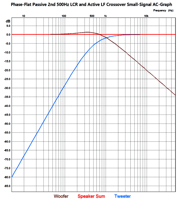
The graph begins at 5Hz and ends at 50kHz. What do the impedance and phase plotlines look like? Not as flat as I would like, but still fantastic.
By the way, I tried this topology with a 3rd-order high-pass filter on the fullrange. It still worked, but the loudspeaker impedance fell to 4 ohms at the crossover frequency. Why bother with steeper slopes for the fullrange? Increased power handling. In order for a fullrange to exhibit good high-frequency response, its diaphragm must be light and its voicecoil cannot present too much inductance—all of which tends to limit its power handling ability. Producing deep bass requires power.
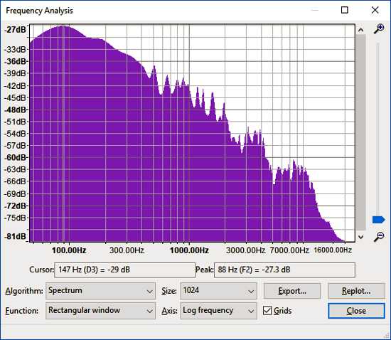
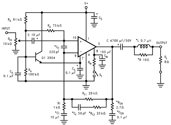
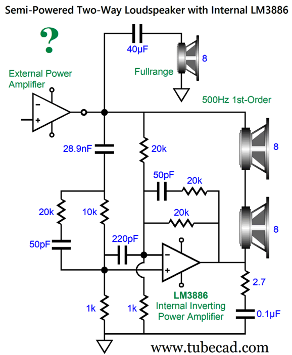
If you examine spectrographs of music recordings, you see that the bulk of power demand occurs in frequencies below 600Hz. Of course, some rare counterexamples can be found—say some synthesizer-based electronic music. Moreover, two-way loudspeakers with a horn high-frequency driver demand at least a 2nd-order high-pass filter for safety. The big problem is finding unity-gain stable power amplifier to enclose within the loudspeaker cabinet. The OPA541 would work, but most IC power amplifiers, such as the LM3886 and TDA7293, are nowhere near unity-gain stable. The following 1st-order crossover workaround might work out well, even with an LM3886 that is NOT unity-gain stable. Here is a schematic from the LM3886 datasheet.
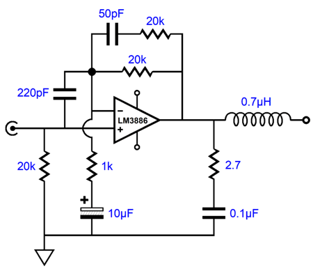
Next, I have to develop some way to retain all the essential compensations parts( 50pF, 220pF, 0.1µF capacitors, 2.7 and extra 20k negative feedback loop resistor) while still maintaining a 1st-order low-pass filter and a combined phase response. Here is my solution:
The idea here is that we are throwing away negative feedback, as the LM3886 seemingly functions as a unity-gain inverting amplifier, but internally it is amplifying by 1:11 (+20.8dB), which explains why its non-inverting input signal is attenuated by 1/11. I do not have a SPICE model for the LM3886, which explains the question mark, so I used the ideal-OpAmp model to run the SPICE simulations on the circuit shown above. Here are the resulting square-wave plotlines.
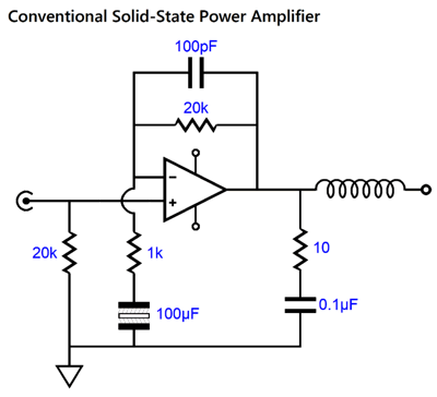
Perfect. Unless you are an artist, writer, gambler, or someone who has just fallen in love, you cannot imagine the thrill I feel when one of my intuitive flashes pans out, i.e. when an instant and spontaneous circuit topology glints in my mind and then, after being captured, passes the test in SPICE simulations. Well, this arrangement of parts just plopped into my mind, aided—no doubt—by the requirement for symmetry. Symmetry, what symmetry? The 10k resistor equals the two 20k negative feedback loop resistors in parallel; the added 50pF capacitor and 20k resistor balance the pair in the negative-feedback loop. Okay, but what about a more conventional solid-state power amplifier design? For example, the following is a common arrangement.
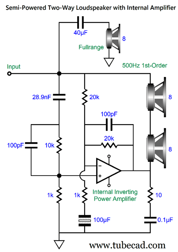
What is missing is a complementary capacitor to the 100µF non-polarized electrolytic capacitor terminating the 1k feedback resistor. (The 100µF capacitor further reduces any inherent DC offset, as it increases the available negative feedback at DC. Effectively it turns an amplifier into a unity-gain buffer at DC and ultra-low frequencies.) Transistor-based input stages draw some current from their inputs, albeit a tiny amount. Ideally, each input should see the same resistance to decrease any DC offset at the output. For example, a 20k negative feedback loop resistor should be balanced with a 20k input resistor to ground. In the schematic above, symmetry is broken, as we see a 1k resistance to ground, not 20k. (Actually the two 20k resistors are effectively in parallel, so 10k resistance is needed.) In addition, the external power amplifier might impose its own DC offset, which the internal power amplifier must mimic, in phase. In other words, if both power amplifiers deliver the same DC offset, the two woofers will be blind to it. (The fullrange driver is blind to the DC due to its coupling capacitor.) Here is my solution:
The added 100µF non-polarized electrolytic capacitor and 10k resistor relay the entire external power amplifier DC offset to the internal power amplifier's non-inverting input. The 10k resistor equals the two 20k negative feedback loop resistors in parallel. Sweet symmetry. (Actually, a 9.1k resistor would prove the better value, as it would be in series with the 1k resistor, making a total resistance of 10.1k.) Where is the output inductor? I do not think that we need it, as the two woofers already present their own intrinsic and considerable series inductance (Le) and the wiring within the loudspeaker enclosure is short. (Long, fancy loudspeaker cables and complex passive crossovers laden power amplifiers with excessive capacitance.) Note the internal power amplifier should match in output power the external power amplifier. With external tube-based single-ended power amplifiers, this no big deal, as little power is needed. With 200W external power amplifiers, however, we have to forget about class-AB chip amplifiers and think class-D amplifiers. The problem with class-D amplifiers is that many of the high-power amplifiers are actually bridge amplifiers, which cannot be used in my setup. A good question to ask is this trip really necessary? Why not just use two 4-ohm woofers and an inductor? Two answers come to mind: inductors are a pain; fullrange driver tend to deliver high SPLs, which are hard to match with typical woofers. My arrangement eliminates the big inductor and adds 6dB of SPL to the woofer output. |
I know that some readers wish to avoid Patreon, so here is a PayPal button instead. Thanks.
John Broskie
John Gives
Special Thanks to the Special 82 To all my patrons, all 82 of them, thank you all again. I want to especially thank
All of your support makes a big difference. I would love to arrive at the point where creating my posts was my top priority of the day, not something that I have to steal time from other obligations to do. The more support I get, the higher up these posts move up in deserving attention.
If you have been reading my posts, you know that my lifetime goal is reaching post number one thousand. I have 415 more to go. My second goal was to gather 1,000 patrons. Well, that no longer seems possible to me, so I will shoot for a mighty 100 instead. Thus, I have just 18 patrons to go. Help me get there. Thanks.
Only $9.95
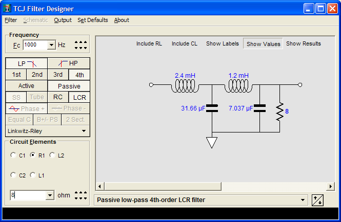
The Tube CAD Journal's first companion program, TCJ Filter Design lets you design a filter or crossover (passive, OpAmp or tube) without having to check out thick textbooks from the library and without having to breakout the scientific calculator. This program's goal is to provide a quick and easy display not only of the frequency response, but also of the resistor and capacitor values for a passive and active filters and crossovers. TCJ Filter Design is easy to use, but not lightweight, holding over 60 different filter topologies and up to four filter alignments: While the program's main concern is active filters, solid-state and tube, it also does passive filters. In fact, it can be used to calculate passive crossovers for use with speakers by entering 8 ohms as the terminating resistance. Click on the image below to see the full screen capture.
Tube crossovers are a major part of this program; both buffered and un-buffered tube based filters along with mono-polar and bipolar power supply topologies are covered. Available on a CD-ROM and a downloadable version (4 Megabytes). Download or CD ROM
|
|||

More Balanced Circuits As I have said before many times, audio lives off the crumbs that fall off the technology table. With the exceptions of the 300B, 6EU7, ring-emitter transistors, few mainstream electronic parts were designed with audio applications in mind. Boutique electronic parts do not count, unless you do not mind paying $30,000 for an 8-watt power amplifier. A forty-dollar resistor may sound better than a four-cent resistor, but it will never be part of a normal audio device. Technological development can change directions, instantly. For example, I expect the quest for the perfect battery will be put on hold, when a truly super-capacitor is invented. Remember, capacitors actually store electrical charge, while batteries store the potential to generate current flow through electro-chemical reactions. Such a super-capacitor will revolutionize not only electric cars but also audio. Imagine turning on a power amplifier and, once all the super-capacitors are charged up, the amplifier disconnects from the wall voltage; no rectifier ripple, no RFI and light dimmer induced electrical noise; just pure DC. (Or, maybe not. These super-capacitors will be, no doubt, high-voltage capacitors, as doubling the capacitor voltage quadruples the Joules. Voltage² means high-voltage is the answer. In other words, not 3.3Vdc but something closer to 330Vdc—perhaps, 3.3kVdc.) In short, we music-loving solder-slingers must always be on the outlook for something new and technical to exploit, develop, utilize. A few weeks ago, I stared at the two XLR output jacks on the back of my DAC, and my mind filled with ideas on how to exploit the balanced signals. Soon, my sketchpad filled with schematics. One idea that immediately came to mind was using the balanced outputs to drive a headphone amplifier, while my unbalanced line-stage amplifier and power amplifiers got the unbalanced signals. 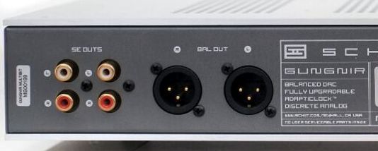
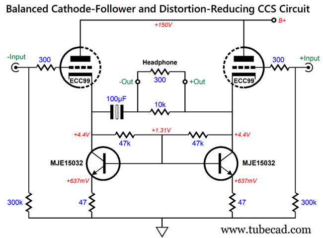
My DAC, a Schiit Gungnir rev-B multibit, puts out a balanced signal of 4Vrms (if I remember correctly) which equals 5.6V peak-to-peak. In other words, that is more than enough voltage swing to drive my Sennheiser HD650s in balanced configuration to more SPL than I can withstand. A decade ago, I performed an experiment: I played music at a highest volume level I could tolerate, and then I hooked up my oscilloscope to measure the peaks. About 3Vpk was the highest voltage peak I recorded. In other words, the XLR balanced output is hot enough, but lacks the needed current delivery. Here follows a simple balanced cathode follower circuit with fancy distortion-reducing constant-current sources.
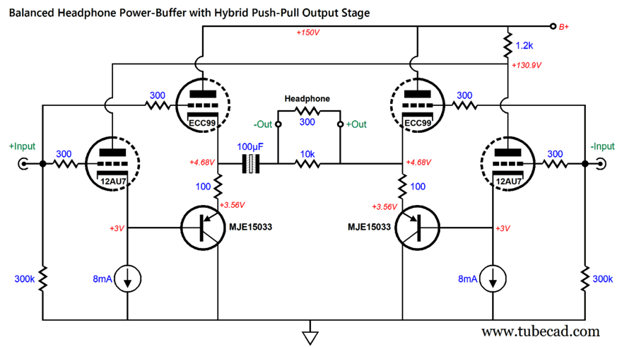
Note that a 4.4V DC offset exists on both outputs, the result of using only one output coupling capacitor. Is this a problem? I don't think so, as the headphone driver cannot see any net differential DC voltage. In addition, 4.4Vdc is not a lot of voltage, so I have no fear of high-voltage shocks. Since both cathodes are at the same DC voltage, why not forgo the output coupling capacitor altogether? In SPICE simulations, we can do so, since in SPICE the two triodes and the two transistors and all the resistors are perfectly matched; reality is not likely to prove so helpful. In other words, we can expect a DC offset between cathodes in reality. (See my last post for more information on the distortion-reducing constant-current sources.) Of course, the cathode followers do not actually deliver 100% unity-gain, so we should not expect to see the full 5.6V of peak-to-peak voltage swing. Even 4V peak-to-peak is, however, plenty loud. What if your DAC only puts out, peak-to-peak, 2Vrms? The following balanced headphone amplifier offers 6dB of gain. 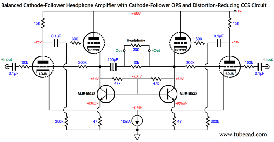
This is a balanced amplifier, not a unity-gain buffer. The input 6DJ8 triodes provide balanced gain and control the ECC99 outputs, as the 100k and 200k resistors form the negative feedback loops. In other words, this balanced amplifier uses negative feedback to lower distortion and output impedance. The input coupling capacitors are needed as the negative feedback loop terminates directly to the cathode. In addition, the 4.4Vdc 6DJ8 grid voltage allows us to use a constant-current source in place of a shared cathode resistor. The constant-current source furthers the circuit's CMRR and balance.
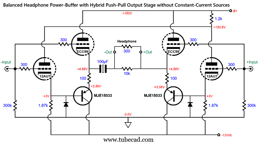
Balanced Headphone Buffer with Hybrid Push-Pull OPS
The -12Vdc rail allows us to use a far large cathode resistor value, and it can also power the tube heater elements. The two diodes are safety devices that only conduct at start-up, when the cold cathodes have yet to emit electrons. In addition, this arrangement allows for much larger output voltage swings.

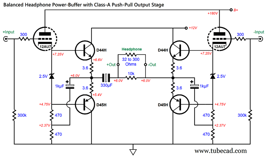
Balanced Headphone Power-Buffer with Solid-state Push-Pull OPS
The D44H and D45H are TO-220 power transistors, with 60V voltage rating and 70W power limit. The idle current each transistor experiences is 167mA idle current flow, which is rich for a headphone buffer, as it implies a peak output current swing of over 0.3A within the class-A window of operation. The problem with this design is that the two 2.5V zener (or LM431 or TL431) does not provide temperature-compensation for the output transistors. In other words, the hotter the output transistors get, the more current they draw. One workaround is to use an auto-bias configuration. 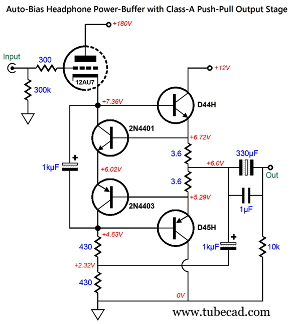 Only half of the balanced buffer is shown, so as to avoid mental clutter. By the way, this would make a fine power buffer for unbalanced headphone driving. The 2N4401 and 2N4403 transistors monitor the voltage drop across the two 3.6-ohm emitter resistors. As the output transistors get extra hot, their base voltages drop correspondingly. Yes, there is a slight climb in idle current flow with an increase in temperature, but is too tiny to trouble us, amounting to only a few milliamperes per 100C degrees increase in temperature. To make a balanced version simply requires doubling the circuit. What is the output impedance in the balanced configuration? About 3.6 ohms, the value of a single emitter resistor. In SPICE simulations, the distortion was low: 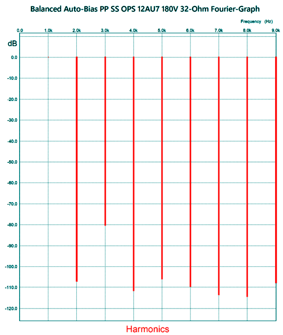
The simulation was with 1Vpk of output at 1kHz into a 32-ohm load. I wish the 3rd harmonic was suppressed more deeply, as it contributes a deadening sound. Still, to be -80dB down means that the distortion signal is only 0.01% (or 1/10,000th as large as the fundamental). I wondered what the harmonic structure looked like with a single output driving an unbalanced 32-ohm load to 1Vpk. 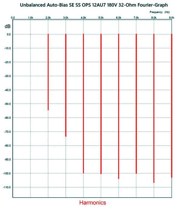
The THD is certainly higher, but the harmonics cascade takes on a lovely single-ended structure. Speaking of single-ended, let's move on to some balanced single-ended variations.

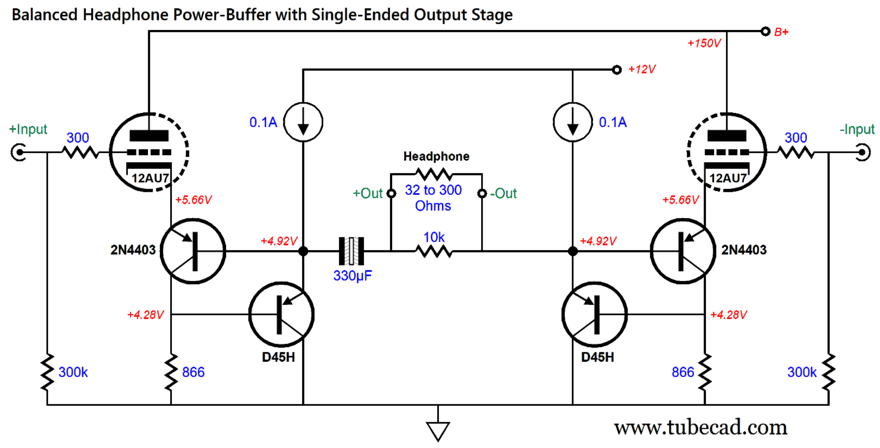
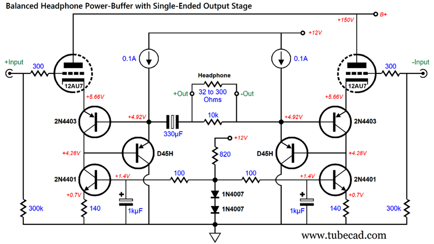
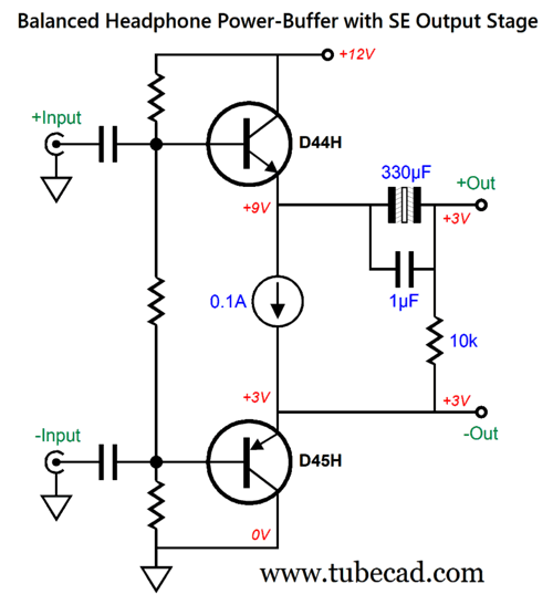
Balanced Headphone Power-Buffer with Single-Ended Output Stage The 100mA constant-current sources instantly auto-bias the two output stages. LM317 voltage regulators make fine 100mA constant-current source with the addition of a 12.4-ohm current-sense resistor. It may not look as if any negative feedback is used, but it is. The PNP transistor 2N4403 transistors relay the output signal to the 12AU7 cathodes, which the 12AU7 triodes then compare to the input signal present on their grids. Any deviation is straightened out by the triodes. Well, that is within the limitations imposed by the weak triode transconductance. Effectively, the 12AU7 are configured as inverted cascodes, but the 12AU7's weak transconductance against the 866-ohm collector resistor develops little gain; and, thus, little negative feedback. The workaround is to replace the resistors with constant-current sources. The 2N4401 NPN transistors function as constant-current sources, which use the shared diode string as their voltage reference. By the way, we can do the same for the constant-current sources that load the D45H PNP transistors. 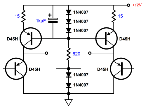
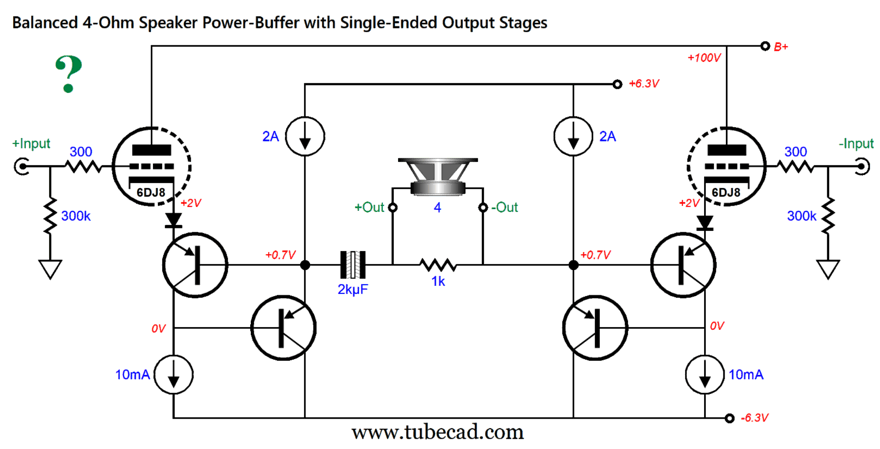
Both top and bottom sets of constant-current sources share the same diode string. If we use a low-voltage bipolar power supply, we could even drive 4-ohm loudspeakers. The question mark denotes that I haven't run any SPICE simulations on this variation. It is quite possible that two extra PNP transistors are needed to create Darlington output devices, as more current-gain might be required. With 8Vpk of output swing, the 4-ohm speaker would dissipate 16W, which is an impressive amount for a single-ended class-A power buffer. Bear in mind that, in spite of the wee bipolar power supply voltages, the output devices and constant-current source will run hot—50.4W per channel. Class-A isn't for the faint-hearted.
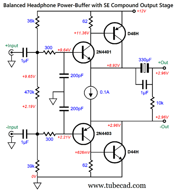
 Vertical Single-Ended OPS
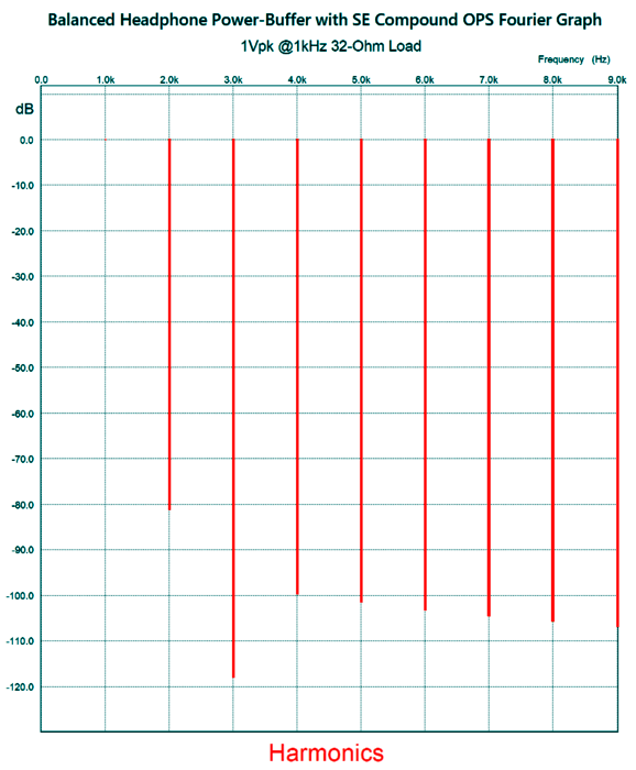
The compound configuration greatly reduces the distortion and output impedance, while decreasing the input current-drive requirement, but at the cost of truncating the maximum output voltage swing to about 3.5Vpk. (Of course, we could a 15Vdc power supply instead.) I just about spat out my coffee, when I beheld this circuit's SPICE-generated Fourier graph.
Both will work, but we could get extra fancy.
Music Recommendation: Yussef Kamaal, Black Focus Both Amazon Music and Qobuz offer the album in 24-Bit, 44.1kHz format. Today, while driving about town, my local classical radio station informed me that today was Mick Jagger's 80th birthday. In his honor, they played the classic Stones song, Paint It Black, performed by Eric Henderson on classical guitar. I quite enjoyed it, finding it surprisingly melancholy and somber.
//JRB
Did you enjoy my post? Do you want to see me make it to post 1,000? If so, think about supporting me at Patreon.
User Guides for GlassWare Software
For those of you who still have old computers running Windows XP (32-bit) or any other Windows 32-bit OS, I have setup the download availability of my old old standards: Tube CAD, SE Amp CAD, and Audio Gadgets. The downloads are at the GlassWare-Yahoo store and the price is only $9.95 for each program. http://glass-ware.stores.yahoo.net/adsoffromgla.html So many have asked that I had to do it. WARNING: THESE THREE PROGRAMS WILL NOT RUN UNDER VISTA 64-Bit or WINDOWS 7, 8, and 10 if the OS is not 32-bit or if it is a 64-bit OS. I do plan on remaking all of these programs into 64-bit versions, but it will be a huge ordeal, as programming requires vast chunks of noise-free time, something very rare with children running about. Ideally, I would love to come out with versions that run on iPads and Android-OS tablets. |
||||


| www.tubecad.com Copyright © 1999-2023 GlassWare All Rights Reserved |