| John Broskie's Guide to Tube Circuit Analysis & Design |
15 August 2023 Post Number 586
Bi-Amp +40dB Phono Stage with 500Hz Crossover
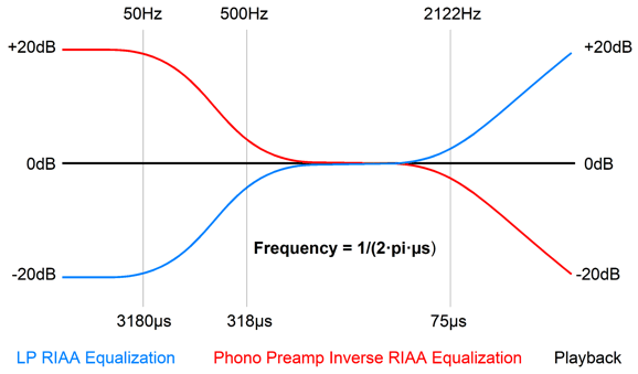
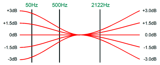
Yes, my phono/crossover created bi-amped outputs. In other words, I didn't just tack on two output filters; instead, I used the LP's inherent RIAA equalization as the foundation for a 500Hz crossover frequency. Essentially, I built an internally bi-amped phono stage. (Actually, my first attempt was a tacked-on set of filters; later, I decided to exploit the RIAA EQ on the LP.) If we inspect the RIAA equalization imposed on the LP, we can see how this is possible.
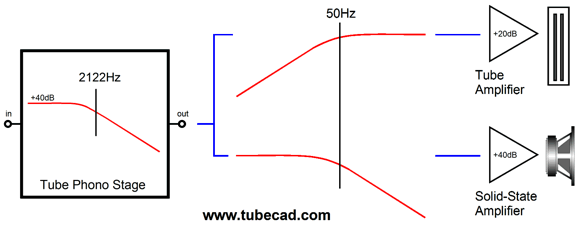
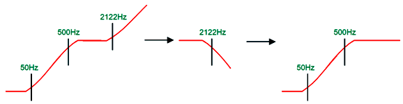
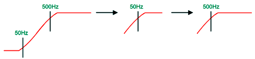
Up to 50Hz and from 500Hz to 2122Hz, the LP's engraved signal is flat. From 50Hz to 500Hz and from 2122Hz up, the signal rises at a 1st-order slope of 6dB per octave, 20dB per decade. If we impose a 2122Hz low-pass filter upon the LP's signal, we get the following frequency plot.
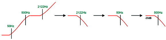
Now that we have one-half of our two-way active filters, we must derive the complementary 500Hz low-pass filter. We start with the same 2122Hz low-pass filter upon the LP's signal and then pass the resulting signal through a 50Hz low-pass filter.
The only problem is that the low-pass filter signal is -20dB lower than the 500Hz high-pass filter signal, which means that we must add 20dB of amplification to the low-pass filter output.
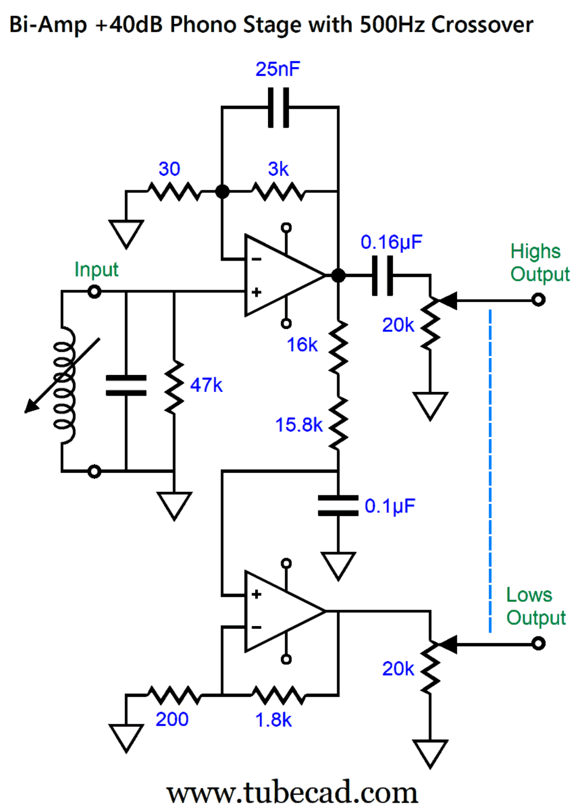
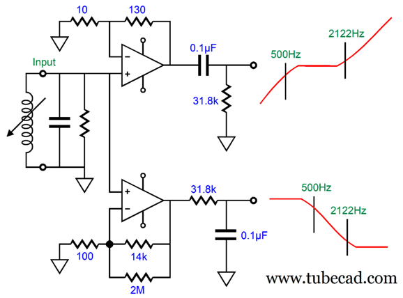
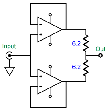
Sounds complicated, but all we need is two OpAmps per channel and a few resistors and capacitors.
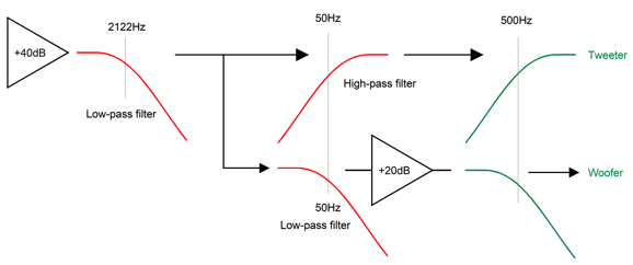
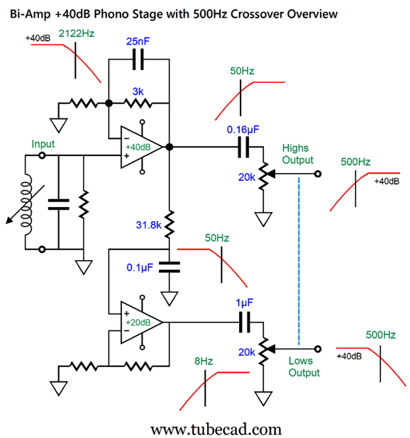
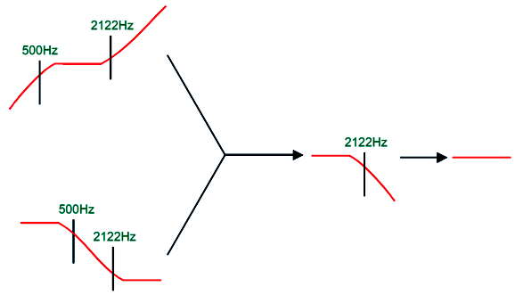
This is a 40dB phono preamplifier with bi-amp outputs at a 500Hz crossover frequency. The top OpAmp provides a gain of 40dB (1:100) and imposes a 2122Hz low-pass filter due to the 25nF capacitor shunting the 3k negative feedback resistor. The 0.16µF output coupling capacitor and 20k volume control potentiometer impose a 50Hz high-pass filter upon the output signal that the high-frequency power amplifier sees, thereby completing the 1st-order 500Hz high-pass filter. The 16k and 15.8k resistors in series combine to a resistance of 31.8k, which when terminated into the 0.1µF capacitor results in a 50Hz low-pass filter. The bottom OpAmp provides a gain of 20dB (1:10), bringing the gain back up to 40dB. Stunningly simple, no? Here is the big-picture overview:
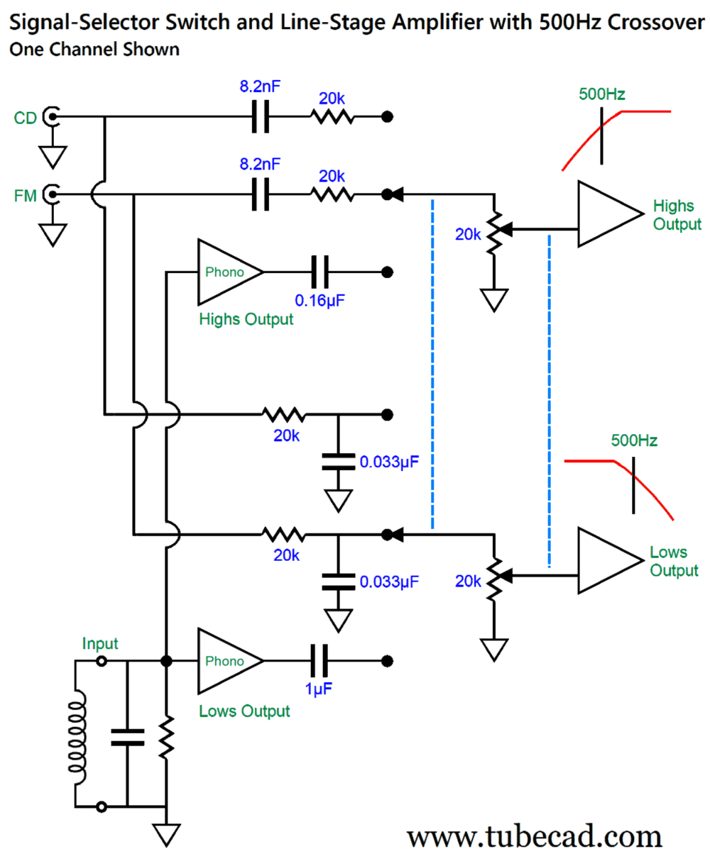
By the way, the dashed blue line implies that the potentiometers are ganged together; i.e. they share the same shaft, so all the potentiometer wipers move in unison. For stereo use, a four-ganged volume potentiometer will be needed. Observant and knowing electronic practitioners will note that the high-frequency output signal will begin to rise above 212.2kHz, as the top OpAmp's low-pass filtering flattens at that frequency, as that is the frequency at which the OpAmp ceases to amplify and becomes merely a unity-gain buffer. True. But how much actual output at 212.2kHz do you expect from the record cutting lathe and from your stamped LP and phono cartridge and power amplifier and high-frequency driver? Simply adding ferrite beads to the input might be enough to banish the rise above 212.2kHz. Or, you could shunt the 18k negative feedback resistor with a 43pF capacitor to ensure that the low-frequency output doesn't rise above 212.2kHz. When I built my bi-amped phono stage, CDs didn't exist (the CD released in 1982, but I bought my first CD player in 1984), but FM and tape did. How can we select a signal source other than phono? In other words, how do we select a signal source that does not already offer bi-amped outputs? What is needed is an input-signal selector switch like my GlassWare Select-2 switch that holds a 3-position, four-pole rotary switch.
The CD and FM signals pass through passive 500Hz filters and undergo -6dB attenuation. The attenuation is a necessary part of the filtering due to the 20k potentiometer load. The following line-stage amplifier need only provide a gain of 12dB to 20db. What if more than 40dB of gain is needed, say if an MC cartridge is used? All we need to do is lower the 30-ohm resistor's value. Replacing the 30-ohm resistor with a 10-ohm resistor buys us an increase of 9.6dB of gain; a 3-ohm resistor, +20dB of gain, bringing the total gain to 60dB. Okay, no doubt some readers are thinking: that's great, John, but where the hell are the tubes?
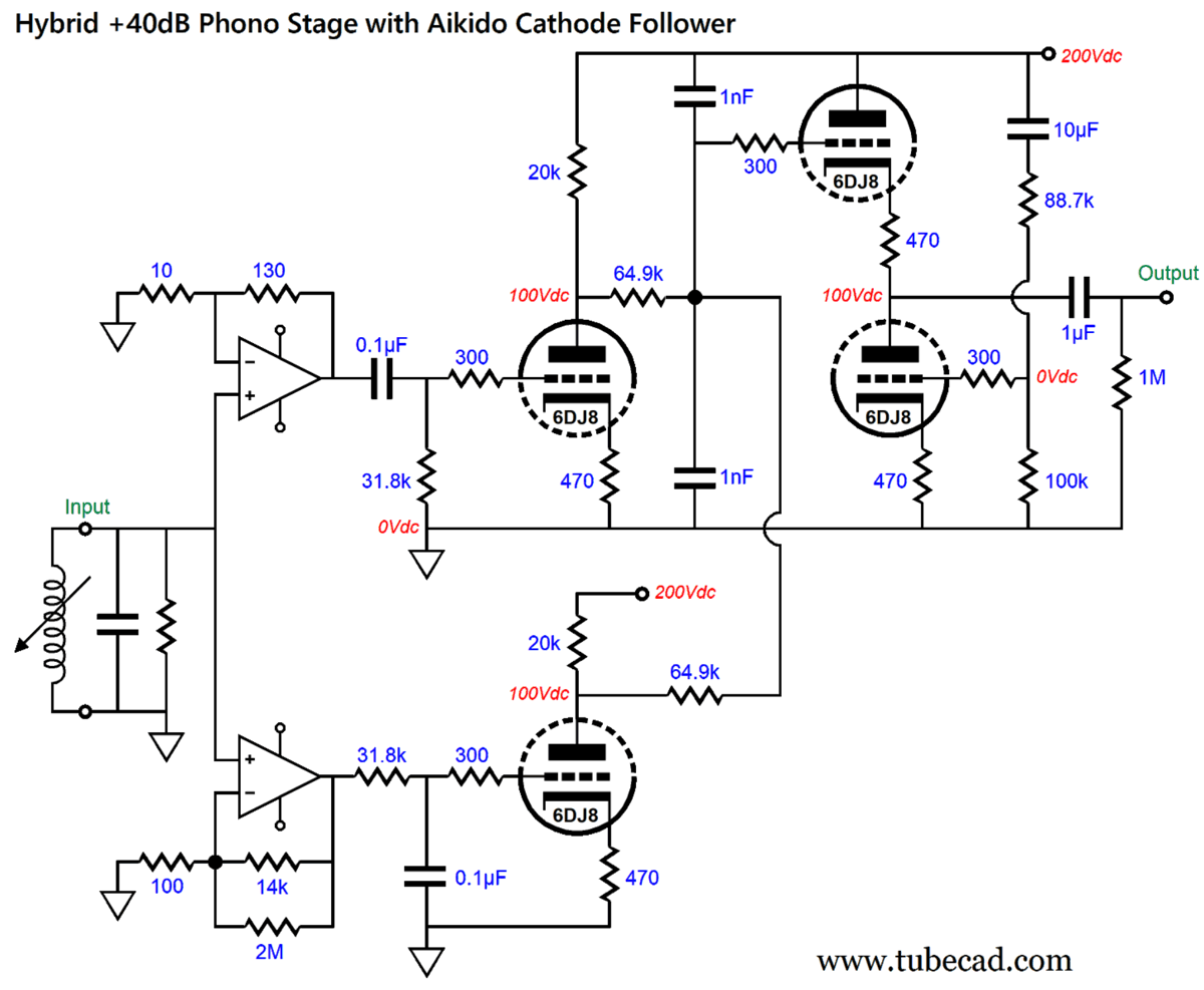
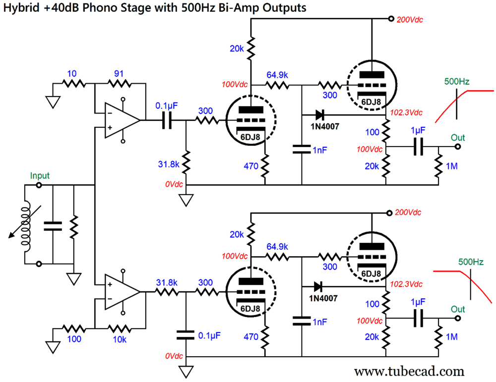
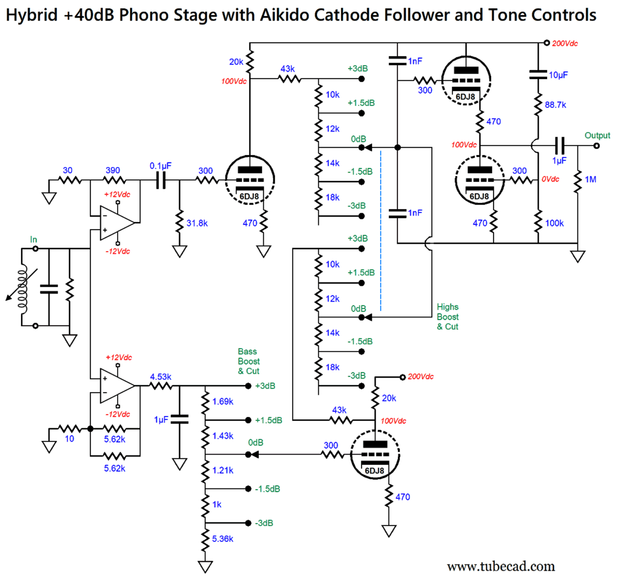
Hybrid +40dB Phono Stage with Aikido Cathode Follower
The RIAA's 318µs time constant (500Hz) figures big in this design, as the phono stage contains an internal 500Hz crossover. That's right, it's internally bi-amped. The top OpAmp delivers a gain of 1:14 (+22.9dB), while the bottom OpAmp produces a gain of +42.9dB. The top OpAmp's output signal travels through a 50Hz high-pass filter, which combined with the LP's RIAA equalization creates a 500Hz high-pass filter. The bottom OpAmp's output signal travels through a 50Hz low-pass filter, which combined with the LP's RIAA equalization creates a 500Hz low-pass filter.
All that remains is to impose a 2122Hz (75µs) low-pass filter, which the two 64.9k resistors and two 1nF capacitors achieve after the 6DJ8 triodes deliver a gain 1:15 (+23.5dB). We lose 3dB of signal through the two 64.9k resistors, which function also as a signal mixer, resulting in a final gain of 40dB.
The Aikido-cathode-follower output stage strips away the power-supply noise from the output signal and provides a low-impedance output. If a conventional cathode follower were used, then the two 1nF capacitors could be replaced with a single 2nF that terminates into ground, but we would lose the PSRR enhancement provided by the ACF output stage. Of course, with a well-regulated B+ voltage, this is less of a concern. Here is a bi-amp version with simple cathode followers.
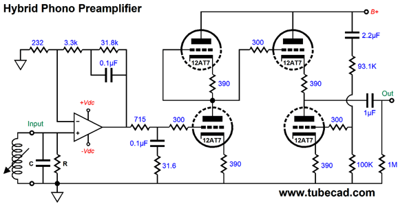
Note the reduction of gain from the OpAmps. Why? Since the 64.9k resistors no long act as a mixer circuit, there is no longer a -3dB insertion loss. No doubt, some will query the need for so complicated a hybrid phono stage, as a single OpAmp driving a tube-based gain stage would suffice. Here is just one possible alternative circuit from post 555.
The 50Hz and 500Hz portion of the inverse RIAA equalization is actively handled by the OpAmp negative feedback loop, while the remaining 2122Hz portion is passively accomplished by the low-pass filter following the OpAmp. The Aikido gain stage sees a flat input signal. So, how do I defend the added complexity of the internally bi-amped hybrid phono stage? Answer: tone controls.
By skewing the inverse RIAA transition frequencies, we can prompt either a bass boost or cut, and either a highs boost or cut, or some combination of both.
A 5-position, two-pole rotary switch is needed for the bass tone control in a stereo phono preamp, while a 5-position, four-pole rotary switch is needed for the highs tone control. One way of thinking about this setup is that we are getting tone controls for free, as we are simply exploiting the characteristics of the RIAA equalization recorded on the LP. In other words, other than the need for rotary switches and a handful of resistors, no additional frequency-selective capacitors are needed.
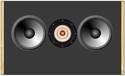
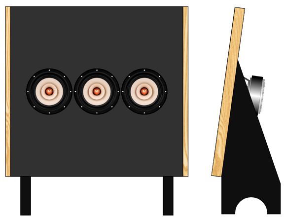
Quad-Like Two-Way Loudspeaker
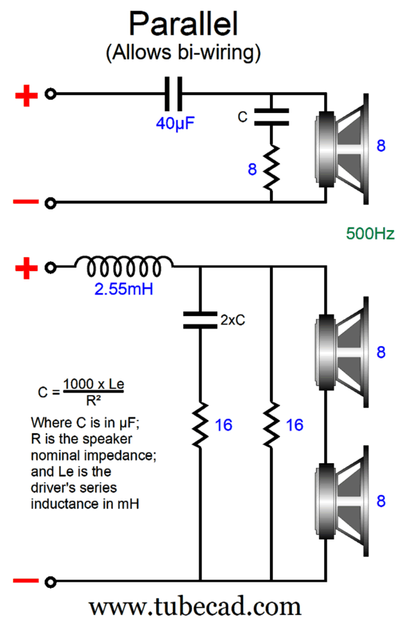
The huge advantages are matched frequency and phase responses, along with equal SPLs, the result of using the same drivers throughout. That last feature, equal SPL, will take some manipulation, however, to avoid a 6dB boost in the bass frequencies due to the doubled woofer radiating area. In addition, two 8-ohm drivers in parallel equal a 4-ohm load; in series, a 16-ohm load. If we place the two low-frequency drivers in series and shunt the pair with a 16-ohm power resistor, we get an 8-ohm load. What about the resulting SPL? Since each driver sees half the signal voltage, we lose 6dB in SPL from each driver; but as we have doubled the radiating area, we gain 6dB, returning us to a combined SPL equal to a single driver. Here is a simple 1st-order parallel passive crossover.
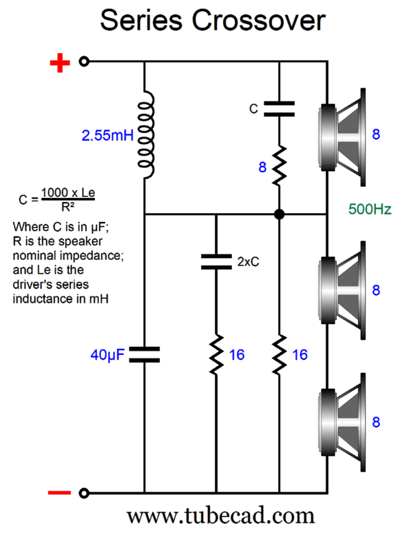
This arrangement allows us to bi-wire the loudspeaker. The Zobel network is interesting, as we must double the capacitor value in the low-frequency filter, as the fullrange driver's own internal series inductance is double, as its impedance. The series arrangement uses the same capacitor and inductor values, but differently arranged.
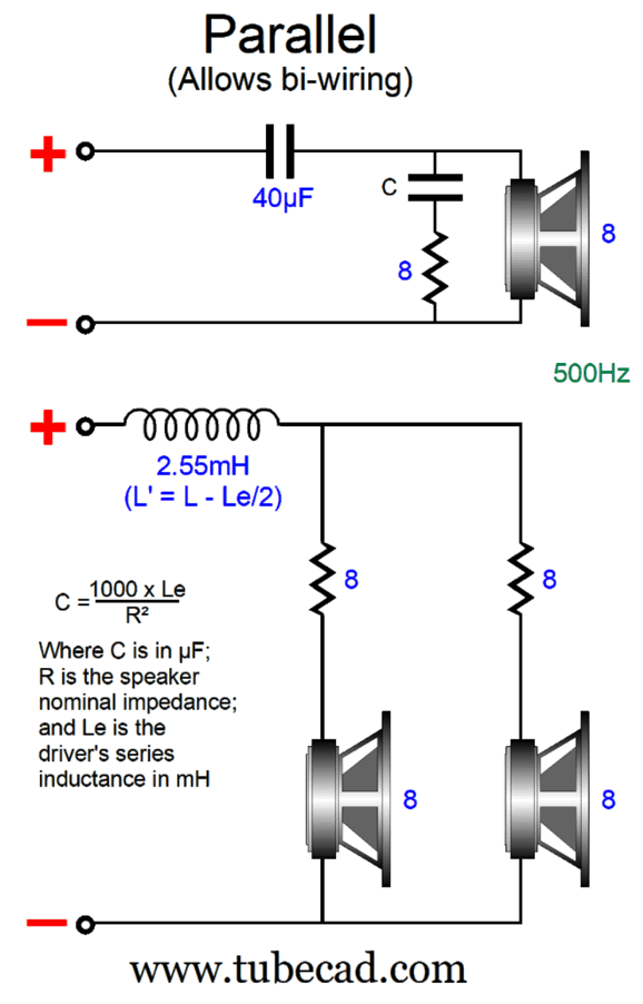
One possible problem with placing the low-frequency drivers in series is that the parallel 16-ohm resistor will decrease the drivers' Qes, which in turn will decrease their Qts, making for thinner bass due to the over-damping. In contrast, placing a resistor in series with a woofer will increase the driver's Qes, thereby increasing the Qts. Since most woofers are used in either an acoustic-suspension (seal box) or bass-reflex (ported) enclosures, the Qts is made purposely low, as the enclosures will raise the Q substantially. Sadly, this makes most woofers unsuitable for dipole loudspeakers, as the extra-low Qts results in very thin bass. Most dipole loudspeakers use weakly damped woofers (or planar diaphragms) with Qs above 1 to undo the bass loss due to the narrow panel width. One workaround is to add series resistance to the woofers. We can use the formulas from post 396: Qes (new) = Qes*(R+RDC) / RDC Where Qes is the electrical part of woofers Q-Factor, and R is the added resistance in series with the woofer. To arrive at the new Qts (total Q) we must place the existing Qms (mechanical Q) in parallel with the new Qes. See post 396 for more details on series resistors and woofers.
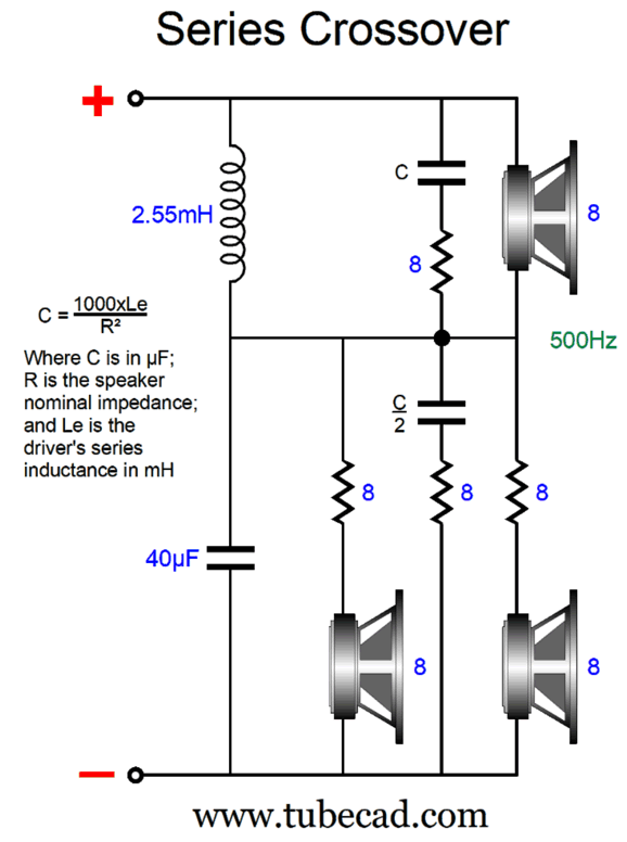
The assumption here is that the same fullrange driver is used throughout. Each low-frequency driver gets its own 8-ohm series resistor, which will halve the signal voltage, resulting in a -6dB loss of SPL. But as we have doubled the low-frequency radiating area with the two low-frequency drivers, we gain 6dB, returning us to the original SPL. No Zobel network is required for the low-frequency drivers, as their own Le series inductance becomes part of the low-pass filter design. The high-frequency driver, however, needs a Zobel network. Creating a series- version of the crossover requires one small twist.
A Zobel networks are used throughout, but the low-frequency drivers need a Zobel capacitor of half the value of the high-frequency driver's Zobel capacitor. Why? The two low-frequency drivers are in parallel, so their inductances are also in parallel, which halves the inductance. This is the passive crossover I would build, as the series topology works better with voltage-out power amplifiers, which the overwhelming majority of power amplifiers are. In addition, shunting a loudspeaker driver with a reactive component (i.e. a capacitor or inductor) damps the driver in the range of frequencies beyond its intended range.
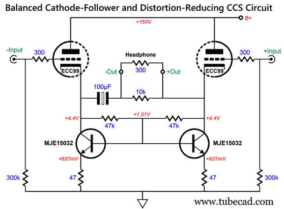
Balanced Cathode-Follower and
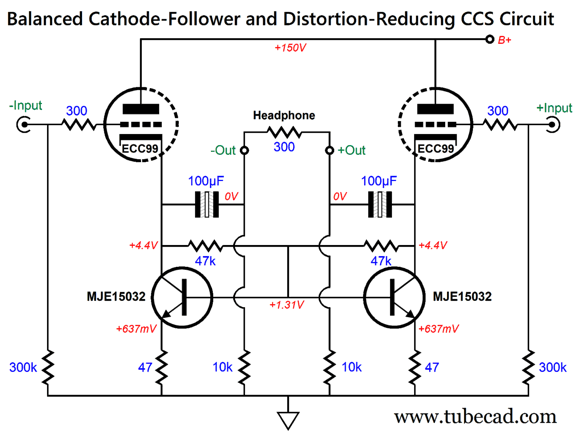
Note the 4.4Vdc DC offset present on both output terminals and the single output coupling capacitor. We could add an additional output coupling capacitor and two resistors to eliminate the DC offset, which although safe might prove bothersome to many.
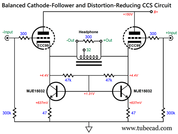
Another workaround would be to use an output transformer.
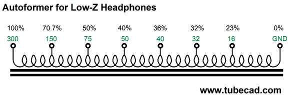
The transformer blocks the DC on the primary from appearing on the secondary. In addition, output transformer can hold a low-impedance output tap. The assumption here is that the 300-ohm headphones would reflect as a 300-ohm load to the cathode followers, so the transformer would be a 1:1 isolation transformer. For the 32-ohm output, we would tap at one third of the secondary winding. For example, if three layers of wire were laid down, then we would tap at the end of the first layer. An output transformer's impedance ratio is equal to winding ratio squared. With the 32-ohm tap, we have effectively a 3:1 ratio, which squared equals 9:1, so the 32-ohm load reflects to the primary as a 288-ohm load. Another workaround would be to use an autoformer.
The DC offset is back, but the autoformer protects the headphone driver just as much as a coupling capacitor would, as the winding's low DCR shunts the driver, so even if one of the triodes were defective or missing, the driver voicecoil would see very little DC voltage differential. (An ideal winding of wire would offer zero DC resistance, so no DC voltage would appear differentially across the voicecoil.)
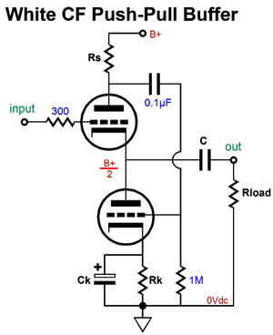
Before leaving this section, I should show an all-tube design.
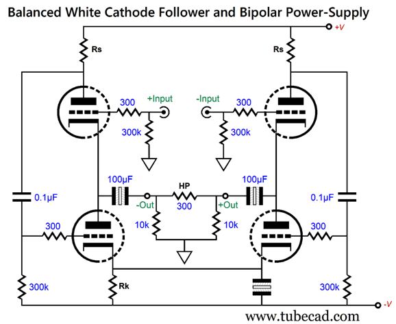
The White cathode follower is a push-pull version of the cathode follower that is similar to the SRPP and SRCFPP in that it must be optimized for specific external load impedance. We can easily arrange two White cathode followers with a monopolar power supply to achieve a balanced output. The problem is that the output-coupling capacitors must be twice the value of non-balanced buffer, as the load impedance is effectively halved in the balanced configuration. One workaround is to use non-polarized electrolytic capacitors, which sound vastly better than normal polarized electrolytic capacitors; but we then run into the lower voltage limits of most non-polarized electrolytic capacitors. In addition, we must use two input coupling capacitors. In contrast, by using two balanced White cathode followers with a bipolar power supply, we can get away with low-voltage, non-polarized electrolytic capacitors; indeed, we can eliminate the need for any input coupling capacitor.
The current-sense resistor, Rs, can be found with the following formula: Rs = (rp + Rload)/mu Where rp is the triode plate resistance; Rload, the headphone impedance; and mu, the triode amplification factor. Since the headphone driver is an intrinsically differential device, the PSRR is excellent, as whatever power-supply noise leaks out of the two outputs will be equal in amplitude and phase, thereby completely ignored by the headphones. In order to see many more balanced White cathode-follower circuit ideas, see post 462 and post 559.
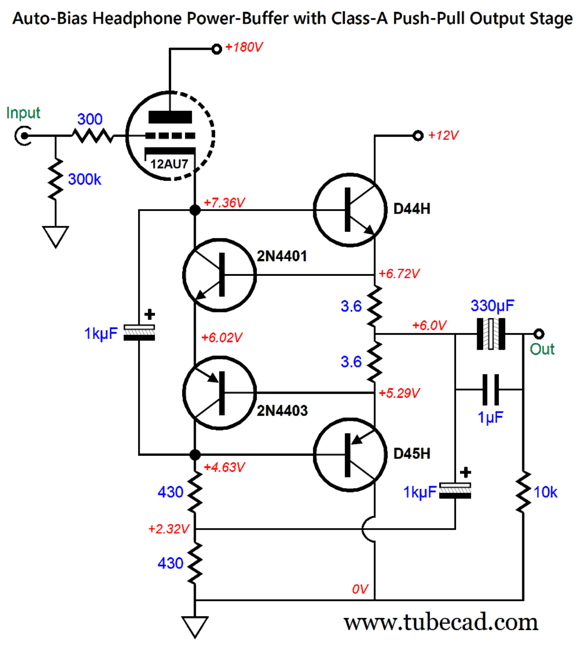
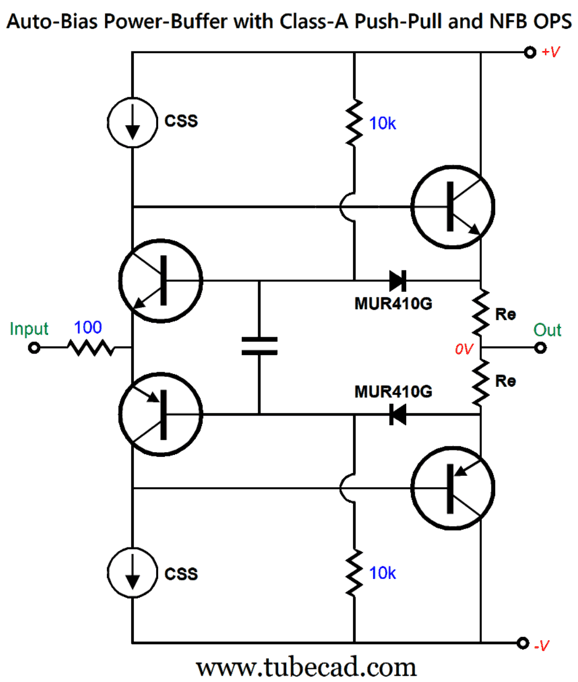
Auto-Bias Power-Buffer with Class-A Push-Pull and NFB OPS
A different sort of buffer can be made along the same auto-bias lines, except that we drive the input transistor emitters.
The input transistors not only auto-bias the class-A output stage, they provide AC negative feedback. The MUR410G rectifiers present a lower turn-on voltage than the input transistors' base-to-emitter turn-on voltage. This is critical, as the difference between these voltages is what appears across the output transistors' Re emitter resistors. I went searching through my vast number of SPICE circuits to find a workable example.
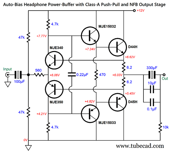
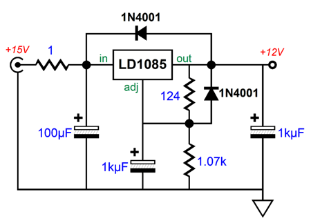
This unity-gain power buffer runs off a monopolar 12Vdc power supply. I assumed a wallwart switcher power supply, but we could get extra fancy and use a regulated linear power supply. Or we could add a linear 12V regulator to a 15V switching power supply.
The passive input RC low-pass filter will help scrub away switching noise before the LD1085 (or LD1084) regulator sees any of it. One way to view the buffer is that it effectively consists of two negative feedback loops and two in-phase outputs.
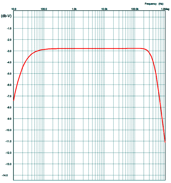
I ran some SPICE simulations on the buffer circuit and was pleased by the results. The frequency plot working into a 32-ohm load resistance was flat within 3db from 20Hz to over 200kHz.
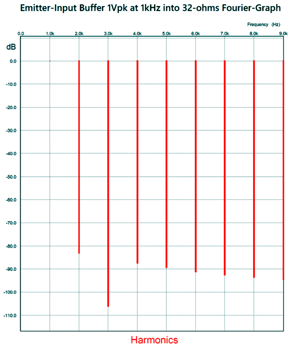
The Fourier graph of harmonics was equally impressive.
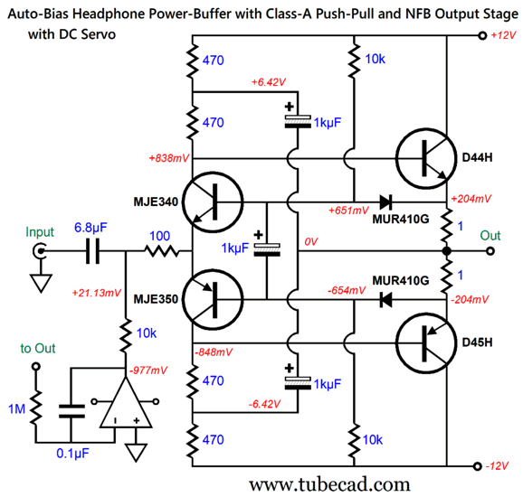
I love the greatly reduced 3rd harmonic and the smooth downward cascade of harmonics. I wondered how well a version with a bipolar power supply and no output coupling capacitor would work, so I devised the following variation.
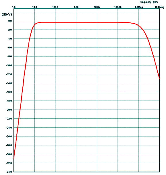
I was going to add two constant-current sources, but decided to try the simpler bootstrapped arrangement instead. The input is still capacitor coupled, and the DC servo ensures no DC offset at the output. The 6.8µF input coupling capacitor value was not arbitrarily chosen, as this value proved the optimal in SPICE simulations. The output emitter resistors were reduced to 1 ohm, which bring the output stage idle current to 200mA, which in turn implies a maximum class-A output-current swing of 400mA—plenty, even with 25-ohm headphones and 8Vpk output swings. In addition, the auto-bias feature worked as promised. The SPICE-produced frequency plotline was impressive.
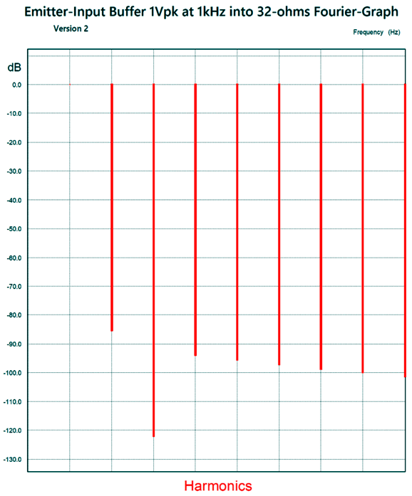
Note that the graph begins at 1Hz, not 10Hz; and that it ends at 10MHz, not 1MHz. The high-frequency extension was greatly furthered by having only two stages in the buffer. In the previous design, a higher-resistance input resistor was needed to quell high-frequency peaking. The Fourier graph especially impressed me.
Once again, we see the amazing notching out of the offensive 3rd harmonic. Put in terms of THD, the distortion is below 0.01%. The output impedance is about 0.5 ohms. If we desire balanced output, we need only double the number of buffers. Why would so powerful a unity-gain buffer be needed? Well, it's always good to hold some excess potential power in reserve. Moreover, there are a few very-inefficient planar headphones out there that eagerly eat up 8Vpk of output voltage swing.
Music Recommendation:
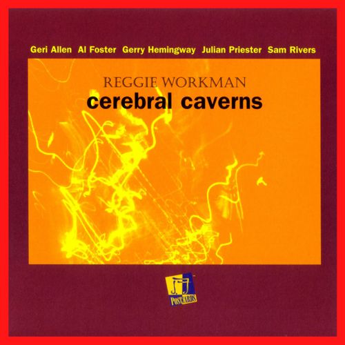
Reggie Workman's Cerebral Caverns
The result is a widely varying array of tracks—all of which sound great. Yes, this is the sort of album that audiophiles like, as it allows us to showcase our stereo systems. (When is the last time you heard a plucked piano string or tablas in a jazz album?) Wikipedia informs us:
I have only listen to it once, but I expect give it a few more spins soon.
//JRB
User Guides for GlassWare Software
For those of you who still have old computers running Windows XP (32-bit) or any other Windows 32-bit OS, I have setup the download availability of my old old standards: Tube CAD, SE Amp CAD, and Audio Gadgets. The downloads are at the GlassWare-Yahoo store and the price is only $9.95 for each program. http://glass-ware.stores.yahoo.net/adsoffromgla.html So many have asked that I had to do it. WARNING: THESE THREE PROGRAMS WILL NOT RUN UNDER VISTA 64-Bit or WINDOWS 7, 8, 10, and 11 if the OS is not 32-bit or if the OS is 64-bit. I do plan on remaking all of these programs into 64-bit versions, but it will be a huge ordeal, as programming requires vast chunks of noise-free time, something very rare with children running about. Ideally, I would love to come out with versions that run on iPads and Android-OS tablets.
|
I know that some readers wish to avoid Patreon, so here is a PayPal donate button instead. Thanks. John Broskie
John Gives
Special Thanks to the Special 83 To all my patrons, all 83 of them, thank you all again. I want to especially thank
All of your support makes a big difference. I would love to arrive at the point where creating my posts was my top priority of the day, not something that I have to steal time from other obligations to do. The more support I get, the higher up these posts move up in deserving attention.
If you have been reading my posts, you know that my lifetime goal is reaching post number one thousand. I have 414 more to go. My second goal is to gather 100 patrons. I have 18 patrons to go. Help me get there.
Only $9.95
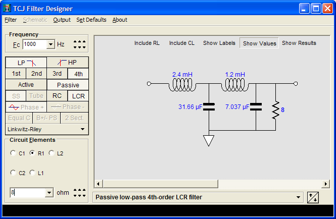
The Tube CAD Journal's first companion program, TCJ Filter Design lets you design a filter or crossover (passive, OpAmp or tube) without having to check out thick textbooks from the library and without having to breakout the scientific calculator. This program's goal is to provide a quick and easy display not only of the frequency response, but also of the resistor and capacitor values for a passive and active filters and crossovers. TCJ Filter Design is easy to use, but not lightweight, holding over 60 different filter topologies and up to four filter alignments: While the program's main concern is active filters, solid-state and tube, it also does passive filters. In fact, it can be used to calculate passive crossovers for use with speakers by entering 8 ohms as the terminating resistance. Click on the image below to see the full screen capture.
Tube crossovers are a major part of this program; both buffered and un-buffered tube based filters along with mono-polar and bipolar power supply topologies are covered. Available on a CD-ROM and a downloadable version (4 Megabytes). Download or CD ROM
|
|||


| www.tubecad.com Copyright © 1999-2023 GlassWare All Rights Reserved |