06 December 2023 Post Number 591

Some problems are so pervasive that they cannot be perceived. Here is an example: absolute phase. Other than a few audiophiles, few ever think about whether the music they hear leaving the car's speakers or their phone or their home theater system or the $130,000 loudspeakers in an audio showroom is in the correct phase relative to the sound that entered the microphones at the recording studio. Does it matter? Not to most listeners. Inverted phase makes no difference to frequency response, THD, dynamic range, or to SNR. Phasing did, however, matter to radio stations 80 years ago. Why?
Those radio transmitters would peak asymmetrically higher output power in one polarity than in the other. This same feature also often holds true for single-ended audio power amplifiers, as the output tube [or solid-state device] can draw far more than twice the idle current flow, while it can only let go of current conduction down to none. This inherent current-conduction asymmetry produces asymmetrically higher output power in one polarity than in the other.
In other words, the transmitters could cleanly pass larger asymmetrical output signals than symmetrical sinewaves. Where do we find such asymmetrical signals? They abound. Pianos, violins, and trumpets, for example, produce asymmetrical soundwaves. In addition, speech can exhibit asymmetrical soundwaves.
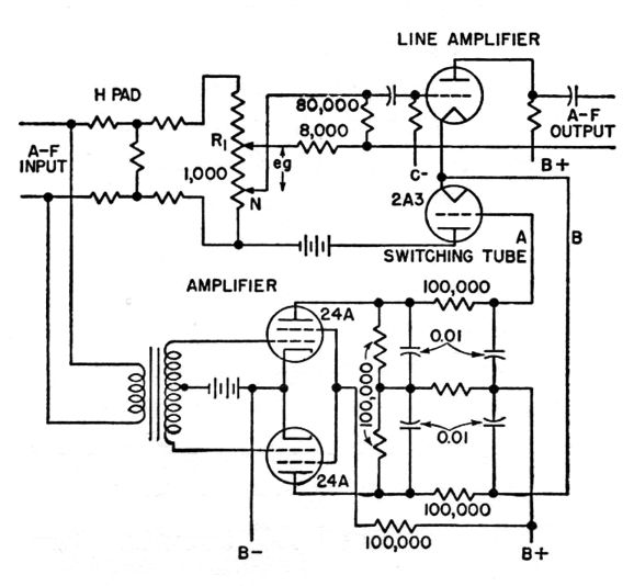
In the October, 1941 issue of Electronics magazine, we find on page 64 an article titled: "Automatic Phase reversal Amplifier." (The article is reproduced at the very bottom.)
When the circuit detects an asymmetrical signal, it switches the polarity of the output signal to deliver the most positive accrual of peak signal. Eventually, radio transmitters were developed that, much like push-pull audio power amplifiers, produced equal output swing in either polarity (in other words, symmetrically). Soon enough, the issue of absolute phase was forgotten.
For the last 60 years, a few audiophiles pointed out that absolute phase mattered, as they could hear the difference that flipping the polarity made, preferring the sound from one polarity over the other for some recordings but not others. I am sure that they could, as I have heard it many times myself. We were not alone, recording engineers heard it too; their near universal workaround was to flip the phase on every other track on an album, as that way we will hear the correct absolute phase 50% of the time.
See what I mean about this problem being so pervasive that few know it even exists, and those few who know, choose to ignore it, as it simply invites no easy remedy. Or does it? If your music playback comes from FM or LPs or tape, no easy solution can be had. Digitally stored music, on the other hand, offers the great advantage of being dead; the binary encoded signals are captured, sealed and delivered. In contrast, the three other signal source are alive, as the radio signal might falter, the LP might skip, the tape might wrinkle or stretch. These signals—in contrast to digital—live; being capable of change, they are not perfectly predictable. In contrast, the CD's one and zeros could be printed in a thick book or on a large tombstone.
Back in 1982, when the CD was introduced, things might have proceeded better if a few additions had been made. For example, each CD could have easily held a small text file that listed all the tracks and their time lengths; all the musicians and their instruments; the composers and the recording engineers; the recording equipment and microphones and studio used.
The staggeringly stupid mistake was not to have made allowances for mono recordings, which include most spoken word recordings. All that was needed was a digital marker so the CD player would know to read the one and zeros as belonging to a single mono channel, which would have doubled the CD potential playback time, as the CDs would spin at half their normal speed. By the way, CDs do not spin at a constant rotational speed, i.e. constant-angular velocity (CAV); instead, they spin at a constantly varying speed, i.e. constant-linear velocity (CLV). In other words, asking the CD to start spinning at half the normal speed is not much to ask.
Moreover, digital music files could have held a small, short sub-audible beginning pulse, either positive or negative, to mark the absolute polarity for each track. Thus, while the trick of flipping phase on every other track would persist, but for those who care, we could tackle the problem of setting the absolute-phase right for each track. For example, CD players and standalone DACs could read the pulse's polarity and flip the phase accordingly. We would then wire up our speakers to match the absolute phase, which might mean that we would invert the speaker cables, as the line-stage amplifier or power amplifier might have inverted the phase, so we needed to flip the cable connections to undo the phase reversal.
Sadly, the chance of a smarter designed CD is long gone. Today, we need a modern workaround. Since a huge library of already recorded music exists, a smart music streamer and DAC could sample the digital code and tabulate the predominance of positive peaks to negative peaks (and possibly take an accumulative RMS average), then not only flip the phase for the track, but also keep a database of the track and its relative phasing. Soon, the database entries would be shared with other likeminded audiophiles, much as Discogs.com displays user entered album data that the missing CD text file would have offered; thus, the data sampling would not be needed for popular albums, such as Dark Side of the Moon.
Okay, absolute phase is a yes-no sort of attribute, much like gender had been just ten years ago. But timing relations between two loudspeakers reproducing the same signal admit infinite differences, much like gender today. Soundwaves travel slow enough that we see the lightning well before we hear the thunder. Place one loudspeaker just one foot closer to you than its brother, and the stereo image will suffer. Sonic time discrepancies matter.
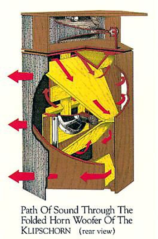
One particularly egregious example is the famous Klipsch corner horn. Touch a 1.5V battery to this speaker's input terminals and you will first hear the tweeter's contribution, a sharp clicking sound; then a little over one millisecond later, the midrange's output, a rounded click; then a staggering 10 milliseconds or so later, the woofers delayed output, a sluggish thud, as the woofer's output had to travel through many feet of labyrinth-like twisting path before leaving the enclosure and finally arriving at your ears. We talk about phase relationships of steady sinewaves, but the real issue here is musical sounds time delay. The corner horn might measure flat, in terms of frequency response, as the testing used steady sinewaves, which are blind to timing differences. For example, we could place the midrange horn ten feet out from the corner bass horn and the tweeter out a further ten feet from the midrange, we still might measure a flat frequency response from 40 feet from the corner, although music reproduction would be horribly garbled.
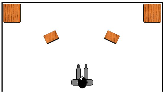
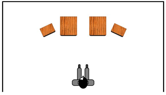
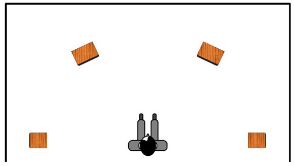
Here is another example, subwoofers and satellite loudspeakers. Some argue, quite convincingly, that the best location for subwoofers is in the room corners, as that location allows the development of the deepest bass and tightest coupling of the subwoofer's driver with the air in the room. Great, but then we face the problem of the satellite loudspeakers not time aligning with the subwoofers, unless they, too, sit in the corners.
Each foot of separation equals, roughly, one millisecond of sonic time delay. Experiments back in the 1930s, when "talkies" (movies with sound) were introduced, found that as long as the delay between woofer and tweeter was less than 3 milliseconds (roughly three feet), movie goers didn't complain about hearing double taps from the tap-shoes and double blasts from pistols.
We often are told that the subwoofers do not mate well with smaller loudspeakers because the subwoofers are too slow. What can "slow" mean? Subwoofer are not super-tweeter replacements; they are simply meant to produce the lowest frequencies. Perhaps, the issue isn't slowness, but tardiness. The ear hears the subwoofer lagging behind the main loudspeakers and bestows the epitaph of "slow."
Thus, in terms of timing, the preferred arrangement is the following.
The time alignment is better, but the spouse-acceptance factor diminishes. I have seen audiophiles place their listening chair in between two subwoofers, using the subwoofer cabinets as end tables.
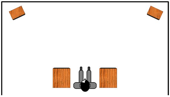
With the subwoofers in the room corners, the bass lagged behind the mids and highs; but in this arrangement, the bass leads. The result is much like hearing the thunder first, then seeing the lightning flash. (Do audiophiles in this situation complain that the subwoofers sound too "fast" or the main loudspeakers too slow?)
The workaround is to send the subwoofer amplifiers and the satellite loudspeaker amplifiers differently timed signals. When the subwoofers sit in the room corners, they get the music signal first; when used as end tables, last. Even when the subwoofers sit next to the main loudspeakers, small timing differences can occur as the subwoofer driver might fire downwards to the floor, while the main loudspeakers sit upon tall stands, so its path to our ears is shorter than the subwoofer driver's path. Fine adjustment is needed.
Therefore, what the audio world needs is a DAC with two sets of stereo DACs, with one set of DACs allowing either delay or advancement relative to the other DAC.
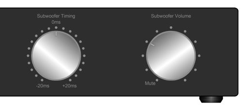
If we assume a worst-case time discrepancy of 20 milliseconds, advanced or retarded, then the DAC would hold the incoming digital stream in RAM memory for up to a 20 milliseconds delay. Would such a setup double or triple the cost of the DAC? Probably the first high-end audio DACs would sport vertiginously high price tags, but soon enough the price would fall. Let's be frank here: the cost of the fancy milled metal knob that sets the time delay could easily cost more than the expense of doubling up on DAC chips. For example, the highly esteemed ESS Technology SABRE9006AS 8-channel DAC cost less than $5; the two-channel AK4497 even less. True, the AKM AK4499EXEQ stereo DAC cost about ten times more, but I would argue that the subwoofer-output DAC does not need to be as fancy as the main-output DAC. Think about it: the old, old, Philips' 1985 TDA1541 DAC chip produced lovely bass. Indeed, with 100Hz as a common crossover frequency between subwoofers and main loudspeakers, 192kHz sampling rate seems to be a bit of overkill to faithfully reproduce a 40Hz signal.
By the way, a timing knob isn't essential, as up and down buttons would work just as well. In fact, all of the settings could be done with a smartphone app that uses the phone microphone to sample the subwoofer and main loudspeaker outputs and bring them into time alignment.
How would we set the correct time alignment the old-fashioned way? We could fiddle the knob until we liked the sound emerging. Or, we could use a test frequency set to the crossover frequency between the subwoofer and main speakers, say 100Hz. Then, we would flip the speaker leads on the main speakers and tune for the deepest null in sound. Afterwards, we return the speaker wires to the right polarity. (Of course, the DAC could hold an internal frequency generator and phase flipper circuits.)
Imagine hearing a bi-amplified Klipsch corner horn with time-aligned woofer and midrange. An actual stereo image would pour forth!
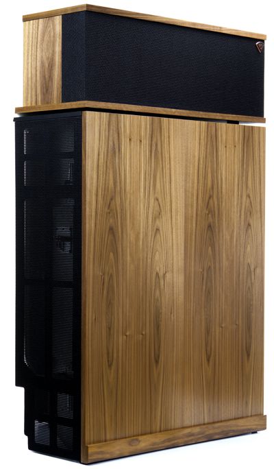
As I see it, Klipsch should make the standalone DAC with the preset time alignment and with built-in active crossover filters. Hell, they could even include the two power amplifiers (20W amplifiers are sufficient) and WiFi and/or Bluetooth circuitry needed to create a wireless corner horn—amazingly enough, the cost might be less than what they are spending on the passive crossover parts.
For almost four decades now, I have listened to headphones with subwoofer assistance, as I miss the somatosensation shock of deep ass-kicking bass when listening to headphones alone. Obviously, the sound leaving my headphones hits my ears far sooner than that leaving the subwoofers many feet away. Well, my two-DAC, time-adjustable solution would make for even better headphone listening. An additional use would be to feed rear loudspeakers a time-delayed signal.
If you have never tried this setup, you are missing an excellent sonic experience. I found that small two-way loudspeaker placed behind me and facing the walls produce a subtle enhancement of room acoustics. The secret is to raise their sound level just up to where you can barely hear them. Listen to them for a few days and prepare yourself for the profound disappointment when you turn off the rear power amplifiers. Thin, meager, and pinched sound emerges from your previously highly esteemed front loudspeakers. In addition, you will find that much less sound volume is needed with this arrangement compared to just front loudspeakers, which your family and neighbors will appreciate.
DC servos use an OpAmp, capacitor, and resistor to form an integrator circuit. An integrator circuit performs the analogous electrical function to the mathematical operation of Integration, which is the process of adding or summing up the parts to find the total. It is one of the two fundamental procedures of calculus, the other being differentiation. Since the OpAmp is configured in the inverting arrangement, it delivers at its output the negative integral of the input voltage. If your head hurts, do not worry, as you do not need to understand calculus to see how a DC servo works.
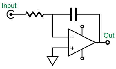
If fed an input signal of square-waves, the integrator's output signal is a triangular sawtooth, the result of the capacitor charging up and discharging. An integrator circuit becomes a DC servo circuit when it is encompassed inside a negative feedback loop. Here is a super simple example:
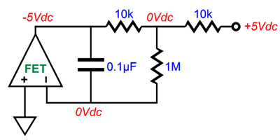
An OpAmp strives to see the same voltage at both its inputs at all times. Since its non-inverting input is grounded, its inverting input must also see 0V. When we first attach the +5Vdc voltage source, the 1M resistor will relay this positive voltage to the inverting input, which prompts the OpAmp's output to swing negatively until the output reaches -5Vdc, thereby creating a voltage null at the nexus of all three resistors. Without the capacitor, the OpAmp's output swings instantly negative. The capacitor slows the negative swing. The larger the capacitor is in value, the slower the response, as the capacitor must charge up. The -3dB transition frequency the 0.1µF capacitor and 1M resistor is 1.59Hz, which is well below the typical 20Hz cutoff for audio gear.
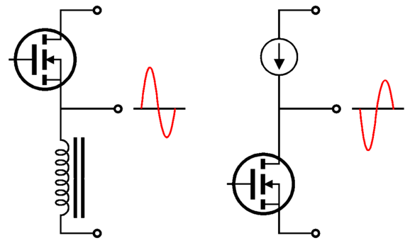
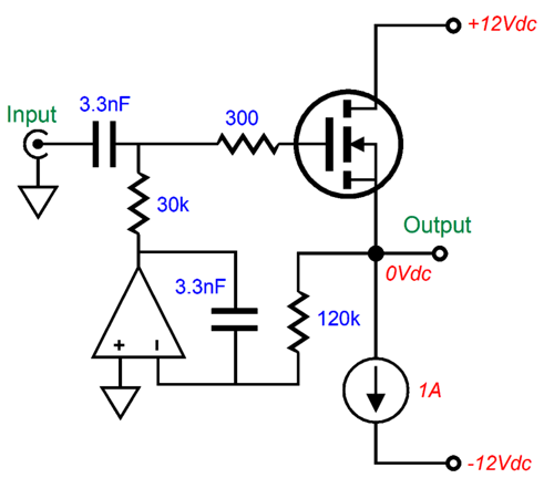
Let's move on to a FET-based unity-gain buffer circuit.
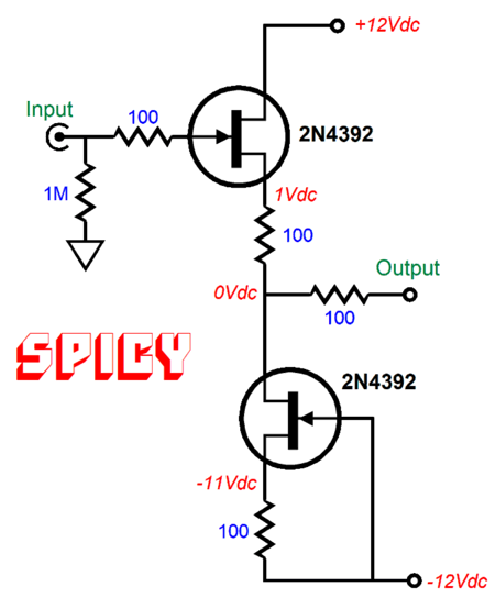
In the world of SPICE simulation, this circuit works perfectly—well, at least in terms of output DC offset, as both FETs are perfectly matched, as are both 100-ohm resistors. Reality differs. Even a mismatch of only 1% will prompt a DC offset. Adding the "tugging" DC servo (shown beforehand) eliminates DC offsets—within reason.
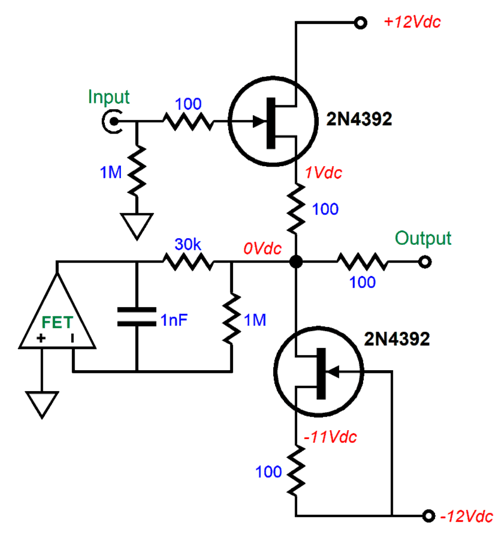
The DC servo tugs the buffer's output back to zero DC offset. The assumption here is that the OpAmp holds a FET input stage and that the OpAmp runs off the ±12Vdc power-supply rails. Assuming that the OpAmp can swing ±12Vpk of output voltage, the 30k resistor allows up to a third of a milliamp of current. In other words, matched FET should still be used. Note the relatively small value for the capacitor, just 1nF (i.e. 0.001µF). The DC servo imposes a high-pass filter function on the buffer's output. In this example, the -3dB transition frequency is 0.8Hz! Our electronic experience and intuition argues that with the 1M resistor and 1nF capacitor the transition frequency should be 159Hz, which is 200 times higher. What went wrong? Or, rather, what went right? How did we get away with a smaller capacitor value? The answer is simple, but a headscratcher nonetheless.
The 30k resistor is effectively defining a two-resistor voltage divider with the buffer's output impedance, which in this example is 150 ohms. Therefore, the OpAmp's output voltage is effectively reduced by 30k/150 or 200, which in turn effectively increases the 1M resistor's value by 200 times. By the way, the high-pass filter's function is 1st-order, 20dB per decade, 6dB per octave.
Missing from the DC servo (and all future DC servo schematics) are two protection diodes.
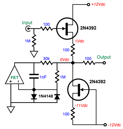
The 1N4148 signal diodes are ultra-fast and limit the maximum voltage differential between the two OpAmp inputs to about ±0.7Vpk. We now inch our way to a more familiar arrangement.
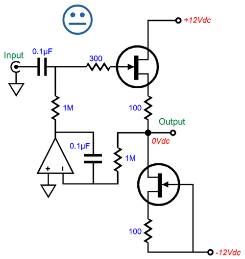
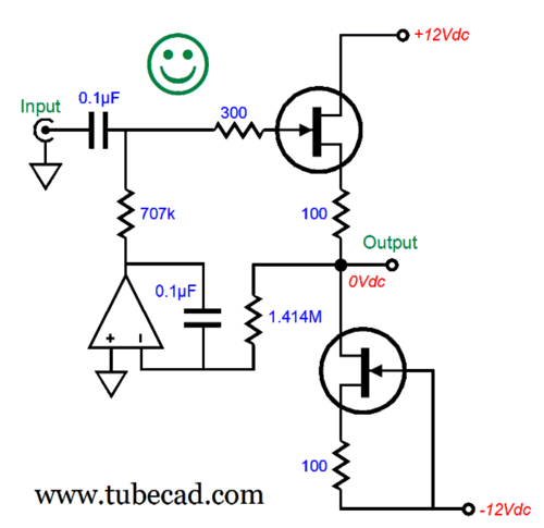
With the addition of the input coupling capacitor, the DC servo no longer has to provide output current, only output voltage, as the FET's gate input presents a near-infinitely-high input impedance. (A NPN transistor, in contrast, does require some base current flow.) Huge imbalances between FETs can be overcome by this DC servo.
Everyone knows that the input coupling capacitor will force a high-pass filter function on the buffer, but few realize that the DC servo also imparts its own 1st-order high-pass filter action, making a combined 2nd-order high-pass filter. In this example, a -3dB transition frequency of 1.59Hz, due to the 0.1µF capacitor and 1M resistor; with such a low-frequency cutoff, it's quite easy to ignore the DC servo's frequency-selective behavior. The missing happy face icon is due to the 2nd-order high-pass filter's Q of 1, which implies some peaking at the transition frequency. The workaround is to skew either the capacitor or the resistor values by a 0.707:1.414 ratio, which simplified equals a 1:2 ratio.
The transition frequency remains unaltered, but the Q has been reduced to 0.707, making this a Butterworth alignment, whose output is -3dB down at the transition frequency. Here is a variation with skewed capacitor values.
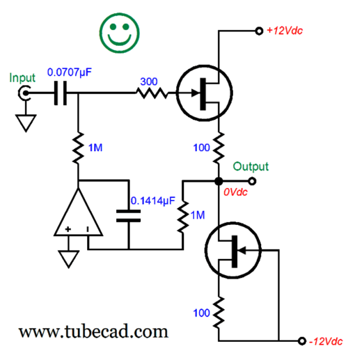
This variation, which skews the capacitor values, yields the exact same results as the previous version. Mind you, resistors come in a vast array of values, whereas capacitors don't. In other words, first find tight-tolerance capacitors, then seek the needed resistors.
Now things get interesting. If we skew the resistor values by a ratio of 0.5:2 (i.e. 1:4), we get a Linkwitz-Riley high-pass 2nd-order filter alignment.
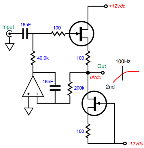
A capacitor value of 16nF and our desired crossover frequency of 100Hz imply a 100k resistor, based on the simple formula of Frequency = 1/2piCR or the preformatted formula that works with µF values: Frequency = 159155/C/R. We apply the 0.5 and 2 multipliers and get 50k and 200k. (The resistor values shown are close enough.)
By the way, there are times when we desire some peaking. Here is one possible example: our main loudspeakers use a sealed enclosure to load the woofer, with an Fc of 80Hz and Q of 0.3. Very thin bass results, as the loudspeaker will be down 10.5dB at 80Hz. Therefore a subwoofer is needed, which will get a 4th-order Linkwitz-Riley crossover at 80Hz. In other words, the loudspeaker's own intrinsic high-pass 2nd-order filtering will become part of the 4th-order filter. Q's multiply. A Q of 0.5 is required, so the active 2nd-order filter's Q must be 1.67 to bring the cascade of 2nd-order filters to a 4th-order Linkwitz-Riley high-pass filter. (The usual way we build an active 4th-order Linkwitz-Riley crossover filter is to cascade two 2nd-order Butterworth filters, as their Q of 0.707 multiplied against each other yields a Q of 0.5, as 0.707 ² = 0.5.) Okay, time to return to DC servos circuits.
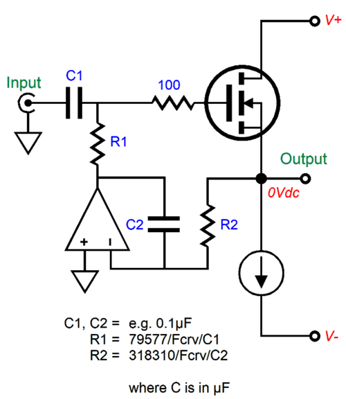
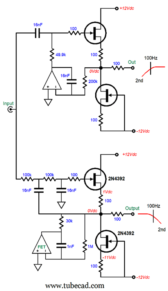
I switched to a MOSFET-based power buffer to show that the use of a DC servo as a Linkwitz-Riley crossover filter is not limited to FETs. For example, let's say you are building bi-amped loudspeaker system that uses a horn midrange and tweeter. The following power unity-gain buffer can deliver 4W into 8-ohm loads. Its crossover frequency is 800Hz with a Linkwitz-Riley 2nd-order alignment.
Okay, let's now scale up to a more powerful unity-gain buffer.
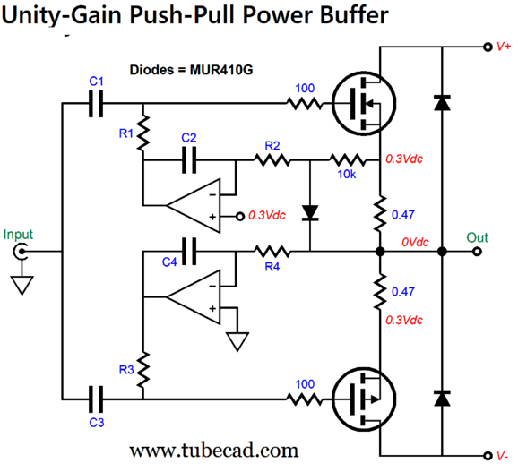
Two OpAmps are needed. The OpAmp sets the idle current flow. To find the idle current we divide 0.3V by the source resistor value; in this example, 0.3/0.47 equals 0.64A. If we use 0.3-ohm source resistors, and if we run ±20Vdc bipolar power-supply rail voltages, the power buffer would put out 16W of class-A power into 8-ohm loads. The MUR410G rectifier limits the DC voltage monitored across the source resistor to 0.6Vpk relative to the output. Why?
The diode and 10k resistor act as a clipping circuit. While a big sinewave can leave the buffer's output, the clipping circuit delivers a square-wave to the idle-setting DC servo. This is a safety circuit of sorts; if the buffer never leaves its strict class-A window of current conduction, neither the diode nor 10k resistor are needed. In the real world, however, we can expect the output current flow to exceed the class-A limits; which absent the diode and 10k resistor, the DC servo would see too great a voltage and would drop the bias voltage excessively, possibly transforming a class-A output stage into a class-C one, wherein both output devices completely cutoff at idle. Not good.
The bottom OpAmp works as a DC servo to eliminate any DC offset voltage at the output. If the output DC voltage strays positively, the OpAmp's output voltage will swing more negative, thereby increasing the bottom MOSFET's current conduction, which in turn will pull the output back to 0V at idle. Conversely, if the output slides into a negative DC voltage, the OpAmp will lower the bottom MOSFET's current conduction, allowing the top MOSFET to pull the output voltage back to 0Vdc.
By following the math shown for the FET-based buffer, we can impose a high-pass Linkwitz-Riley crossover filter on this power buffer.
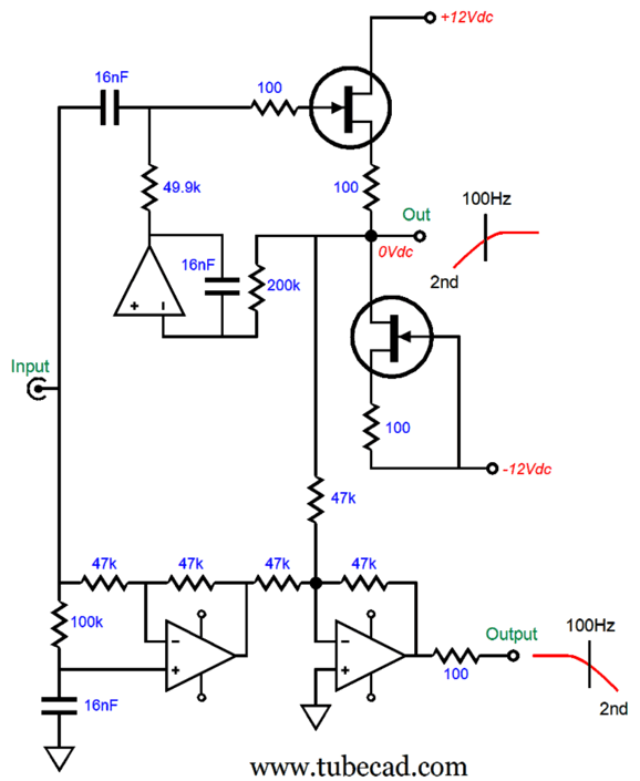
We can get fancier still, as we can transform the clipping portion of the circuit into doing double use by it also creating a constant-transconductance output stage.
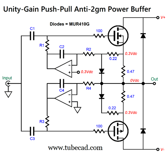
The 10k resistor has been replaced by a 0.22-ohm resistor and the clipping circuit has been duplicated. When the output stage swings sufficient current into the loudspeaker to cut off one MOSFET, the still conducting MOSFET will see its diode becoming forward biased, so its source resistor will be shunted by the diode in series with the 0.22 resistor, thereby effectively doubling the MOSFET's transconductance.
I know that many have zero interest in an anti-2gm output stage. As they see it, no one cares about it so why should they. The thing is most of these detractors do care. How so? They love single-ended and class-A amplifiers, both of which hold constant-transconductance output stages. The following graph shows the SPICE-generated Fourier graph for this ant-2gm output stage at full output (36W at 10kHz into 8 ohms).
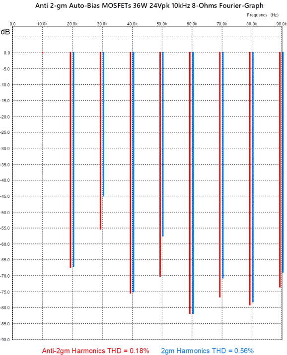
With the diodes and 0.22-ohm resistors, the 3rd and 5th harmonics fall by more than 10dB. In fact, other than the 9th harmonic, all the harmonics are lower with the ant-2gm arrangement, resulting in a threefold improvement in THD. (Bear in mind that at 1kHz, the distortion would be even lower, as the MOSFET's high input capacitance imposes hardships at high-frequencies.) Here is the graph for 1W of output.
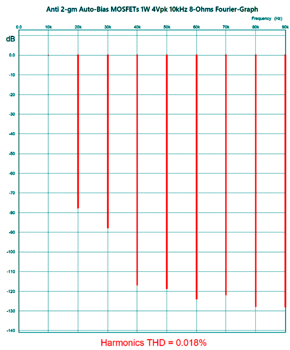
Do not forget that this is a negative-feedback-free output stage. Had the output stage been enclosed in a global negative feedback loop, the distortion would be lower still. We can use more output MOSFETs, so as to spread the heat dissipation.
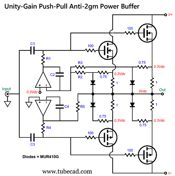
Note that resistors R2 and R3 are effectively in parallel; for example, two 1M resistors would yield 500k of resistance. Ideally tightly matched MOSFETs would be used throughout, but this doubled-resistor arrangement will average for us the two source-resistor voltage drops. Also, note that the source resistor values are now 1 ohm and the accompanying anti-2gm resistors are 0.75 ohms. The diode's effective dynamic series resistance is about 0.2 ohms, which must be added to the anti-2gm resistor value. The output impedance for this output stage is about 0.25 ohms, which implies a damping factor of 320 with an 8-ohm loudspeaker. (Mind you, many tube-based single-ended power amplifiers present 2-ohms or more of output impedance.)
With 1-ohm source resistors, each MOSFET draws 300mA of current at idle. Use a total of eight output MOSFETs, and the total idle current climbs to 1.2A, which implies 23W of class-A power into 8-ohm loudspeakers. In such an arrangement, the peak output current swing equals 2.4A, which implies an output voltage swing of 19.2V. With a ±22Vdc bipolar power supply, the output stage dissipation at idle would be 52.8W, which implies an efficiency of 44%, 6% less than the theoretical 50% maximum. Since this would be a true class-A output stage, the output devices will cool as power is delivered into the load.
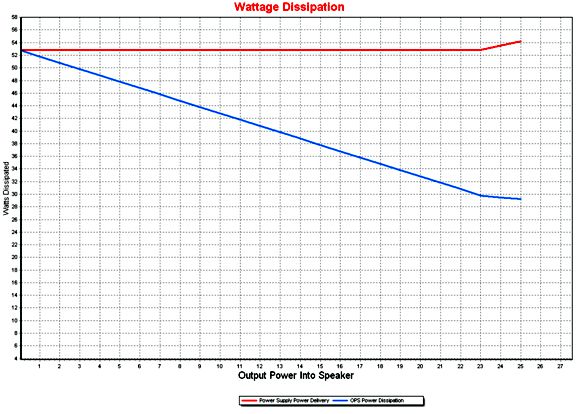
Up to the point where the class-A window of output power is still observed, the power supply delivers a constant amount of power. Once the output exceeds the class-A window's limit, however, the power-supply delivery increases. What if we attach a 4-ohm loudspeaker? The class-A amount of power falls to 11.5W. (If an output transformer were used with a 4-ohm output tap, then the power output would be 23W.)
A quick side trip: I have seen class-A amplifier specifications that state the power output is 36W into 8-ohm loudspeakers, but 72W into 4-ohm speakers. True enough, as far as measured power output is concerned, but the amplifier might only deliver 18W of class-A power into the 4-ohm load. The minimum idle current flow for a direct-coupled push-pull class-A amplifier is 1.5A, as a peak output current swing of 3A is needed to deliver 36W into 8 ohms. In contrast, 3Apk into a 4-ohm load only equals 18W, as 3² x Rload/2 = 18. Remember, class-A operation is not voltage but current dependent. All class-AB amplifiers will put out some class-A power; given a sufficiently-high load impedance, all the output will be class-A, as none of the output devices ever cease to conduct. Now, it's possible that the class-A amplifier's idle current is a healthy 3A, which could deliver the needed 6A peak current to deliver 72W class-A watts into a 4-ohm load; but the amplifier would have to dissipate at least 144W at idle, which is an insane amount for a nominally 36W power amplifier.
Let's look at the power buffer's dissipation with a 4-ohm load.
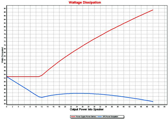
Note that the maximum power output climbs to 50W in class-AB mode, but stops at 11.5W in class-A mode.
Since the power buffer is a unity-gain circuit, how do we drive it to full output? A tube-based line-stage amplifier with a gain of 26dB could drive this feedback-free output stage to full output, as long as the line-stage can deliver enough current to overcome the high input capacitance presented by the MOSFETs (SiC MOSFETs, in contrast, present far less capacitance).
Okay, let's return to something simpler: a two-way active Linkwitz-Riley crossover for use with subwoofers.
The bottom 2nd-order low-pass filter is based on the Salen-Key topology and uses the tugging DC-servo arrangement. The tugging DC servo not only eliminates a DC offset due to mismatched FETs, it will also eliminate small DC offset voltages at the input. Remember, this tugging servo imposes a 1st-order high-pass filter on the output signal, albeit at a very low 0.8Hz. With a crossover frequency of only 100Hz, many might be willing to let the low-pass filter be handled by OpAmps.
Bear in mind, this low-pass filter will pass along any DC offset voltage present on the input signal; adding an input coupling capacitor is not a bad idea. This arrangement saves one capacitor, which can prove decisive when using $100 fancy capacitors. If the low-pass filter makes no sense to you, it's only because you haven’t read post 563. In that post, you would have seen the following circuit:
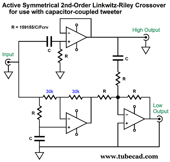
The idea behind this design was that an active two-way, 2nd-order Linkwitz-Riley crossover could be made that held a 14-pin DIP socket on its PCB, which would allow us to plug in 7-resistor array chips to set the crossover frequency for both stereo channels at once. All three capacitors must be the same value, and the 1% chip array of resistors determines the crossover frequency. In other words, only the resistors marked with "R" need to change in value. (If I had any brains, I would make and offer the PCB for this circuit. Three dual-OpAmps could be used, with the one used for the high-frequency filter being the fancy super-fast type, while the bass filters would get slower, but more stable OpAmps.)

In my vast jazz collection, only one CD from Chris Botti could be found, To Love Again, a gift not a purchase. I wasn't impressed, as I thought it cleaved too close to easy-listening jazz. In addition, I was prejudiced against Botti, as I saw him as a young pretty-boy jazz musician. Well, he is no longer young or so pretty, so I gave his latest album, Vol 1., a listen. I am glad I did. If nothing else, the recording is excellent. Moreover, he can blow a mean trumpet.
All the song covers are jazz standards, such as "My Funny Valentine" and "Someday My Prince Will Come." This selection of jazz warhorses was a brave move on his part, as many jazz greats have lain down high-water markers. Amazingly enough, he didn't sink, but he held his own. This is an album that those who do not like jazz will like nevertheless. You can use it as pleasant background music or as serious jazz that warrants close attention. I look forward to hearing Vol 2.
Amazon Music offers its streaming in 24-bit, 96kHz.
//JRB
With the unsymmetrical wave forms that are characteristic of much speech and music, it is desirable in broadcast stations to have the peaks that have the greater magnitude modulate the carrier of the transmitter in the upward direction in order to permit the greatest possible coverage by the station without introducing distortion by overmodulation. The switching required for this can be achieved automatically with the circuit shown, which consists essentially of a normal line amplifier, a switching tube, and a push- pull amplifier whose function is to operate the switching tube in accordance with the polarity of the voltage at its output terminal.
First consider the operation of the line amplifier with the 2A3 switching tube and push-pull amplifier disconnected. The signal voltage across the input of the line amplifier is e g, and for the instantaneous voltages, as marked, the signal voltage at the grid will be negative with respect to that of the cathode. Now assume that the 2A3 switching tube is connected. For the moment we shall disregard the grid, or input, circuit and shall merely assume that plate current flows through this tube. The flow of plate current will set up a steady voltage across R1, which will give a somewhat more positive bias to the line amplifier, but the signal voltage will remain unchanged. Thus the effect is the same as if the bias control were at the top instead of at N, so far as the instantaneous voltage on the input of the line amplifier is concerned. The function of the push-pull amplifier is merely to provide a convenient and automatic switching arrangement for the 2A3 switching tube.
For zero signal on the input of the push- pull tubes, terminals A and B are at the same potential, and consequently the 2A3 tube has zero bias. When a signal voltage is applied, one of the terminals becomes negative with respect to the other. If terminal A is relatively negative, the 2A3 tube is biased to cutoff, since only a low voltage is used on the plate of the 2A3. This mechanism automatically reverses the circuit so that the higher peaks will always modulate the transmitter upward, although for proper operation the position of the terminals A and B may have to be reversed.
The input circuit of the two 24A tubes must be a transformer to obtain proper operation of the push-pull amplifier. It should be noted that the screen grid of these tubes is not at ground potential and that no bypass capacitor from screen to ground should be provided. The plate battery of the 2A3 tube should be as low a voltage as possible so that a small grid voltage will cause the tube to conduct current or to produce cutoff. The 24A tubes are biased approximately to cutoff. The H pad reduces the voltage to the tube and voltage-divider network so that switching is done at a low audio level.
R. P. Crosby, Automatic Phase Reversal Amplifier, Electronics, October, 1941, p. 64.
Did you enjoy my post? Do you want to see me make it to post 1,000? If so, think about supporting me at Patreon.

Just click on any of the above images to download a PDF of the user guides.
For those of you who still have old computers running Windows XP (32-bit) or any other Windows 32-bit OS, I have setup the download availability of my old old standards: Tube CAD, SE Amp CAD, and Audio Gadgets. The downloads are at the GlassWare-Yahoo store and the price is only $9.95 for each program.
http://glass-ware.stores.yahoo.net/adsoffromgla.html
So many have asked that I had to do it.
WARNING: THESE THREE PROGRAMS WILL NOT RUN UNDER VISTA 64-Bit or WINDOWS 7, 8, and 10 if the OS is not 32-bit or if it is a 64-bit OS.
I do plan on remaking all of these programs into 64-bit versions, but it will be a huge ordeal, as programming requires vast chunks of noise-free time, something very rare with children running about. Ideally, I would love to come out with versions that run on iPads and Android-OS tablets.
|
|
|
|
I know that some readers wish to avoid Patreon, so here is a PayPal button instead. Thanks.
John Broskie
John Gives
To all my patrons, all 85 of them, thank you all again. I want to especially thank
Concordio Anacleto
Walter Clay
King Heiple
Kuldeep
Amy D. McNeil
Paul Radovan
Christian Rintelen
Jason Stoddard
Kelvin Tyler
Dwight Warren
I am truly stunned and appreciative of their support. In addition I want to thank the following patrons:
John Atwood
Hal Clark
Dean Bailey
Jim Burnes
Eduardo Fayad
Scott Fraser
Manny Gagliano
Mike Galusha
Richard Hansen
Andreas Hierzenberger
Erik Hoel
Dean Kayser
Tom Kelly
Thomas Kifowit
Francis King
Frank Klapperich
Neil Kovacs
Przemek Lach
Robert
Ron Lee
偉良 林 (David Lin)
Amy D. McNeil
Csaba Molnar
Joe Mooney
John R. Murray
Seiichiro Nakakura
Larry Owens
John Puma
Paul Reid
Marty Reiss
Paulo Mario dos Santos Dias de Moraes
Blake Swaney
Michael Taylor
Brian Terrell
James Tiemann
Dwight Warren
Andrew White
Sergey Yegourno
All of your support makes a big difference. I would love to arrive at the point where creating my posts was my top priority of the day, not something that I have to steal time from other obligations to do. The more support I get, the higher up these posts move up in deserving attention.
If you have been reading my posts, you know that my lifetime goal is reaching post number one thousand. I have 409 more to go.
My second goal was to gather 1,000 patrons. Well, that no longer seems possible to me, so I will shoot for a mighty 100 instead. Thus, I have just 15 patrons to go.
Help me get there. Thanks.
Only $12.95
to keep track of your
tube and part collection
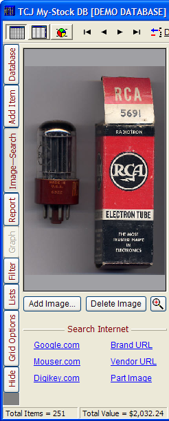
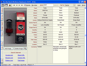
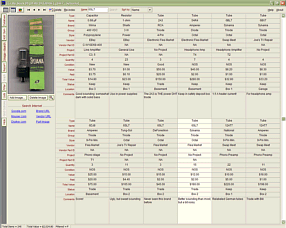
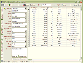
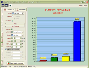
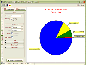
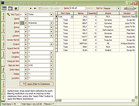
TCJ My-Stock DB
TCJ My-Stock DB helps you know just what you have, what it looks like, where it is, what it will be used for, and what it's worth. TCJ My-Stock DB helps you to keep track of your heap of electronic parts. More details.
List all of your parts in one DB.
Add part Images.
One-click web searches for part information.
Vertical and horizontal grids.*
Create reports as PDFs.*
Graphs added 2D/3D: pie & bar.*
More powerful DB search.
Help system added.
Editable drop-down lists for location, projects, brands, styles, vendors and more.
*User definable
For more information, please visit:
|