| John Broskie's Guide to Tube Circuit Analysis & Design |
13 March 2024 Post Number 599
Just one more post to hit number 600. Mercy. I thought 500 was next to impossible—hell, I thought 100 was. I wish had some idea what the topic will for the Big 600, but nothing has inspired me yet.
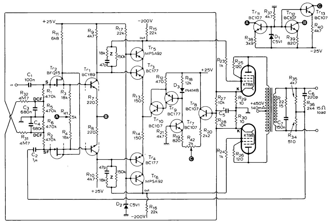
The Taming of the Chip Amplifier My introduction to a hybrid tube-solid-state power amplifier was in the April 1976 issue of Wireless World magazine, which detailed a solid-state frontend for a KT88-based output stage.
Seth Berglund's supremely clever design nonetheless disappointed me, as I longed to see the opposite—namely, a tube-based frontend driving a solid-state output stage. Soon enough, my wish came true, good and hard; thus, 17 years ago my coining the acronym DGNAOHA. My Post 291, written 10 years ago, elucidates DGNAOHA nicely:
This post goes on to list three essential attributes of a new hybrid amplifier design must hold to avoid the DGNNAHA label:
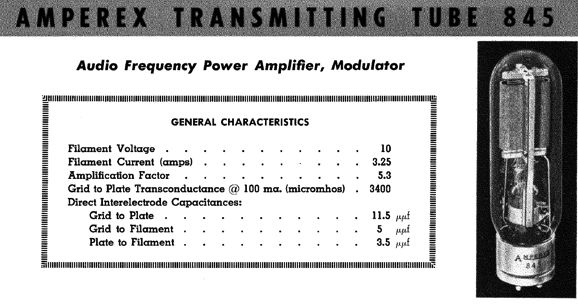
No doubt, very few will argue against restrictions 2 and 3, but some might argue in favor of violating numbers 1 and 4, if only to appeal to some aesthetical kink, which might delight in a hybrid power amplifier that uses an 845 transmitting tube, configured as a cathode follower, with a B+ voltage of 750V and a heater voltage of 10V and heater current conduction of 3.25A, 32.5W for the heater alone along with 50W of plate dissipation, all to drive an LM1875 to 20W of output.
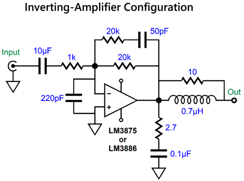
Such an amplifier would certainly qualify as weird, but possibly it might also be magnificently weird. My goal, however, is to abide by the four restrictions. Chip amplifiers, such as the LM1875, LM3875, and LM3886, perform better in the inverting configuration.
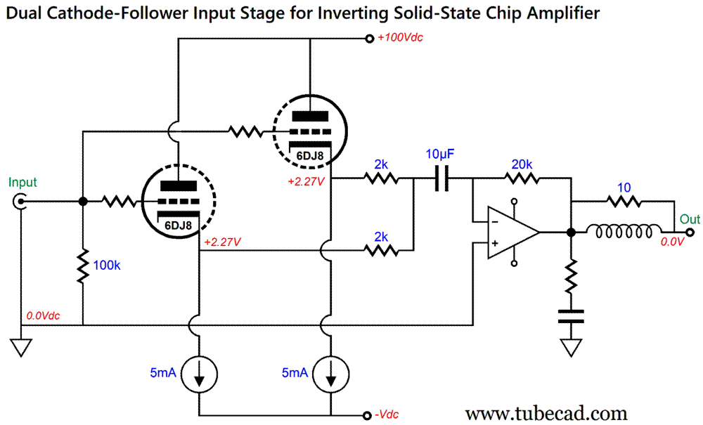
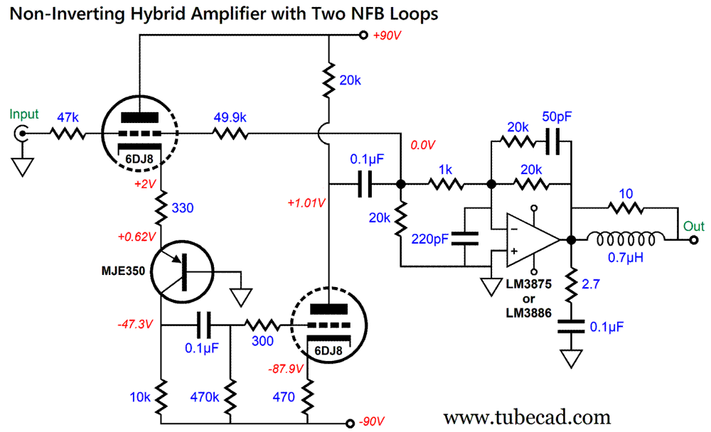
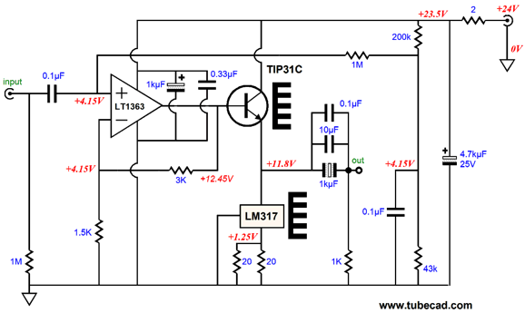
As Post 595 put it: "…most solid-state OpAmp and power amplifiers produce less distortion in the inverting configuration, as it reduces input stage common-mode distortion generation. Moreover, an inverting amplifier is less likely to suffer from positive feedback caused by the input signal being tainted by the output signal. If some mixing does happen, it just adds to the negative feedback. The supreme penalty we must pay, however, is a much-lower input impedance." Unfortunately, the LM3875 and LM3886 are nowhere near unity-gain stable, so we cannot replace the 1k negative feedback resistor with 4.7k resistor. No, we are stuck with the 1k resistor. A 1k input impedance is a tough load, which begs for an input buffer stage. A simple tube-based cathode follower seems the easy solution, but 1k is still a tough for the typical small audio tube, such as the 6SN7 or 12AU7. In addition, we must accept some insertion loss of signal, as no cathode follower delivers true unity-gain. What is needed is a high-transconductance triode, such as the 6DJ8. In fact, two are better than one.
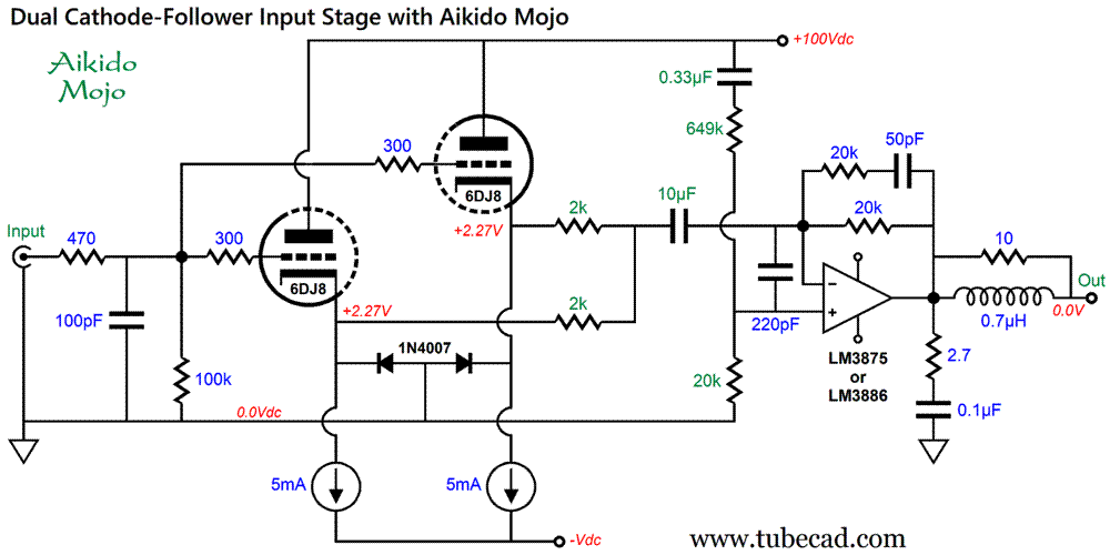
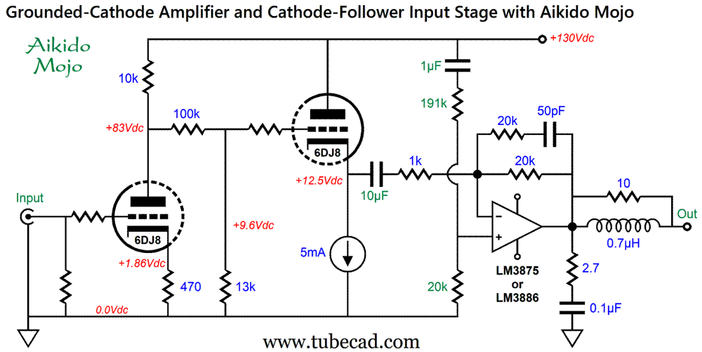
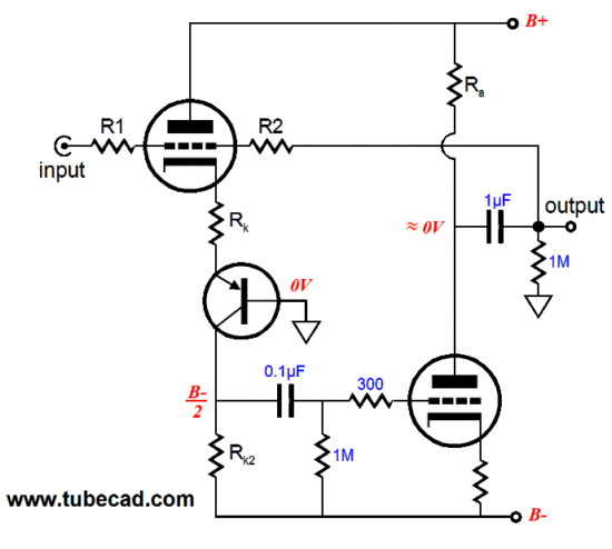
The two triodes both work into a 2k load, which effectively becomes 1k to the solid-state power amplifier. Actually, the solid-state chip amplifier realizes a signal gain slightly lower than the 1:20 (26dB) that its negative feedback resistors imply, as the two cathode followers do not achieve unity-gain output. In addition, each cathode follower presents an output impedance of about 100 ohms, which must be added to the 2k resistance, making 2.1k of total resistance. Why didn't I just tie the two cathodes together? It's far better to let each triode find its own cathode voltage. The two 5mA constant-current sources terminate into whatever is the negative power-supply rail voltage that the chip amplifier attaches to, usually between -25Vdc to -40Vdc. As it stands, this is not a bad arrangement, but it does raise two faults: the 6DJ8 triodes can be harmed at startup and the cathode followers will bleed 1/mu of the B+ voltage ripple at their outputs, where mu is the triode amplification factor. Do not forget that the chip amplifier develops a signal gain of 1:20 (+26dB), which will amplify the leaked ripple; thus, the real PSRR equation for the cathode follower is closer to 20/mu. Here are my workarounds to these two problems.
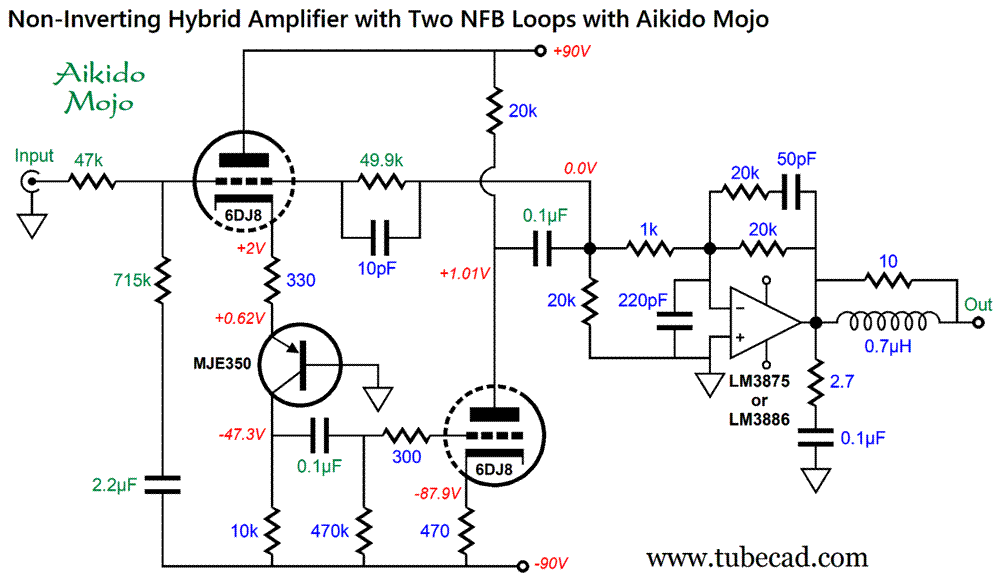
The two 1N4007 diodes are as protection diodes and only conduct at startup, when the triodes are cold and not conducting. Once the cathodes are hot enough to establish a cathode voltage above about -0.7V, the diodes are no longer forward biased and effectively drop out of the circuit. Without the protection diodes, the constant-current sources will pull the cathode voltages down to close to the negative power-supply rail voltage, thereby risking cathode stripping due the grid being so much more positive than the cold cathodes; the more negative the –Vdc voltage, the greater the potential damage. The Aikido mojo improves the PSRR substantially, as it counters the cathode followers' leaking of power-supply noise into the input signal passed on to the LM3886. In SPICE simulations, the PSRR for the tube frontend was -46dB, a -15dB improvement over stock cathode followers. Important: none of the green part values can be altered without requiring a reworking of all the other values in green. In other words, we cannot just grab any old film capacitor from our parts pin. This hybrid power amplifier is inverting, which is more of a feature than a bug. If the signal source is also inverting, then the two cancel, thereby transforming into non-inverting. If signal source is non-inverting, however, then you can flip the phasing of the loudspeaker cables, attaching the red-marked lead to ground, the black-marked wire to the output terminal. By the way, this circuit (and any other hybrid circuit) just begs for a two-stage turn-on of tube power supply first, solid-state power supply second. Indeed, a three-stage turn-on switch would be better still, as the heater should get the first flow of current, followed by the high-voltage B+ voltage, with the solid-state power amplifier bipolar power supply switching on last.
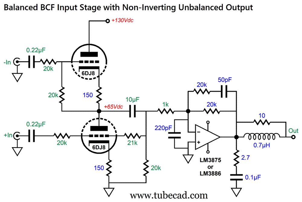
Broskie Cathode-Follower Input Stage
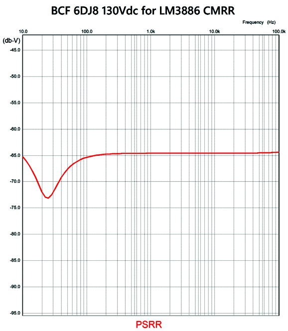
Once again, none of the green part values can be altered without requiring a reworking of all the other values in green. But this time, the goal isn't an enhanced PSRR, but an improved common-mode-rejection ratio (CMRR). CMRR is what balanced audio is all about. Ideally, only differences are acknowledged, and signals common to both inputs are ignored
I know that some are using 6DJ8-based BCF circuits to drive their 300-ohm headphones to several volts of output, so the 1k load impedance does not impose any undue hardship on the BCF, especially as only 1Vpk of output is needed.
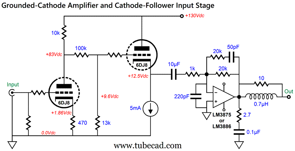
Grounded-Cathode Amplifier and Cathode-Follower Input Stage
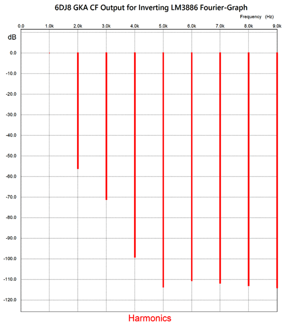
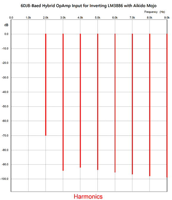
The 100k and 13k resistors form a two-resistor voltage divider that attenuates the input grounded cathode amplifier's output signal. The result is a unity-gain inverted output signal, which the solid-state power amplifier then inverts at its output. The cathode follower does face a 1k load impedance, but the cathode follower triode sees a larger cathode-to-plate voltage, which helps. What follows is the SPICE-generated graph of the Fourier breakdown of just the tube portion's output at 1Vpk at 1kHz.
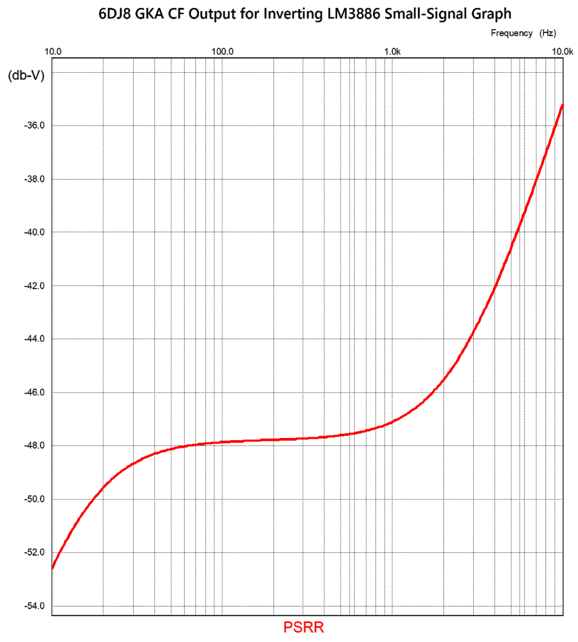
Note the lovely single-ended cascade of harmonics. What's not so lovely is the dismal -5dB PSRR for the tube frontend. The obvious workaround is either high-voltage regulation or massive chokes and big capacitors. The subtle workaround is to inject some Aikido mojo.
The three added parts improve the PSRR by over -40dB. Mind you, a clean B+ voltage is still required, but a -40dB improvement means a hundredfold reduction in leaked ripple. By the way, Aikido mojo PSRR enhancement does not grant us a license to be sloppy about the high-voltage B+ voltage, as some basic filtering is still required, say a simple RC filter. In other words, the Aikido mojo PSRR enhancement just improves upon an already good situation; we shouldn't expect it to perform miracles. Another by the way, the sonic signature of Aikido-mojo enhanced tube gear is not necessarily that of perceptually quieter operation, as the pre-enhanced gear might have been quiet enough to be largely ignored, but an enhanced resolution of micro details and such subtleties such as blacker blacks of silent passages and better perception of music hall dimensions and ambience.
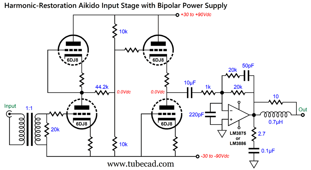
Aikido Fronted for Hybrid Amplifier
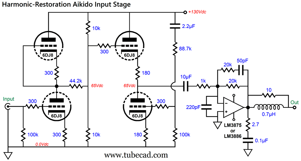
The two 10k resistors are effectively in parallel, so the 44.2k resistor is actually terminated into 5k of resistance, which seems to imply a tenfold decrease in signal amplitude. Missing from the calculation is the output impedance of the first stage, which in this example is about 6750 ohms. The two 10k resistors also leak 50% of the B+ voltage noise, which is what the input stage also leaks, so the math still holds for the Aikido cathode follower resistors. A good bit of harmonic restoration occurs due to the cascade of amplification first and then attenuation. In contrast, attenuation followed by amplification would not create the richer harmonic structure. See Post 592 for details on my experiment with harmonic restoration using the new 12Vac Aikido. What follows is radical Aikido variation. This Aikido breaks its direct connection to ground, yet retains the same excellent PSRR—assuming that the bipolar power supply rails exhibits the same amplitude of ripple but in opposite phase.
The top and bottom cathode resistors must match each other, as we are striving for balance. The input audio transformer is essential, as negative power-supply rail is polluted with ripple. With the input transformer, however, we sidestep the noisy negative power-supply rail noise, as the negative power-supply rail noise will be perfectly superimposed upon the input signal the bottom triode's grid sees. (If a triode's cathode and grid see the signal, they ignore it.) Since the top and bottom triode match each other, they form a two-resistor voltage divider to the bipolar power supply ripples, which being in anti-phase will cancel at the middle.
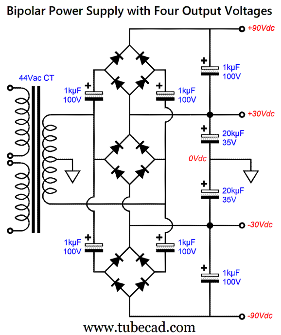
This arrangement might not look that appealing, especially as a good isolation audio transformer can easily cost $100. True enough, but an audio transformer can break ground loop problems that no other electronic means can approach. Moreover, the input transformer allows for balanced input signals and easy phase reversals. The best argument in favor of this variation, however, is that it allows us to avoid having to give the tube circuitry its own separate power transformer, as we can use the solid-state amplifier's power transformer to power the tube circuitry.
Just one center-tapped secondary but four rail voltages. Of course, we can scale up or down in voltages, as long as we also scale up or down the capacitor voltage ratings. For example, we might raise the primary bipolar power supply for the solid-state power amplifier to ±42Vdc, which would force the bipolar power supply's high-voltage rails to ±126Vdc.
Tube-Based OpAmp Frontend
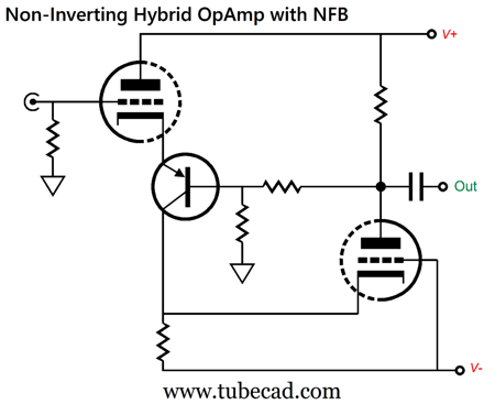
The top triode forms a bastode (inverted cascode) amplifier with the PNP transistor. The signal developed at the collector resistor is in phase with the input signal. The bottom triode is configured as grounded-grid amplifier, which means no phase inversion. The result is no phase inversion at the output. The two-resistor negative feedback loop drives the transistor's base. Making an actually useable hybrid OpAmp that delivers unity-gain with a good PSRR requires some work.
Each triode and the transistor draw 5mA of current and each dissipates about 0.5W of heat. The two zeners are there to limit maximum output voltage swing of the hybrid OpAmp and to limit the maximum cathode-to-plate voltage on the bottom 6DJ8 triode at startup. The grounded-grid amplifier gets an Aikido-mojo PSRR enhancement through the two-resistor voltage divider that bridges the two power-supply rails, which leaks enough of the positive rail's ripple to the grid to force a power-supply noise null at the output. If we replace the bottom triode's grounded-grid amplifier topology with a grounded-cathode amplifier topology, the hybrid OpAmp will invert the input signal at its output. Post 206 shows several possible arrangements, such as the following.
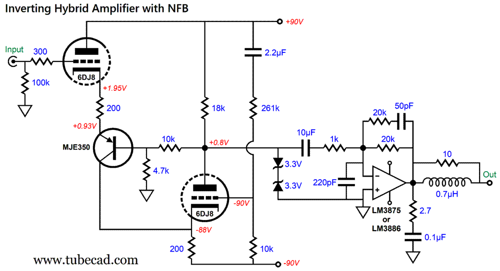
Let's take this topology and add a chip power amplifier.
Note that the 10µF coupling capacitor has been replaced by a capacitor one hundred times smaller in value; yet, the low-frequency cutoff frequency is about 8Hz. How is that possible? Note where the 49.9k negative-feedback-loop resistor terminates—i.e. on the other side of the coupling capacitor. In other words, the 0.1µF capacitor is enclosed within the negative feedback loop, so its value is effectively magnified. This is a huge, huge advantage if you buying high-end copper-foil capacitors from Europe. Pretty much all is good with this design except its PSRR. The problem with its PSRR is that it exhibits none. In other words, there is no rejection; in fact, there is slight amplification. Time to add some Aikido mojo.
The 715K resistor samples just enough of the negative power-supply rail ripple to force a null at the output.
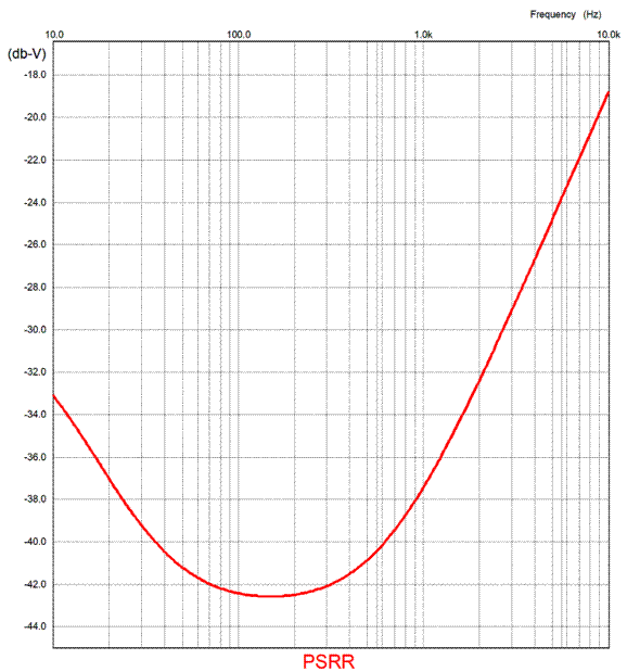
The PSRR has been improved by -40dB at 100Hz. My fear was that the hybrid OpAmp frontend would not exhibit enough of the desired single-ended cascade of harmonics. I needn't have worried. Here is the SPICE-generated Fourier graph for 1Vpk of output at 1kHz from the frontend.
I like how the 3rd harmonic is suppressed more than is the 4th harmonic.
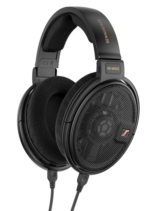
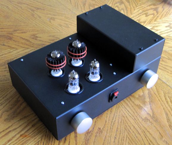
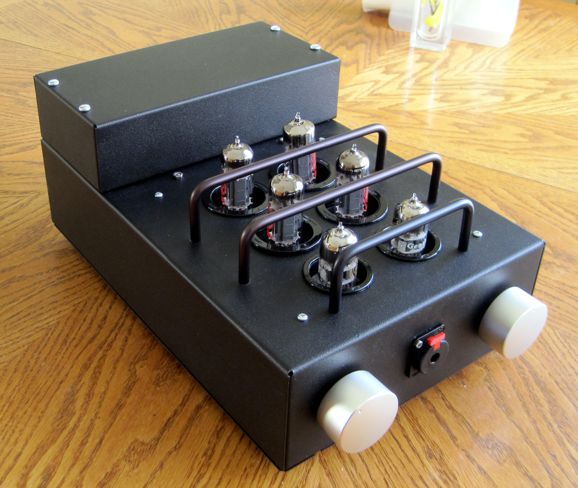
Sennheiser HD 660S2 Headphones Why bother mentioning any of this? The Sennheiser HD 660S2 headphones are 300-ohm types, which makes them ten times more suitable for tube powering than 32-ohm headphones. Tubes work best at delivering big voltage swings with light current demands. In contrast, solid-state devices, like smart phones and personal music devices (aka MP3 players), are voltage limited, but not current limited, so low-impedance headphones work best with these devices, as usually only 1Vpk of output signal is available. In contrast, the 300-ohm Sennheiser headphones require up to 3Vpk to sing, but only 10mA of peak current swing, something that a 6DJ8 or 12BH7 or ECC99 can deliver. So, how do the HD 660S2 sound? After opening the box, I drove the headphones with a bass-heavy album at high volume for 24 hours, so as to let them break in further. Although I am not convinced that electronic gear needs to break-in over weeks (my guess is, rather, that our ears need weeks to adjust to the new gear), but I do know for certain that loudspeaker drivers need to break in, as I have measured the changes in Thiele-Small parameters. My big fear was that the HD 660S2's bass would prove too plump and blubbery for my taste, as most of its reviews commented on its greater bass production over the previous version, the HD 660S. I am not a Beats headphones fan. I do not revel and rejoice in bloated bass. Once again, how did the HD 660S2 headphones sound? They sounded different with every amplifier. What is being reviewed, the headphones or the amplifiers? This is the huge problem with all audio reviews, as we never know what the rest of the audio chain is contributing to the sound we hear. An audio reviewer lauds the smooth highs from a loudspeaker, but we do not know that his DAC delivers screechy highs, which the overly-dull sounding tweeters erase. I listen to the HD 660S2 headphones with seven different headphone amplifiers, three all-tube designs, one of which even sported a tube rectifier, and two hybrid amplifiers, along with two pure solid-state designs. I was particularly interested to hear how the headphones would fare with one of my all-tube designs, as it purposely presented a relatively high output impedance.
My Post 503 details the design and its construction. Here is a longish quote from that post:
One danger with quoting oneself is knowing when to stop, as the urge to go on is strong. Nonetheless, I must add this one additional quote from this post:
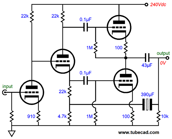
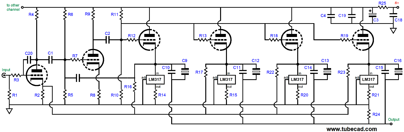
Verily, verily. The headphone amplifier's simplified schematic shows how the output stage effectively consists of two grounded-cathode amplifiers in push-pull arrangement.
The 390µF capacitor that bridges the output to the split-load phase splitter's bottom resistor ensures equal amplitude drive signals to the two output triodes. Neither output triode functions as a cathode follower; both work as grounded-cathode amplifiers. If the output triodes had been configured as push-pull cathode followers, the output impedance would be about 100 ohms with ECC99 tubes; configured as grounded-cathode amplifiers, 2300 ohms. The midrange poured forth angelically. Acapella voices and female singers lived in my ears. Natural. Effortless. This what tube sound is all about. Well, as expected, this headphone amplifier produced the most bass of all the amplifiers. The bass wasn't egregiously excessive by any means; indeed, I bet it is what 90% of listeners would delight in it, happy to hear the Beatification of Sennheiser sound. The bass was a tad too exuberant for me, however, so gave the Tilt-Control one turn to the right, thereby restoring frequency balance. (Many recording come pre-bass-boosted, however, so two twists are needed.)
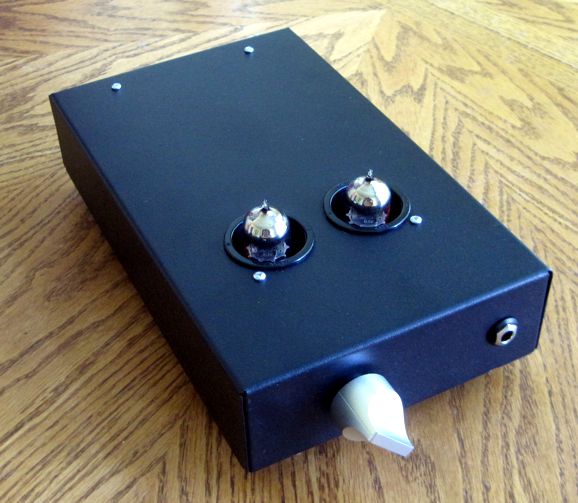
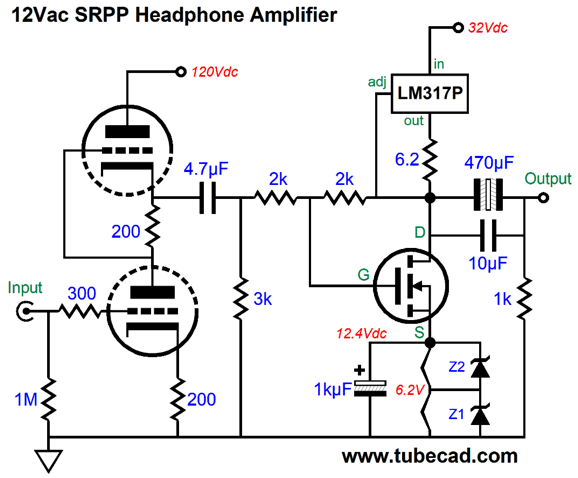
My ears truly liked the sound from the single-ended all-tube headphone amplifier with a low output impedance and from the 12Vac SRPP Hybrid headphone amplifier. The single-ended amplifier is interesting, as it uses four constant-current source loaded cathode followers per channel.
See Post 489 for more details on this design.
The SRPP design holds two power-supply rails:
Both are single-ended efforts. I am fairly sure that the all-tube design would beat the SRPP design handily, if it didn't contain a fan that can be heard with open-back headphones like the HD 660S2. Sadly, the fan is needed as the four output tubes produce a lot of heat. My favorite all-solid-state headphone amplifier was also a single-ended design. In addition, its negative feedback loop does not extend to the output stage.
See Post 454 for more information on this design. I also listened to the HD 660S2 with several electronic devices that sported headphone jacks, such as my smart phone, tablet, a Sony personal music player, and one of my DACs. I was surprised that I never bemoaned the lack of power. (I do tend to listen at lower volume levels than most audiophiles, in spite of what my wife might tell you.) Apparently Sennheiser is using stronger magnets. If this review strikes you as a tad illaudatory, I must stress that the HD 660S2's are truly fine headphones. They sound fresher, more agile, and sprightly than my old HD650 headphones. My issue of discontent was and remains that I long for new electrostatic headphones. The HD 660S2 do approach the electrostatic flavor, mostly due to their being backless and low-mass, but they remain recognizably dynamic headphones. If Sennheiser contacted me and asked for my input, I would tell them that their headphones are too tight on my head—and always have been. I admit that I have a fat head (in fact, my eyeglass frames are made by Fatheadz Eyewear), but surely I am not alone. Some means of width adjustment is an obvious improvement. What is not obvious is that one of the main reasons that electrostatic sound amazing is that the electrostatic diaphragm weighs a tiny fraction of the dynamic headphone's diaphragm (and voicecoil assembly and spider and surround); or in the case of planar electromagnetic headphones, a fraction of the plastic film and etched copper traces. Physics tells us that we can achieve the same frequency bandwidth and SPL by just delivering more power to the movement of the heavier diaphragm. True enough. The hidden problem is that the headphones are not locked in a steel vice, but simply rest on our heads, with soft cushioning around our ears, which are nothing like a heavy and stiff vice grip. As the heavier diaphragm moves, Newton's third law kicks in, smearing the sound, as for every action there is an equal and opposite reaction. The cone pushes towards your ear, but the frame moves slightly away from your ear, subtracting from the cone's motion in slurred fashion. The lighter the diaphragm or the heavier the headphone's frame, the less the reaction, thus less smearing. Have you noted how massive super high-end $$$ headphones are? I have. (In fact, I am thinking about creating a lead rings to attach the backs of the HD 660S2 frames.) A super clever workaround—one that would allow for the continued use of the existing light headphone frames and plush ear-pads, but would overcome Newton's law is to borrow the designs concept from recoilless sniper rifles (wherein two bullets are fired at once, one shooting forward towards the target, one shooting backwards into a clay mound within a rear chamber; or those recoilless designs that allow a controlled amount of hot gas to escape to the rear). No recoil, as the two actions cancel.
Well, we could add a secondary dynamic driver behind the existing driver, with both operating in phase, so the diaphragm motions cancel. Wouldn't that make backless headphones even more annoying to others within earshot, as more sound would escape? Possibly more mids and highs, but the bass frequencies would be diminished as the backs of the drivers emit sound out of phase with the sound at their front. (The ear would still hear these low frequencies, as the ear-cup seals off the ear from the cancellation.) By the way, the rear driver does not need to produce high frequencies, just bass frequencies. In fact, high intrinsic voicecoil inductance becomes a feature, as it would naturally impose low-pass filtering. But who said anything about rear sound production? The rear-firing driver only needs to move the same amount of mass, not to produce the same SPL. For example, it could hold only a relatively heavy voicecoil assembly (something like a ring-emitter tweeter) or a longish ring (i.e. tubular roll) of metal or heavy plastic attaching to the voicecoil, but no diaphragm. In fact, if we were particularly clever, we would use the existing magnet structure for both the front and rear voicecoils:
Since the rear voicecoil is so large, its mass can easily match that of the entire front voicecoil and cone. Indeed, we can use resistive surrounds to match the air resistance that the front diaphragm encounters. One down side is that the rear voicecoil must be powered along with the front driver's voicecoil. If both voicecoils present the same impedance, then the entire headphone impedance halves, assuming both are in parallel. Well, a 150-ohm headphone is still a relatively tube-friendly load. By the way, there is no reason why this driver construction could not be also applied to loudspeaker woofers. In fact, the rear voicecoil could be driven by an internal class-D power amplifier, whose input signal would be massaged (i.e. filtered and equalized) to deliver the optimal output. (Imagine if I worked as a patent attorney.) Sennheiser, get to work, and then run to the patent office. (As a thankyou of sorts, I would gladly welcome a pair of HD 660S2² headphones. I love the squared symbol; imagine if I worked in a marketing department.)
Music Recommendation: Little North's While You Wait Amazon Music and Qobuz offer the album in 24-bit, 96kHz resolution. Give the title track, "While You Wait," a listen and you will probably be as hooked as I am.
//JRB
Did you enjoy my post? Do you want to see me make it to post 1,000? If so, think about supporting me at Patreon.
User Guides for GlassWare Software
For those of you who still have old computers running Windows XP (32-bit) or any other Windows 32-bit OS, I have setup the download availability of my old old standards: Tube CAD, SE Amp CAD, and Audio Gadgets. The downloads are at the GlassWare-Yahoo store and the price is only $9.95 for each program. http://glass-ware.stores.yahoo.net/adsoffromgla.html So many have asked that I had to do it. WARNING: THESE THREE PROGRAMS WILL NOT RUN UNDER VISTA 64-Bit or WINDOWS 7, 8, and 10 if the OS is not 32-bit or if it is a 64-bit OS. I do plan on remaking all of these programs into 64-bit versions, but it will be a huge ordeal, as programming requires vast chunks of noise-free time, something very rare with children running about. Ideally, I would love to come out with versions that run on iPads and Android-OS tablets.
|
I know that some readers wish to avoid Patreon, so here is a PayPal button instead. Thanks.
John Broskie
John Gives
Special Thanks to the Special 94 To all my patrons, all 94 of them, thank you all again. I want to especially thank
I am truly stunned and appreciative of their support. In addition I want to thank the following patrons:
All of your support makes a big difference. I would love to arrive at the point where creating my posts was my top priority of the day, not something that I have to steal time from other obligations to do. The more support I get, the higher up these posts move up in deserving attention.
If you have been reading my posts, you know that my lifetime goal is reaching post number one thousand. I have 401 more to go. My second goal was to gather 1,000 patrons. Well, that no longer seems possible to me, so I will shoot for a mighty 100 instead. Thus, I have just 16 patrons to go. Help me get there. Thanks.
Only $12.95 TCJ My-Stock DB
Version 2 Improvements *User definable Download for www.glass-ware.com
|
|||


| www.tubecad.com Copyright © 1999-2024 GlassWare All Rights Reserved |