15 March 2024 Post Number 598
In my last post, we saw Strickland's Trans Nova solid-state power amplifier design. This time we will look into his hybrid push-pull power amplifier for directly driving electrostatic loudspeaker panels. Strickland's patent points out that electrostatic loudspeakers present a bad load for most conventional power amplifiers, as the electrostatic panels are effectively big capacitors, capacitors which require high-voltage swings to develop adequate SPL, which in turn requires the use of an audio step-up transformer—all of which are far from the ideal of a simple purely resistive 8-ohm load. His high-voltage push-pull amplifier sidesteps the need for the transformer.
Much like Harold N. Beveridge's earlier electrostatic-amplifier design (US 3,773,976), Strickland uses four high-voltage pentodes in an SRPP arrangement. Unlike Beveridge's more elaborate design that drives both the stators and the diaphragm, Strickland's amplifier only drives the stators, leaving the diaphragm to be passively polarized through a high-ohmage resistor (20M or higher), as is the common practice in electrostatic loudspeakers. In other words, Strickland's effort is similar but subtractive of Beveridge's prior work. For example, not only did Beveridge's amplifier drive the diaphragm along with the stators, it also employed a clever and active means to center the diaphragm between the stators. Still, there's enough meat in Strickland's amplifier to warrant a close examination. The amplifier actually contains sub amplifiers.
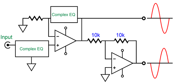
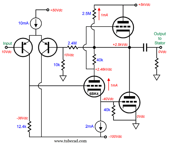
The unbalanced input signal passes through passive and active equalization before it is split into balanced output signals. Up to this point, OpAmps are used; thereafter, discrete devices, which is when things get interesting. (In the following schematic, I didn't know the actual values used, so I guessed. Furthermore, Strickland's patent doesn't detail the pentode or transistor types. I assume a 6KD6 or 36KD6 pentode was used, the latter being used in the Beveridge electrostatic amplifier.)
Our old friend the bastode differential amplifier makes an appearance here, with it being in control of the SRPP output stage that holds two pentodes.
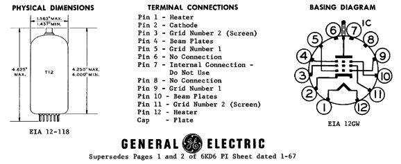
The 6KD6, a 33W beam-power pentode in the 12-pin Duodecar base (i.e. compactron) designed for use in horizontal-deflection amplifier circuits in color TVs, can withstand 7kV peak plate voltages and pass up to 1.4A peak amperes of current and an average current flow of 400mA. Mind you, it cannot do both at once; in other words, it cannot survive 7kV peak voltage swings with 1.4A of current delivery. With a cathode-to-plate voltage of 2,500V and with an idle current draw of 10mA, the plate would dissipate 25W!
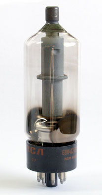
6BK4 photo by John Atwood
When dealing with extreme high-voltages, not much current is needed to deliver a wallop. For example, the 6BK4 beam-triode tube sports a plate dissipation of 25W and a maximum cathode current flow of 1.5mA. Yes, 1.5 milliamperes. The paradox is resolved when we learn that the triode can withstand up to 55kV of plate voltage. (By the way, this triode offers an amplification factor, mu, of 2,000.)
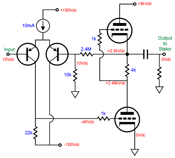
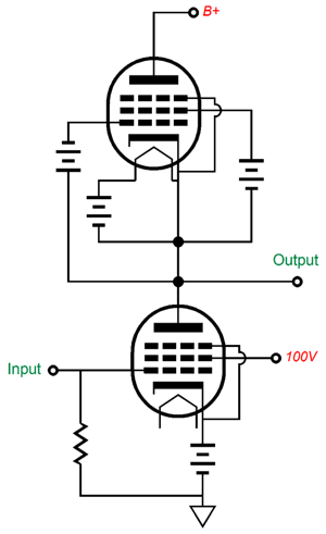
In the circuit shown above, the top and bottom pentodes cannot share the same heater power supply, as the top pentode's cathode must be referenced to its cathode, which will swing thousands of volts. Thus, it must get its own floating heater winding or DC power supply. The zener and the diode are there as protection circuitry. To better see how this high-voltage amplifier works, let's substitute the pentodes with triodes.
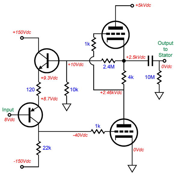
This simplified version is operationally identical with the original. The PNP transistor's base is the non-inverting input, while the NPN transistor's base is the inverting input, to which the negative feedback loop delivers 1/250th of the output signal, which implies a gain of 1:250, which further implies the bastode input stage must see an input voltage swing of around ±8Vpk to achieve full output. I know that some readers cannot see how the bastode works as a differential amplifier, so let's swap it out for the more conventional differential amplifier arrangement.
The 10mA constant-current source could be run off an much lower B+ voltage, say +50Vdc, or even +30Vdc. The SRPP output stage runs an idle current of only 10mA as well, which implies a 25W plate dissipation from each triode, making for a total of 100W for one channel, as each channel requires two of these high-voltage amplifiers. If you are thinking class-A, you are on the right track. In fact, as the SRPP, like the White cathode follower and SRCFPP, belongs to the triad of lazy push-pull output stages, it must be operated in strict class-A. (Since the bottom tube controls the top tube's current conduction, if the bottom tube ceases to conduct, it loses all control over the top tube.)
If a more elaborate totem-pole arrangement were used, wherein both the top and bottom output tube can be driven beyond the class-A window of current conduction, we could get much bigger output current swings.
Gone are the SRPP aspects, leaving only an output stage capable of running in class-AB. How can this be a feature? Simple: in order to charge and discharge capacitance quickly requires current, as slew-rate times capacitance equals the requisite current:
I = Slewrate x C
Slew rate (SR) is the measure of how quickly a signal can increase or transition in voltage, which is usually measured in micro-seconds (µs). If an amplifier can swing from 0V to 10V in one µs, then it can slew at 10V/µs; if in one nano-second (ns) it can swing 1Vpk, then it can slew at 1000V/µs, as a nano second is one thousand times shorter in time than a µs. Slew rate in volts per micro-seconds can be found from this formula:
Slewrate = 2 · pi · Freq · Vpk / 1,000,000
where pi equals 3.14159 and Freq equals the highest frequency you wish to reproduce and Vpk is the highest peak voltage swing. Electrostatic loudspeakers are basically big capacitors. The higher the frequency and the bigger the voltage swing, the greater will be the current demand. This is something often forgotten, as the huge high-voltage swings seem the only necessary feature. In other words, both big voltage swings and current delivery are required.
If we solve for slewrate, we get the following:
Slewrate = Current / Capacitance
We also get:
Capacitance = Current / Slewrate
Current = Slewrate / Capacitance
With an SRPP output stage that idles at 10mA, the peak output current flow is 20mA. With an electrostatic panel that presents 1,000pF (i.e. 1nF) of capacitance, the maximum slew rate will be 10V/µs, which further implies a peak voltage swing of 79.6Vpk at 20kHz, but a peak swing of 1592V at 1kHz.
Vpk = (1,000,000 ·SR) / (2 · pi · Freq)
Fortunately, most music is bass heavy and high-frequencies light. In other words, we seldom need full power bandwidth from 20Hz to 20kHz. Nonetheless, more reserve potential voltage swing at high frequencies is always welcome. In Strickland's patent we read the following:
"Electrostatic transducers capable of covering the audio spectrum from 30 Hz to 20,000 Hz present a capacitive load characteristic which is very difficult to drive. Such transducers typically require a push-pull signal approximating 3000 volts r. m.s. at low frequencies and about 1000 volts r.m.s. at mid-band and high frequencies. Such transducers have a highly capacitive character typically approximating 800 picofarads. This causes the driving source to see an impedance varying from about 7 megohms to less than 10 kilohms."
By the way, I recommend reading the patent, as most of it must have been written by Strickland himself—in sharp contrast with most patents that are mostly written by patent attorneys. For example, Strickland points out the problem of the house-ground connection introducing hum and offers a two-diode remedy. One caveat worth mentioning is that a patent's text is meant to achieve the legal goal of being granted an exclusive patent, not to explicate and make comprehensible the invention. For example, Strickland sites Otto Schmitt's long-expired 1934 patent to avoid highlighting his having copied Beveridge's SRPP output stage:
"…employing the Schmitt connection (U.S. Pat. No. 1,950,365, Mar. 6, 1934) operating in push-pull."
The sleight of hand here is that the Schmitt arrangement consists of a pentode operating in single-ended with active load that approximates a constant-current source, not at all a push-pull topology. In fact, the Schmitt arrangement makes use of batteries as floating power supplies, thereby vastly increasing the active load's output impedance. (If you read Schmitt's patent, you realize that his goal was supremely high gain, never push-pull operation.)
Schmitt's circuit creates a near constant-current source out of the top pentode, but not a push-pull output stage. Strickland could have sited C. A. Wilkins' 1965 patent, US 3,184,687, as shows an SRPP output stage based on triodes—perhaps, it hadn't expired yet.
With the non-SRPP output stage that uses a split-load phase splitter shown previously, we could set the idle current to only 5mA (12.5W of plate dissipation) and expect to get peak output current swings of 100mA, i.e. five times greater than the SRPP, which implies five times larger peak voltage swings at 20kHz. In contrast, the Beveridge electrostatic power amplifier also runs an SRPP output stage, one with a lower B+ voltage, but as it drives both the diaphragm and the stators, it effectively can swing twice as big output voltages, much in the same way that a bridge power amplifier topology can swing bigger output voltage swings with the same bipolar power-supply rail voltages as the conventional solid-state power amplifier. The following is the tube-based overview from Beveridge's electrostatic power amplifier patent.
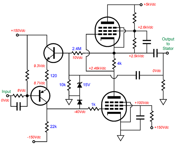
Interestingly enough, the zener diodes are shown upside-down, but are shown correctly later in the patent where transistors drive the output tubes. In this schematic, the stators are fixed, with the top one getting the full B+ voltage, while the bottom one is grounded via the inductor. The diaphragm is driven directly by the tube-based output stage and at idle sees one-half of the B+ voltage. Seemingly, no negative feedback loop is employed, but it's there nonetheless. The way it works is that the triode at the extreme left is the input tube, and it functions as a grounded-cathode amplifier, i.e. a voltage-to-voltage converter, whose output cascades into a pentode configured as a voltage-to-current converter, whose output cascades into the bottom output pentode, making the output stage function as a current-to-voltage converter. Translating this circuit into an all-solid-state affair, might look like the following:
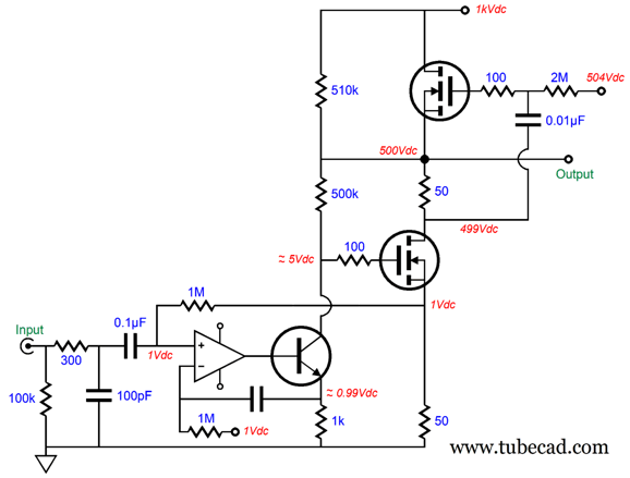
I purposely lowered the B+ voltage to only 1kV, as higher voltages tend to make the mind go wobbly. I have yet to run this topology in SPICE, so the top high-voltage MOSFET might be missing a needed source resistor. (In fact, I am sure it is.) The idea here is that the OpAmp sets the output MOSFET's idle current to 1V/50-ohms or 20mA; it also establishes a voltage-to-current conversion of 1V-to-1mA with the NPN transistor and its 1k emitter resistor. The 500k resistor is the I-to-V converter resistor and constitutes the output stage's negative feedback loop. The MOSFETs run hot (about 10W each) in spite of the low 20mA idle current, so they must attach to a heatsink. Since this SRPP output stage must be run in strict class-A operation, the peak output current delivered will be twice the idle current, or 40mA peak.
If this high-voltage amplifier works out, it could be doubled and used to drive electrostatic headphones or an electrostatic tweeter panel. If we increase the B+ voltage and use truly high-voltage MOSFETs, it could drive electrostatic loudspeaker panels. Still, my preference would be to use a MOSFET-based split-load phase splitter to drive the output MOSFETs, thereby sidestepping the SRPP limitations.
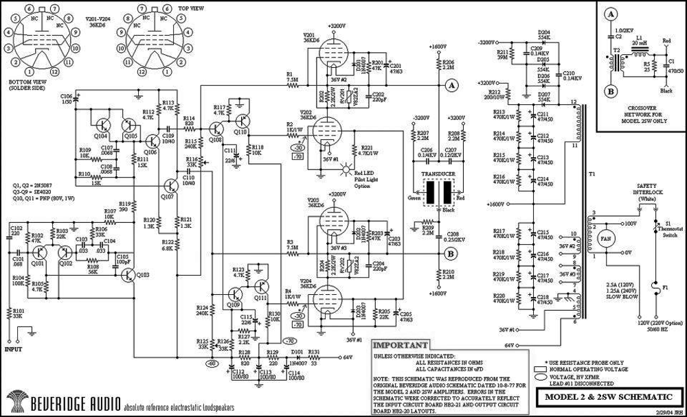
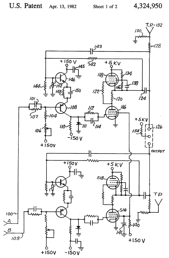
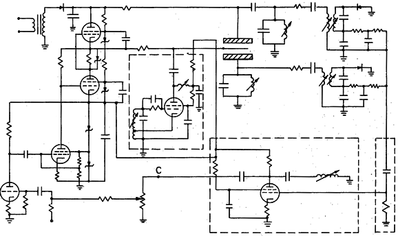
If we examine the following schematic of an actual Beveridge hybrid electrostatic power amplifier, we can see how both the stators are driven and the diaphragm is driven at the same time with the balanced outputs. (Apparently, Beveridge abandoned the diaphragm-centering circuitry in later production.)
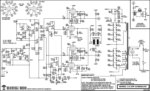
Click on schematic to see enlargement
Note the clever way the pentode screen voltages are developed from the 36Vac heater windings. (A voltage-doubling rectifier circuit could have been implemented.) No doubt, many will be confused by the transistor portion of the circuit. It's not as bad as it looks. Basically, three amplifiers and one phase splitter are used to drive the two pentode-based SRPP output stages. (Transistors Q104 & Q105 function as protection diodes.) The stators and the diaphragm are capacitor coupled to the balanced outputs. Note how one stator is biased to +3.2kV, while its partner is biased to -3.2kV; the diaphragm is at ground potential. Yes, ground potential, so the bias voltage is delivered to the stators, not the diaphragm.
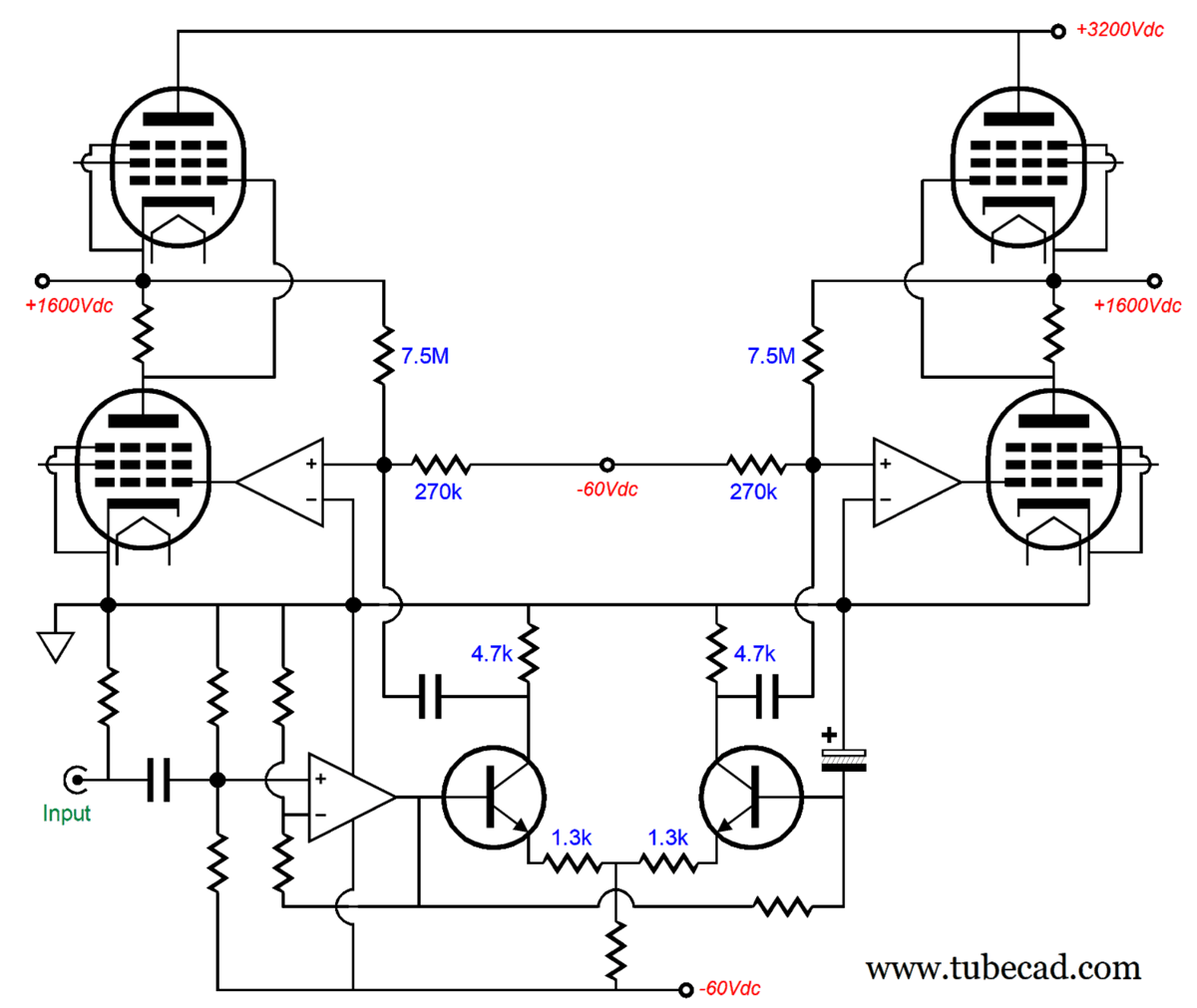
Here is the conceptual re-drawing of the Beveridge design.
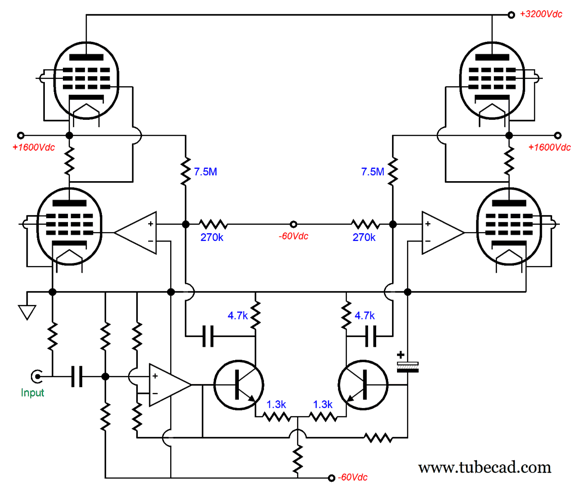
Click on schematic to see enlargement
The two amplifiers that direct drive the bottom pentodes are effectively configured as inverting amplifiers, as the pentodes invert the phase at their plates. The 4.7k phase splitter collector resistors form the first half of the two-resistor negative feedback loop with the 7.5M resistors, implying an AC gain of 7.5M/ 4.7k or 1:1596. The two 270k resistors force the 1.6kV DC offset at the outputs. (If the math seems off it is due to the amplifiers that directly drive the pentode grids do not actually ground their inverting inputs to ground but to a small negative voltage.)

Since I don't own electrostatic loudspeakers but do own Stax electrostatic headphones, I am always thinking about new electrostatic amplifiers to drive electrostatic headphones. (By the way, I absolutely hate working with ultra-high voltages, say anything above 400Vdc, so it's probably a good thing that I don't own electrostatic loudspeakers.) Over the last four decades, I have designed and built at least seven different electrostatic headphone amplifiers. All have held tubes as the output devices. I often point out that if you haven't heard electrostatic headphones driven by a tube-based headphone amplifier, you really haven't heard electrostatic headphones; instead, you have heard primarily bad solid-state amplifiers. By the way, I am sure that good-sounding solid-state electrostatic headphone amplifiers can be built, but that it will require extra effort.
Making a hybrid electrostatic headphone amplifier not only saves tubes, it offers the possibility of forgoing coupling capacitors, which are always a pain. The following design showcases the operational overview of a simple high-voltage amplifier.
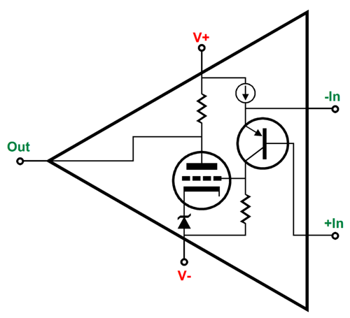
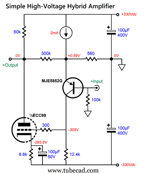
The high-voltage PNP transistor (MJE5852G) offers a collector-to-emitter breakdown voltage of -400V, along with an 80W maximum dissipation. (The NEC 2SA1871 PNP sports a -600V breakdown voltage, but might no longer be available in the TO-220 insulated package, leaving surface-mount as the only option.) The PNP transistor's base receives the input signal and drives the ECC99 triode to full output of ±250V peak. The 300k and 560-ohm resistors define the negative feedback loop and set a theoretical gain of 1:536, which is not achieved in practice due to the low gain from the triode. To make a usable electrostatic amplifier, we need to double up on the circuit.
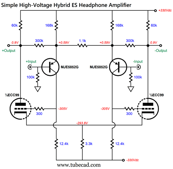
Note how we have lost the cathode-resistor bypass capacitor. Also note that we are using a shared cathode resistor. Of course, we could get fancier.
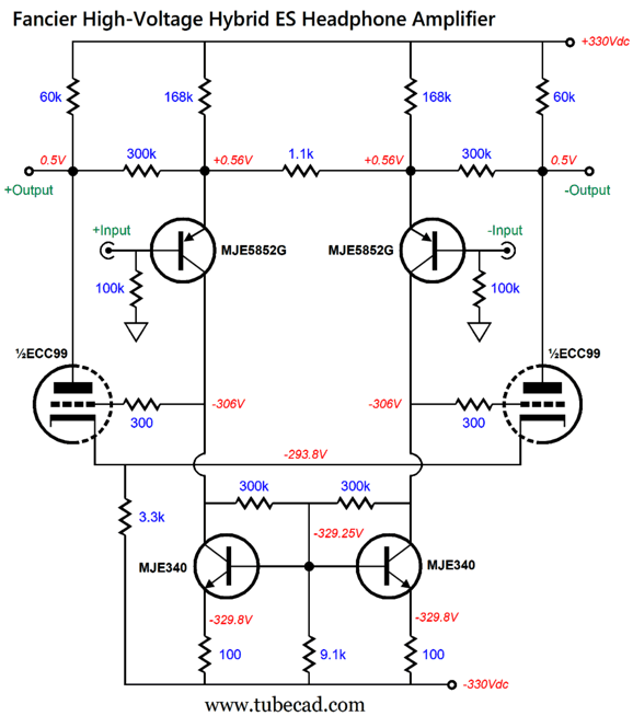
The simple collector resistors have been replaced by the fancier dual constant-current source with improved balance. Having gone this far, we might as well go ahead with fancier still.
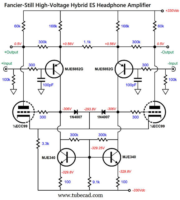
Note the protection diodes, which limit the maximum grid-to-cathode to no more than +0.7V. Also note the input RC filters that limits the high-frequency input signal's bandwidth. By the way, although I drew 60k plate resistors, 168k emitter resistors, 300k feedback resistors, I would actually use six 10k resistors in series to replace the 60k resistors; and, three 56k resistors in series to replace the 168k resistors; along with three 100k resistors for the 300k feedback resistors. Why? Voltage-induced distortion and greater wattage dissipation.
At the risk of losing many readers, here is the fanciest variation:
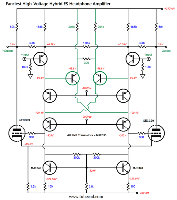
Click on schematic to see enlargement
Marked in peacock green, we see a distortion-reduction circuit made up of three resistors and two PNP transistors. Find the right value for the center resistor (300 ohms in this circuit) requires experimentation and patience, which probably explains why the circuit is neither popular nor well-known. In SPICE simulations, it's not too hard to get a -20dB reduction in all harmonics. By the way, this distortion-reduction circuit can be used in low-voltage balanced amplifiers.
Since we can buy a SiC N-channel MOSFET with a 900V maximum voltage rating, the C3M0280090D, we can replace the ECC99 triodes with MOSFETs—low input-capacitance SiC MOSFETs that is. The big issue other than high-voltage rating is low input capacitance. The problem is most power silicon MOSFETs present a high gate-to-drain capacitance; the exception is low-wattage high-voltage MOSFETs, such as the 33W IXTP02N120P or the 45W STP3LN80K5, both of which exhibit an input capacitance of a little over 100pF.
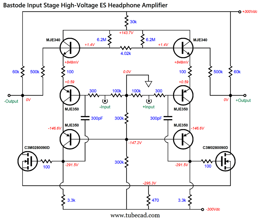
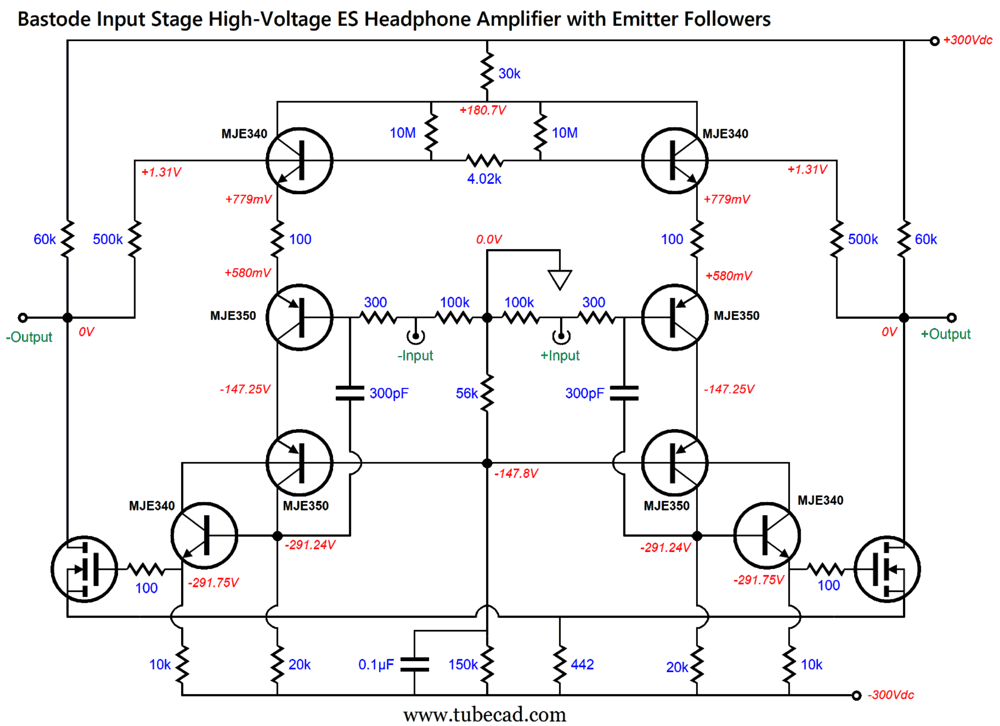
While we are at it, we can sneak in two bastode differential input stages.
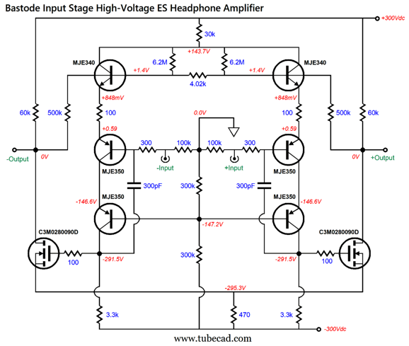
Click on schematic to see enlargement
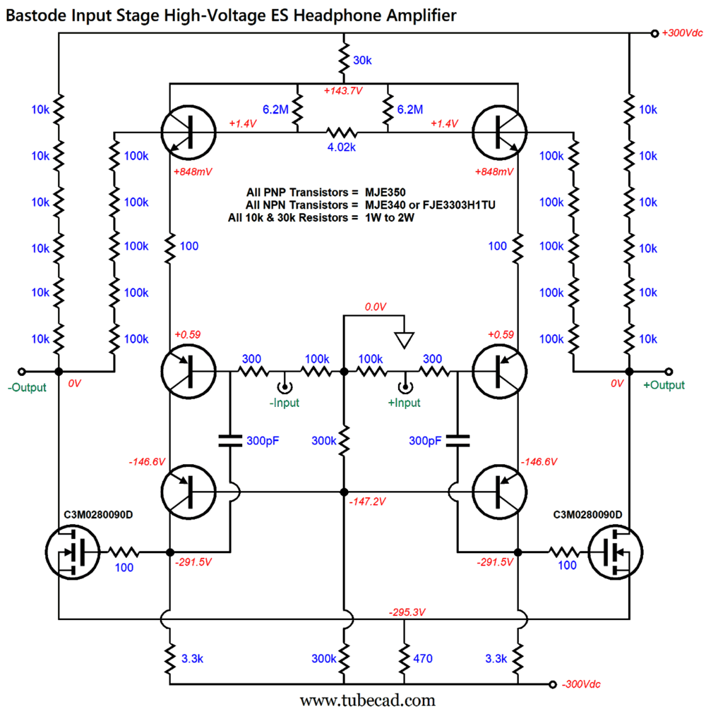
Note the lower bipolar power-supply rail voltages, which are due to the MOSFETs not needing the high overhead triode voltages. Also note the PNP transistors in cascode arrangement and the 6.2M resistors that undo the DC offset that would otherwise exist. In addition, the 300pF capacitors now terminate into the collector resistors, not ground, which provides better high-frequency stability. The total negative feedback resistance has gone up from 300k to 500k (five 100k resistors in series), and balanced gain equals ±1Vpk to 500Vpk-to-pk of output. Here is what the actual circuit would look like with all the series resistors.
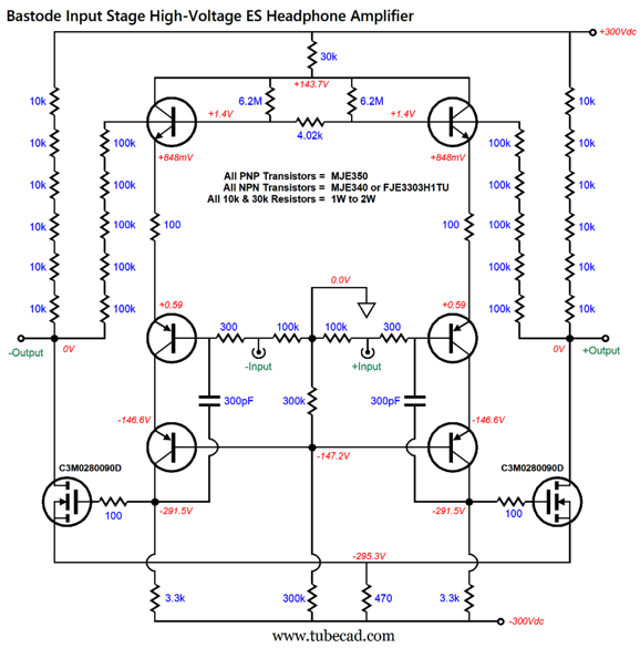
Click on schematic to see enlargement
The SiC (silicon-carbide) MOSFETs present such a low input capacitance that we can get away with the simple 3.3k collector resistors. On the other hand, if conventional high-voltage silicon MOSFETs were used, then I would add emitter-follower circuits to drive the gates.
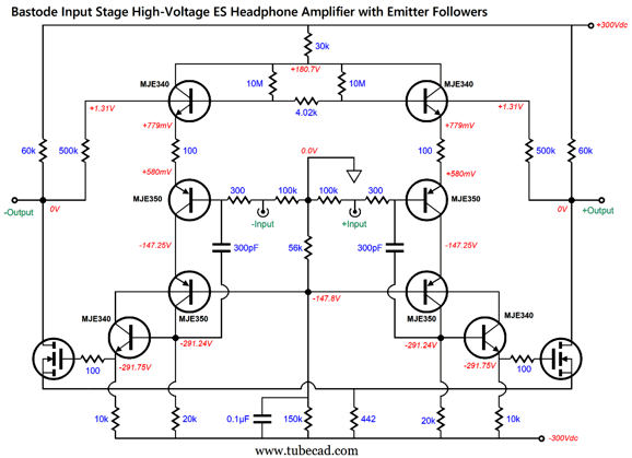
Click on schematic to see enlargement
Note that the 3.3k collector resistors have been replaced by 20k resistors. Also note the 10M DC offset correcting resistors. Speaking of DC offsets, one problem with SPICE simulations is that the power supplies are assumed to be perfect; reality isn't. For example, the wall voltage can vary from city to city, from block to block, from the first floor to the fifth floor in an old apartment building, and from hour to hour. Thus, a DC-offset-free circuit in SPICE can easily produce a substantial DC offset in reality. A good test to run in SPICE simulations is to vary the power-supply voltage by 90% to 110% and see what the idle current and DC offsets look like. For example, with the ±300Vdc bipolar power supply, the ±10% voltage drift equals ±270V to ±330V. Here is the SPICE-generated graph for the circuit shown above.
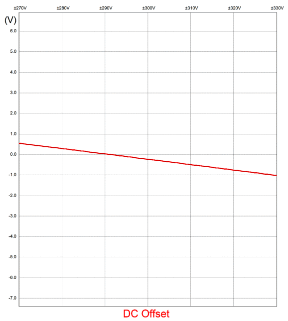
Not bad at all, as less than 1 volt of DC offset occurs. By the way, DC offsets are only a problem if they occur between the two stators and if they are large; do not forget that the diaphragm gets a +580Vdc bias voltage. By the way, if we replaced the shared 442-ohm source resistor with a constant-current source, the DC offset would have been ±30V with the 10% reduction in wall voltage and a 10% increase in wall voltage, assuming no power-supply regulation. In other words, let's keep the source resistor.
The SPICE-generated Fourier graph of harmonics at 100Vpk of differential output into a 110pF load at 1kHz shows very low distortion.
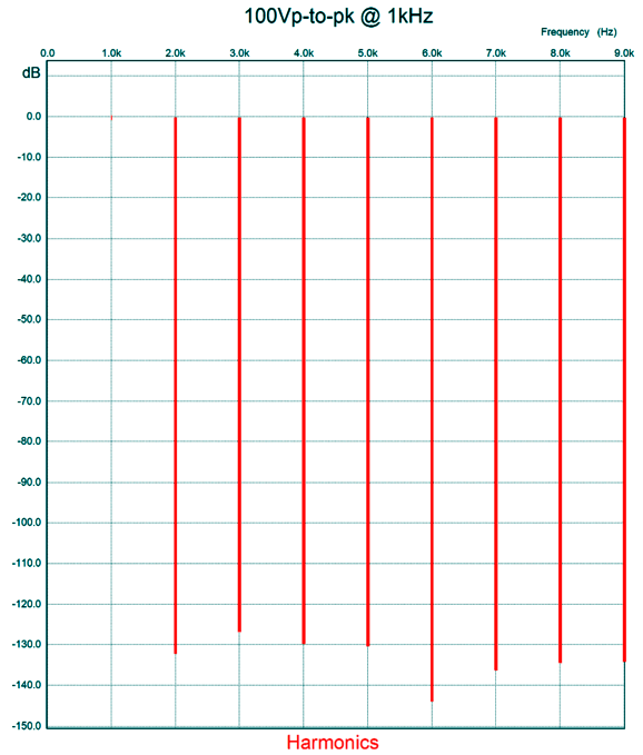
To be -40dB down is to have 1%; -60dB, 0.01%; and -100dB, 0.00001%. Even if reality is 100 times worse (i.e. 40dB), the results would still be amazingly fine. So fine, in fact, that I don't see the need for adding any further distortion-reduction circuits. On the other hand, I can see a need to replace the two 60k load resistors (i.e. the six 10k resistors in series) with active loads. Why? Increased output voltage swings and greater high-frequency bandwidth. Resistor-loaded class-A amplifiers are only 8.33% efficient, whereas constant-current-source loaded amplifiers are 25% efficient, and inductive-loaded are 50%. (These are the theoretical maximum efficiencies; real class-A only get close to these percentages.) What would an active load look like? How about a 900V depletion-mode MOSFET with a source resistor to set its idle current?
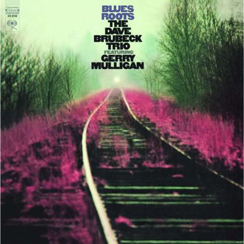
Of course, I was going to love this album, as this is the music of my youth. Brubeck LPs played along with The Beatles and Mulligan LPs were in the same mix with The Moody Blues. This particular album, however, is entirely new to me, in spite of my affection for both Brubeck and Mulligan. One standout difference is that Dave Brubeck's usual saxophonist was Paul Desmond, who played an alto sax, while Mulligan blows a baritone sax, which makes this album at once both very familiar, yet strange to my ears. Ostensibly an homage to The Blues, this album's first track, "Limehouse Blues," isn't a blues composition. In other words, if you came in expectation of Delta or Chicago Blues, you will be disappointed. Let's call it blues inspired or influenced. On the other hand, if you came in the expectation of hearing great jazz, you will not be disappointed.
Amazon Music and Qobuz both offer it in glorious 96kHz 24bit. (I ended up dropping Tidal again, as it just didn't offer anything beyond what I was already getting from Amazon and Qobuz, besides it cost more than these two alternatives. Once Tidal has purged their catalog of MQA recordings, replacing them with straight FLAC recordings, I might come back.)
//JRB
Did you enjoy my post? Do you want to see me make it to post 1,000? If so, think about supporting me at Patreon.

Just click on any of the above images to download a PDF of the user guides.
For those of you who still have old computers running Windows XP (32-bit) or any other Windows 32-bit OS, I have setup the download availability of my old old standards: Tube CAD, SE Amp CAD, and Audio Gadgets. The downloads are at the GlassWare-Yahoo store and the price is only $9.95 for each program.
http://glass-ware.stores.yahoo.net/adsoffromgla.html
So many have asked that I had to do it.
WARNING: THESE THREE PROGRAMS WILL NOT RUN UNDER VISTA 64-Bit or WINDOWS 7, 8, and 10 if the OS is not 32-bit or if it is a 64-bit OS.
I do plan on remaking all of these programs into 64-bit versions, but it will be a huge ordeal, as programming requires vast chunks of noise-free time, something very rare with children running about. Ideally, I would love to come out with versions that run on iPads and Android-OS tablets.
|
|
|
|
I know that some readers wish to avoid Patreon, so here is a PayPal button instead. Thanks.
John Broskie
John Gives
To all my patrons, all 96 of them, thank you all again. I want to especially thank
Concordio Anacleto
Walter Clay
King Heiple
Kuldeep
Amy D. McNeil
Paul Radovan
Christian Rintelen
Jason Stoddard
Kelvin Tyler
Dwight Warren
I am truly stunned and appreciative of their support. In addition I want to thank the following patrons:
John Atwood
Hal Clark
Dean Bailey
Jim Burnes
Eduardo Fayad
Scott Fraser
Manny Gagliano
Mike Galusha
Richard Hansen
Andreas Hierzenberger
Erik Hoel
Dean Kayser
Tom Kelly
Thomas Kifowit
Francis King
Frank Klapperich
Neil Kovacs
Przemek Lach
Robert
Ron Lee
偉良 林 (David Lin)
Amy D. McNeil
Csaba Molnar
Joe Mooney
John R. Murray
Seiichiro Nakakura
Larry Owens
John Puma
Paul Reid
Marty Reiss
Paulo Mario dos Santos Dias de Moraes
Blake Swaney
Michael Taylor
Brian Terrell
James Tiemann
Dwight Warren
Andrew White
Sergey Yegourno
All of your support makes a big difference. I would love to arrive at the point where creating my posts was my top priority of the day, not something that I have to steal time from other obligations to do. The more support I get, the higher up these posts move up in deserving attention.
If you have been reading my posts, you know that my lifetime goal is reaching post number one thousand. I have 402 more to go.
My second goal was to gather 1,000 patrons. Well, that no longer seems possible to me, so I will shoot for a mighty 100 instead. Thus, I have just 4 patrons to go.
Help me get there. Thanks.
Only $9.95
to start designing
tube-based crossovers
and much more...
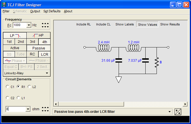
TCJ Filter Design
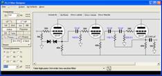
The Tube CAD Journal's first companion program, TCJ Filter Design lets you design a filter or crossover (passive, OpAmp or tube) without having to check out thick textbooks from the library and without having to breakout the scientific calculator. This program's goal is to provide a quick and easy display not only of the frequency response, but also of the resistor and capacitor values for a passive and active filters and crossovers.
TCJ Filter Design is easy to use, but not lightweight, holding over 60 different filter topologies and up to four filter alignments:
Bessel,
Butterworth,
Gaussian,
Linkwitz-Riley.
While the program's main concern is active filters, solid-state and tube, it also does passive filters. In fact, it can be used to calculate passive crossovers for use with speakers by entering 8 ohms as the terminating resistance. Click on the image below to see the full screen capture.
Tube crossovers are a major part of this program; both buffered and un-buffered tube based filters along with mono-polar and bipolar power supply topologies are covered. Available on a CD-ROM and a downloadable version (4 Megabytes).
|