| John Broskie's Guide to Tube Circuit Analysis & Design |
05 October 2006
Genius Grants Radically Different In giving my review of Morgan Jones’s new book, Building Valve Amplifiers, I have somehow given the impression to several readers that I sell his book(s) at my Yahoo! Store. I do not; in fact, I do not sell any books. Why not? The sad fact is that I am not even smart enough provide one of those paying links to Amazon.com, which provides a small kickback every time someone follows the link to Amazon's site and buys a book. Oh well. Speaking of not being intelligent enough, a good friend of my mine, Glenn, called the other day to offer solace for our not receiving a MacArthur Foundation (Genius) grant—once again.
This has been a running gag between Glenn and me for almost two decades, as we both have an immense, but unprofitable, yet important project within us. His is less practical than mine and is more noble because of it. Whereas Glenn seeks to reconcile and unify seemingly disparate and opposed theological/metaphysical systems, I just wish to map out as many of the unexplored territories of tube circuit topology as I can. Neither project is a money maker; both projects require a huge investment of time and effort. The age of gentlemen scholars is, alas, long dead. So, instead, we both trickle out our efforts, as a full frontal assault is simply impossible in our present situations. But what made being sidestepped this year by the folks at the MacAthur Foundation actually a tad bit poignant was that my wife actually knows one of this year’s grant recipients, which suddenly made having been chosen seem almost possible, although still not at all likely; remember, tube audio is only valued by 0.0000001% of the world’s population. (Besides, the iPod is deemed, by most, to deliver perfect sound, so why bother with tubes?) Still, I can dream, can’t I? If you are wondering what I would do with the grant money, the answer is easy: I would hire a fulltime nanny, build a soundproof workroom, buy an Audio Precision distortion analyzer, and hire some college kids to assemble about thirty of my circuit designs that I would otherwise never get to build. Once assembled, I would thoroughly test the circuits and publish the results here, as an open-source an endeavor as can be imagined. What a beautiful dream, particularly, the part about a soundproof workroom (indeed, you know it’s bad, when you find yourself envying those in solitary confinement). Well, enough sniveling. The following design concept is an example of one of those unprofitable, yet important projects. The premise is that I love tube-based voltage regulators, with just cause. Much in the same way as tube-based amplifiers sound better than their solid-state cousins do, so too do tube-based voltage regulators sound better than their solid-state equivalents. Most readers are not about to argue with me on this contention, so what’s new?
Tube-based voltage regulators
But even this high-voltage regulator has problems; for example, too little voltage differential across the top triode and too much across the bottom triode. In addition, such a regulator would be difficult to build for truly high voltages, say above 400V, as the triodes will require separate heater power supplies and few triodes can withstand a steady 1,200 volts, for example, which an 845-based single-ended amplifier would require. Moreover, such a regulator could not be used with low voltages or with solid-state equipment. Solid-state equipment? Why would anyone want to use a tube-based regulator with solid-state gear? Other than better sound, I cannot think of any good reasons. Why can’t we use a tube-based voltage regulator with solid-state circuitry, such as a solid-state power amplifier or DAC? Well, the easy answer is that solid-state circuitry loves low voltages and high current, whereas tube circuitry loves high voltages and low current. All true enough, but our task is not to swing 40-volt and 5-ampere peaks into 8-ohm loads, but simply to erase the one-volt of noise from a power supply rail. Before showing you how I would tackle the problem, imagine how you would do the same. Many are thinking that heavy-current triodes, like the 6AS7 and 6C33, are the answer. In other words, build effectively half an OTL amplifier configured as a voltage regulator. This solution begs the question: why not just build an OTL amplifier and be done with it? Others are thinking that some hybrid circuit is the only solution, letting the tube half provide the voltage swing and feedback control, while solid-state pass devices do the heavy lifting. This solution is as obvious as it is compromised, as the goal was to build a purely tube voltage regulator which could power solid-state circuitry. Ok, so how would I tackle this problem? I would use an electrical lever, in other words, a transformer. Imagine a single-ended amplifier whose output was in series with a low-voltage, high-current power supply rail (or a dangerously high voltage rail). Thus, instead of grounding one end of the output transformer’s secondary to ground, “ground” this end to the raw B+ terminal, leaving the other end of the secondary as the regulated output.
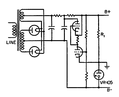
In the above schematic, we see what I have in mind. The output transformer’s winding ratio reveals the transformer’s current step ratio. For example, an output transformer with a 5k primary and an 8-ohm secondary holds an impedance ratio of 625:1 and a winding ratio of 25:1. Thus, an idle current of 100mA can be magnified into a 2.5A current swing. Amazing, yes; magic, no. The inverse of the winding ratio is the voltage step-down ratio. For example, if the triode’s plate can swing 100 volts in both directions, then the secondary’s output can only swing +/-4 volts, as 100V/25 = 4V. In theory, such a circuit, depending on the current drawn by the solid-state amplifier, could erase up to 4-volts of power supply noise. Of course reality will, no doubt, disappoint. "Wait a minute," many are thinking; "a transformer cannot pass DC currents, so the tube-based voltage regulator could never work to achieve DC voltage regulator." True, it cannot; but its aspirations are not that audacious, as it only works to eliminate AC perturbations from the power-supply rail. Fortunately, must power supply noise is twice the AC line frequency, 120Hz in the USA and 100Hz in Europe. Nearly every output transformer is low-frequency limited, so raising the lowest frequency can only help. (Ideally, a tube power amplifier’s output transformer should be much larger than its power transformer, as 15Hz is 16 times more difficult for a transformer to transfer than 60Hz.) Now, let’s flesh out a tube-based, AC-only, voltage regulator for solid-state use. Although the triode’s effective transconductance is amplified by the output transformer’s winding ratio, which in this example is 25:1, the result is still not much compared to a good power transistor. For example, a WE 300B holds a transconductance of 5,500µS (or 5.5mA/V), which a step-up ratio of 25 increases to 0.1375A/V; in other words, not much at all, as $1 power MOSFETs can be had with a transconductance of several amperes per volt. If we give our 300B a driver stage, we can effectively increase its transconductance by the driver stage’s gain, which would then be further amplified by the output transformer’s winding ratio. For example, a driver stage gain of 100 would bring the final effective transconductance up to a respectable 13.5A/V, whose inverse equals 0.073 ohms of output impedance. Not bad, as the secondary’s DCR will probably be much, much higher.
In the above schematic, we see the driver stage added. It is a cascode amplifier that offers high gain and phase inversion. Any perturbation at the B+ connection is relayed to the grid and amplifier by the cascode amplifier, which, in turn, drives the output tube, which steers the B+ back inline. If we reverse the phase of the primary winding, the following circuit could be used. The grounded-grid cascode does not invert input signal's phase at its output, so the primary's polarity will have to be changed or a second phase-inverting gain stage added.
Why bother with this last schematic? The answer lies in the output transformer used. Since the both the primary and secondary see a sustained DC current flow, the core will become magnetized, so an air-gapped transformer will be required. Now if the current flows in opposite direction through the primary and secondary, the core will be relieved of some magnetic stress; but if the current flows in the same direction through the primary and secondary, the core will be moved even closer to saturation (not a good thing). So a little flexibility is appreciated. Well I have been sitting on this regulator design for a long time, but I haven't had the chance to give a good test drive. By the way, if you think the idea is crazy, then you should follow this link from the smart lads at MIT:
After I read it, I told myself to get back to work, as the idea looks sound after all. The remaining theoretical problem is that the regulator's own B+ voltage should itself be regulated! The workaround might be to use a pair of push-pull output tubes instead of the solo single-ended tube. Or we might try to use a cathode-follower, single-ended output stage in the regulator.
Alternate stepped attenuator resistor values
The resistor values are absolute, not standard; pick the closest 2% or 1% values. As you can see, the spread of resistor values listed above is too great for me to stock, so I am only able to provide the resistor pack for the 100k attenuator.
Moving valve amplifiers //JRB
|
|
|||||||||||||||||||||||||||||||||||||||||||||||||||||||||||||||||||||||||||||||||||||||||||||||||||||||||||||||||||||||||||||||||||||||||||||||||||||||||||||||||||||||||||||||||||||||||||||||||||||||||


| www.tubecad.com Copyright © 1999-2006 GlassWare All Rights Reserved |