04 November 2006
The Tube Scream
Oh, the irony of it all.
In the October 22nd blog, I mentioned how I fear schematic typos. And then, in the October 31st blog, I made a big one. At least it was a big one in my eyes, though many will never have spotted it.
Let me explain. The 6BQ5-based OTL headphone amplifier circuit I originally drew up left out a key Aikido-like touch to enhance the amplifier’s PSRR figure. I didn’t spot it, because I didn’t go through the usual step-by-step explanation of how the circuit works; instead, I only offered a link to an article that I had written that had explicated the circuit. Oops.
And while I bemoaned the e-mail burden with which I daily struggle, I didn't explain that I had fallen particularly far behind of late because two weeks ago, my son’s teacher and one of his classmates drowned. A week spent trying to explain to a three-and-a-half-year-old how something like this could happen and what it means, along with attending various funeral-related events, put me far behind in work in general and answering e-mail in particular.
I reasoned that in just a little more time than it would have taken me to answer the original lost e-mail, I could write a blog entry addressing the same issue. But I didn't have time to do it complete justice last week. So I decided to write a second part; and when I gave the original entry a second reading, I spotted the schematic typo. (October 31’s blog now holds the corrected schematics.)
Okay, now in greater detail.
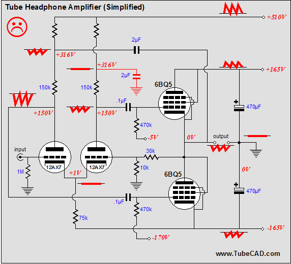
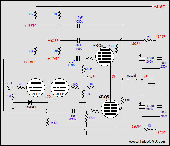
In spite of the little time spent writing the blog entry, the 6BQ5-based headphone amplifier was actually carefully designed, with the part values not casually chosen. The result is that the headphone amplifier acknowledges and anticipates the power supply’s failings, presenting the requisite amount of injected power-supply noise into the output stage to cancel the power-supply noise from the output. Below is the bad schematic that I had posted.
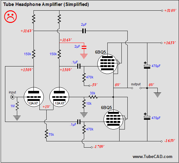
Notice the parts in red. This capacitor serves as a power supply decoupler, filtering away much of the 510-volt power supply rail’s noise. So what’s wrong? Isn’t this what 99% of tube gurus would do? (I was tempted to write 99.9% of tube gurus, but upon some reflection, I realize that percentage would imply that the world holds at least 1,000 tube gurus, a number I doubt.) The problem is that if this decoupling capacitor terminates into ground, the negative power supply rail noise will be superimposed upon the top output triode’s grid signal. How’s that? The differential amplifier’s common cathode resistor attaches to the negative power supply rail and any current variations through this resistor that result from the resistor seeing a varying voltage potential will be relayed to the plate resistors, as they all fall on the same current path.
But in the correct schematic below, we see the decoupling capacitor terminated into the positive-power-supply rail, not ground.
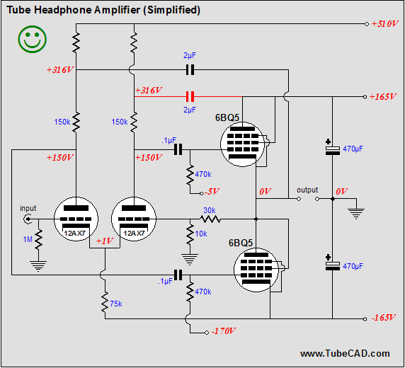
Now the negative power-supply-rail noise will meet and cancel with the positive power-supply-rail noise, as the cathode and plate resistors values were chosen to ensure a noise null at the output. If the cathode resistor were larger, then the output would see positive power-supply-rail noise leaking out; if the resistor were smaller, then the output would see negative power-supply-rail noise leaking out instead. (Ideally, we want injected negative power supply rail noise to equal the positive power-supply-rail noise, so that cancellation is complete.)
How does this trick work? Both the positive and negative power supply rails deviate from being pure DC sources, carrying the rectification noise residue. Fortunately, the noise on each rail is nicely related, equal in magnitude, differing only in being 180 degrees out of phase to each other. (This only holds true when both rails see the same current load, as they do in this amplifier.)
.png)
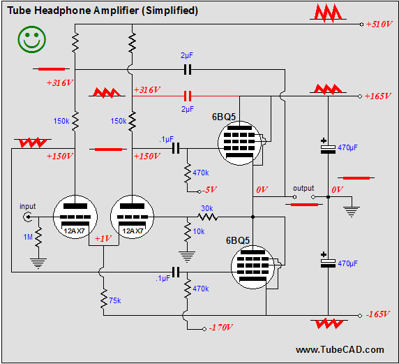
The complete headphone amplifier is shown above. By the way, speaking of noise reduction, I just reread something that I had written in the second issue of the Tube CAD Journal, which is worth repeating every seven years:
Noise, its causes and elimination, will continue to be explored in future issues. The motive is not hard to find.
Noise constitutes a large part of what is condemned as the "tube sound," by those who favor solid-state electronics. Few tube supporters would defend hiss or hum as being euphonic. Noise stands guilty as charged, as it robs the musical experience of subtle nuances. Much of what is magical in a great recording is the air, minute details, and weak hall reverberations that make the recording come alive in our living rooms.
By masking these subtleties, noise reminds us that what we are hearing is not live, but only electronically reproduced. Of course, live performances are often marred by coughing, hacking, talking, creaking chairs, and glass clinking. But this noise is random and sharp, unlike the continuous and dull drone of power supply hum; no one in the audience imagines that he is hearing a reproduced musical event in his living room because of this live noise. (In fact, a few rare recordings so perfectly capture this live noise that its reproduction actually helps to convince us that what we are hearing is live.)
Given the choice between low distortion and low noise, choose low noise. The difference between .1% distortion and .01% distortion cannot be heard; a reduction of noise from -60 dB to -80 dB can. If you want to improve the sound of your tube equipment, lower the noise. Of course, low noise and low distortion are not mutually exclusive and it would definitely be better to have both.
Here is the irony of the situation. Most solid-state gear is very quiet, because of the low distortion race among stereo manufacturers. In order to please the total harmonic distortion meter, an amplifier must be both clean and quiet, as the meter cannot distinguish between distortion and noise. Whereas, the tube audio designer, having no faith in total harmonic distortion measurements, holding to his belief that no meter can beat his ears, forgoes the requirement of extremely low noise operation.
Some tube audio designers are very pessimistic about the noise given off by their designs. They tell us that the vacuum tube is an inherently noisy device and that it is simply not possible to match the solid-state gear in low noise operation. We might believe them, if it were not for counterexample offered by some of the best tube gear: tube microphones, preamps, and amplifiers that do not hum along with the music or hiss like tea kettles. (I built a direct coupled electrostatic headphone amplifier that is so quiet that a friend used to borrow it to evaluate the noise of hand picked transistors for an ultra-low noise preamp he was building. The headphones and amplifier revealed more information about the amount and quality of the noise than did looking into an oscilloscope.) There is simply no excuse for one tenth of a volt of hum from the output of a tube power amplifier.
We are not saying that the tube is just as quiet as the transistor or FET, as, ultimately, it is not; only that much of what is built with tubes could be much quieter.
Amplifying low output MC cartridges reveals the absolute noise floor of a tube. The quietest tube is much noisier than the quietest FET. The 2SK147 FET is eerily quiet; after spending years looking at the 6DJ8's hash noise on an oscilloscope, the flat thin line of noise from the 2SK147 makes one check to see if it is actually connected to the probe. This praise for the FET's low noise does not constitute a wholesale endorsement of the FET's use for all audio circuits, only a recommendation for this limited use: amplifying the micro-volts out of an MC phono cartridge sufficiently to give the vacuum tube a chance to take over.
Making tube equipment quieter requires a solid grasp of where and how the noise is interjected into the output signal.
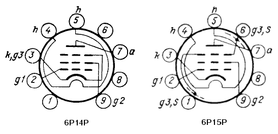
John Atwood has set me straight about the old Svetlana SV83. They are relabeled 6P15P pentodes, a Russian equivalent of an EL83, whereas the 6P14Ps are the Russian equivalent to the EL84. In John’s own words:
I was looking at your latest Tube Cad Journal posting, and I noticed that you implied that the SV83 is equivalent to the EL84. It isn't. It is really a Russian version of the EL83, the 6P15P, which is a video pentode, more similar to a 6CL6 or 6AG7. It may work in a 6BQ5 socket, but the bias points are somewhat different. The pin-outs are also somewhat
different, but if one was aware of both pinouts, the sockets could be wired to be compatible with both.
I have used both the conventional (i.e. consumer-grade) and mil-spec versions of the Russian 6P14P (the mil-spec version has the suffix "EB" in Cyrillic), and both are good, although I especially like the EB version. They sound good, and last a long, long time. I had a quad in my old Heathkit SA-2 amplifier, which I used as my computer sound amp, which ran every day. Before these, I used US-made 6BQ5/7189s and they would last a year or two at the most before one "went critical" and the others were loosing gm. I had the 6P14P-EB tubes in for over 2-1/2 years before I took the amp out of service, and they all tested perfect! These tubes are available on Ebay for about $2.50 each from Russian and Ukrainian sellers. I have gotten some from these sources and have had essentially no problems with the purchases.
And here is an interesting link SV83 Output tube warning! Below is the pinout for the 6P14P and 6P15P pentodes.
Speaking of small, 9-pin power pentodes, I love the 6CW5/EL86, which is a powerful, low-voltage pentode. (The EI version cost only $5 and I am sure that you can still pick up NOS American 6CW5s for just a little more.)
 ET-T3021 ET-T3021
POWER-AMPLIFIER PENTODE
DESCRIPTION AND RATING
FOR AF POWER AMPLIFIER APPLICATIONS
The 6CW5 is a power-amplifier pentode designed for use in the audio-frequency power-output stage of television and radio receivers and in high-fidelity amplifiers.
GENERAL
ELECTRICAL
Cathode—Coated Unipotential
Heater Voltage, AC or DC 6 3 Volts
Heater Current 0.76 Amperes
Direct Interelectrode Capacitances*
Grid Number 1 to Plate 0.6 pf
Grid Number 1 to All 12 pf
Plate to All 6.0 pf
MECHANICAL
Mounting Position—Any
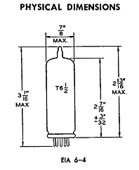
Envelope—T-6½, Glass
Base—E9-1, Small Button 9-Pin Outline Drawing—EIA 6-4
Maximum Diameter 7/8 Inches
Maximum Over-all Length 3-1/16 Inches
Maximum Seated Height 2-13/16 Inches
MAXIMUM RATINGS
DESIGN-CENTER VALUES
Plate Voltage 250 Volts
Screen Voltage 200 Volts
Plate Dissipation 12 Watts
Screen Dissipation 1.75 Watts
Peak Screen Dissipation 6.0 Watts
DC Cathode Current 100 Milliamperes
Heater-Cathode Voltage
Heater Positive with Respect to Cathode 100 Volts
Heater Negative with Respect to Cathode
DC Component 150 Volts
Total DC and Peak 300 Volts
Grid-Number 1 Circuit Resistance
With Cathode Bias 1.0 Megohms

TERMINAL CONNECTIONS
Pin 1—Internal Connection
Pin 2—Grid Number 1
Pin 3—Cathode and Grid Number
3 (Suppressor)
Pin 4—Heater
Pin 5—Heater
Pin 6—Internal Connection
Pin 7—Plate
Pin 8—Internal Connection
CHARACTERISTICS AND TYPICAL OPERATION
AVERAGE CHARACTERISTICS
Plate Voltage 170 Volts
Screen Voltage 170 Volts
Grid-Number 1 Voltage -12.5 Volts
Plate Resistance, approximate 23000 Ohms
Transconductance 10000 Micromhos
Plate Current 70 Milliamperes
Screen Current 5.0 Milliamperes
CLASS A1 AMPLIFIER
Plate Voltage 170 Volts
Screen Voltage 170 Volts
Grid-Number 1 Voltage -12.5 Volts
Peak AF Grid-Number 1 Voltage 9 9 Volts
Zero-Signal Plate Current 70 Milliamperes
Maximum-Signal Plate Current 70 Milliamperes
Zero-Signal Screen Current 5.0 Milliamperes
Maximum-Signal Screen Current 22 Milliamperes
Load Resistance 2400 Ohms
Total Harmonic Distortion,approximate 10 Percent
Maximum-Signal Power Output 5 6 Watts
One reader asked if the 6N1P could be used instead of the 12AX7. It can, but at a price. First of all, it will offer less gain, which means less feedback will be available, which might be important to those seeking the lowest output impedance and distortion. Second, the 6N1P should be run much hotter than a 12AX7, 5mA per triode, not the 1mA that a 12AX7 can get away with. So what’s the big deal, 10mA versus 2mA? The big deal comes in the form of bigger decoupling capacitors. Where the 12AX7-based headphone amplifier only needed 2µF capacitors, the 6N1P version will require five times larger capacitors, 10µF decoupling capacitors. In addition, the two bipolar power supplies may become unbalanced, as the negative power supply rail will be taxed greater than the positive rail, as the current through the differential amplifier starts at the negative power supply rail and ends at the 510V rail. (The workaround might be to use more capacitance on the negative power supply rail than the positive rail.)
In practice, this amplifier may work well enough that these added costs are worth paying. Remember, the 6N1P can be much quieter than the 12AX7.
Another input tube that I would experiment with is the 12BZ7, which also holds a mu of 100, but with half the rp of a 12AX7.
//JRB
|
|
|
|
Kit User Guide PDFs
Click image to download


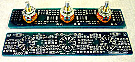
The TCJ Stepped Attenuator
This specially designed stereo attenuator uses three rotary switches and 32 resistors to yield 36 volume positions. This hybrid attenuator uses a combination of both ladder- and series-stepped attenuators. In the first six positions, the attenuator is just a ladder attenuator, with no more than two resistors in the signal path; thereafter, the attenuator uses both a ladder and series configurations, with never more than eight resistors in the signal path. With -2dB decrements, a maximum of -70dB of attenuation is possible; with -1dB decrements, a maximum of -35dB of attenuation.
The center knob controls both channels, and offers six large decrements; the flanking knobs offer six fine decrements for each channel, creating a volume control and balance control in one easy-to-use stepped attenuator.
This clever attenuator uses fewer resistors (only 32) than would be expected from a conventional 32-position stepped attenuator, as two series attenuators would need a total of 72 resistors; and two ladder attenuators would require 140 resistors.
In addition, the PCB holds dual sets of resistor pads, one wide and one narrow, so that axial (composition, wire-wound, and film) and radial (thick-film and bulk-foil) resistors can be used without extra lead bending.
Although designed to go with the Aikido amplifier, it can be used anywhere a high-quality attenuator is needed, whether passive or active. For example, it would make a first-rate foundation to an excellent passive line box.
Designed by John Broskie & Made in USA
Visit our Yahoo Store for more details:
http://glass-ware.stores.yahoo.net/
 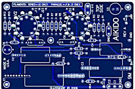
New 9-Pin
& Octal PCBs
High-quality, double-sided, extra thick, 2-oz traces, plated-through holes, dual sets of resistor pads and pads for two coupling capacitors. Stereo and mono, octal and 9-pin printed circuit boards available.
Designed by John Broskie & Made in USA
Aikido PCBs for as little as $24 http://glass-ware.stores.yahoo.net/
Only $12.95
to keep track of your
tube and part collection
TCJ My-Stock DB
TCJ My-Stock DB helps you know just what you have, what it looks like, where it is, what it will be used for, and what it's worth. TCJ My-Stock DB helps you to keep track of your heap of electronic parts. More details.
List all of your parts in one DB.
Add part Images.
One-click web searches for part information.
Vertical and horizontal grids.*
Create reports as PDFs.*
Graphs added 2D/3D: pie & bar.*
More powerful DB search.
Help system added.
Editable drop-down lists for location, projects, brands, styles, vendors and more.
*User definable
For more information, please visit:
Only $9.95
to start designing tube-based
crossovers and much more...
TCJ Filter Design
The Tube CAD Journal's first companion program, TCJ Filter Design lets you design a filter or crossover (passive, solid-state or tube) without having to check out thick textbooks from the library and without having to breakout the scientific calculator. This program's goal is to provide a quick and easy display not only of the frequency response, but also of the resistor and capacitor values for a passive and active filters and crossovers.
TCJ Filter Design is easy to use, but not lightweight, holding over 60 different filter topologies and up to four filter alignments:
Bessel,
Butterworth,
Gaussian,
Linkwitz-Riley.
While the program’s main concern is active filters, solid-state and tube, it also does passive filters. In fact, it can be used to calculate passive crossovers for use with speakers by entering 8 ohms as the terminating resistance. Click on the image below to see the full screen capture.
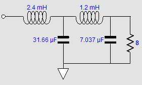
Tube crossovers are a major part of this program; both buffered and un-buffered tube based filters along with mono-polar and bipolar power supply topologies are covered. Available on a CD-ROM and a downloadable version (4 Megabytes).
|