| John Broskie's Guide to Tube Circuit Analysis & Design |
|
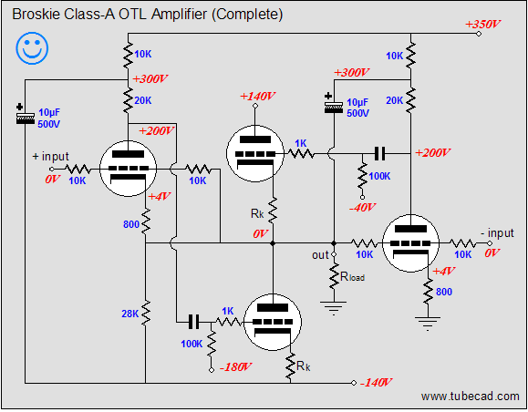
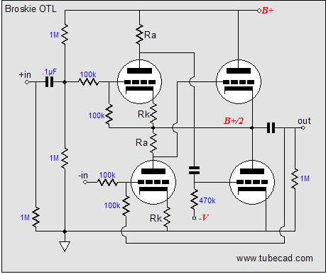
07 January 2007  My last post held a new OTL topology, which I egotistically named the Broskie OTL. The topology was illustrated with triodes as the active devices, but there’s no reason that pentodes, UBT FETs, or depletion-mode MOSFETs could not be used in the triode’s stead. In fact, with some fiddling, BJT transistors could be used. My last post held a new OTL topology, which I egotistically named the Broskie OTL. The topology was illustrated with triodes as the active devices, but there’s no reason that pentodes, UBT FETs, or depletion-mode MOSFETs could not be used in the triode’s stead. In fact, with some fiddling, BJT transistors could be used.
Think of topology as the circuit’s skeleton, upon which the components adhere, much like flesh and hair adorn our skeletons. (The largest failing that most tube-loving neophytes make is that they cannot see a circuit’s skeleton, its topology, seeing only the 2A3 or 5687 and resistors and capacitors; even worse off are those who only see part brands—the RCA NOS tubes and Allen Bradley carbon-film resistors and Black Gate capacitors—not knowing what a triode or resistor or capacitor does in a circuit.) Eight ohms is a horridly-low impedance for any tube to drive directly. In that perfect world in our dreams, fantastic-sounding 1,000-ohm loudspeakers are both cheap and common, allowing us to build fantastic-sounding and inexpensive OTL amplifiers (imagine a 2A3-based OTL). Alas, no: we are stuck with eight-ohm loudspeakers that are closer to five ohms in actual use. Even low-impedance headphones are a pain to drive directly with a tube OTL output stage. So, after some careful consideration, the hybrid option looks better and better.
Hybrid OTLs
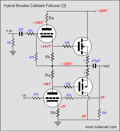
The Broskie cathode follower uses only two triodes and converts a balanced input signal into a single-phase output signal. Surprisingly, a single 6DJ8 used in this topology can beautifully drive a 300-ohm headphone, such as the Sennheiser and AKG models. Driving 8-ohm loudspeakers, or even Grado 32-ohm headphones, will take much more muscle. The 6DJ8 can be replaced by a beefier tube, such as the 6AS7, 6H30, 6C33, 12B4, 5687...but none of these tubes is up to the task of driving inefficient loudspeakers directly. Compared to modern-production, poor-quality vacuum tubes, even the best MOSFETs are dirt-cheap; for example, the excellent BUZ901 cost less than $10 each and mediocre IR HEXFETs cost only a few dollars each.
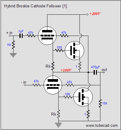
In the above schematic, we see a pair of N-channel MOSFETs attached to the Broskie cathode follower. The 470µF coupling capacitor implies that this amplifier's intended load is 32 ohms, which means that the MOSFETs can be run hot, ensuring pure class-A operation over a large voltage swing. The MOSFETs should be matched and the cathode resistors, RK, should be selected carefully to guarantee that the MOSFETs are biased correctly and that the triodes conduct enough current to overcome the MOSFETs’ large input capacitance. (I would strive for at least 8mA of current through the triodes and 50mA through the MOSFETs.) As each triode conducts more, its MOSFET also conducts more, augmenting the triode’s contribution, so that both devices work into the load. Of course, P-channel MOSFETs can be used instead, with suitable rearrangements.
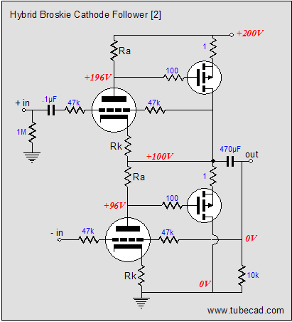
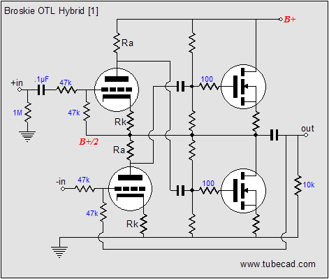
Heck, with suitable rearrangements, both N- and P-channel MOSFETs can be used:
(Feel free to imagine Sanken or ON Semiconductor power transistors in place of the MOSFETs.) Now, while the two MOSFETs look more symmetrical, their input capacitance is not symmetrically balanced in the circuit. Thus, I would add small trim capacitors to the topmost plate resistor and the bottommost cathode resistor, so that all the resistors see a same shunting capacitance. So what do I think of these hybrid OTL topologies? Not much. Yes, they all work and many would like the sound they would produce. But what troubles me about all these topologies is that the tubes and the MOSFETs conduct in phase; in other words, when the triode increases its current conduction, the paralleled MOSFET does too; and when the triode decreases its conduction, so does the MOSFET. Thus, the nonlinearities add together, rather than cancel. So how do we get anti-phase conduction and with it, a more linear transfer function?
Broskie OTL hybrid amplifiers
Replacing the output tubes with power MOSFETs requires making the choice between the rare depletion-mode and the common enhancement-mode MOSFETs. Like transistors, the N-channel enhancement-mode MOSFETs need to see a positive gate voltage relative to their sources to conduct at all; like the triode, the depletion-mode MOSFETs can conduct with a negative gate voltage. Sounds great, lets use depletion-mode! Well, it's not great, as out of the thousand types of power enhancement-mode MOSFETs only a handful are audio-grade; out of the handful of depletion-mode MOSFETs, none. (And to be frank, DC coupling is beautiful to look at in a schematic, but a real pain to realize in reality, as the slightest current imbalance often leads to an extreme voltage imbalance. So even if audio-grade depletion-mode MOSFETs were readily available, I would still use some form of capacitor coupling between tube and solid-state stages.)
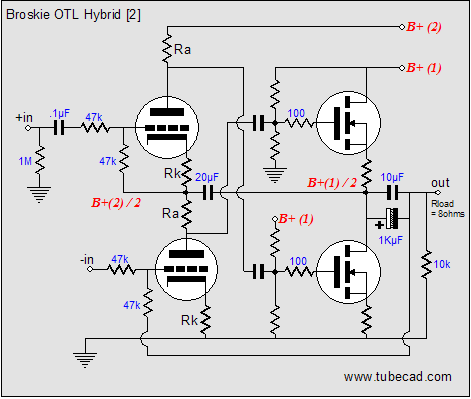
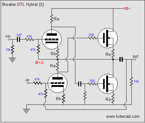
In the above schematic, we see enhancement-mode MOSFETs used in place of the output tubes. Each MOSFET connects to its own two-resistor voltage divider, which sets the idle current through the output MOSFETs. My fear is that an imbalance in idle current will throw the output off the B+/2-midpoint voltage. My second concern is that the either the tubes will not get enough B+ voltage or that the MOSFETs will experience too much source-to-drain voltage. The workaround to both of these problems is shown in the schematic below.
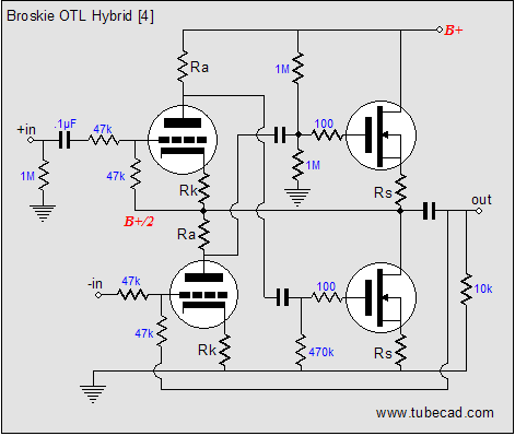
Now two B+ voltages are used, one for the tubes and one for the MOSFETs. Imagine +300V for the triodes and +40V for the MOSFETs. The two-resistor voltage dividers find different terminations and the output stage should more readily center at one-half the MOSFET output stage B+ voltage. The output coupling capacitor has been replaced with a huge-valued electrolytic and a large-valued film capacitor. Why? Given a robust-enough power supply and power MOSFETs, this hybrid can now drive 8-ohm loads. What’s missing is a balanced input stage, which could be made up from a differential amplifier or a grounded-cathode amplifier and a split-load phase splitter. Just for kicks, what if we had wanted to use depletion-mode MOSFETs (although no stellar audio-grade depletion-mode MOSFETs exists)? After all, the triodes are in charge of the MOSFETs’ output. The schematic below shows such a hybrid amplifier.
Once again, I am troubled by the direct coupling between the top MOSFET and the bottom triode’s plate resistor, as a current imbalance can lead to an extreme voltage imbalance. The source resistors help, but an additional coupling capacitor and two-resistor voltage divider guarantees the B+ voltage division.
By the way, note how the depletion-mode MOSFET’s schematic symbol differs from the enhancement-mode MOSFET’s. Actually, the more I look at the above schematic, the more I like it, as it has the look of a good headphone amplifier or a muscular line stage amplifier. Now, if only I could find my stash of Supertex DN2535 depletion-mode MOSFETs (the TO-220 package is the version to get).
Next time //JRB
|
Only $9.95
Download or CD ROM www.glass-ware.com
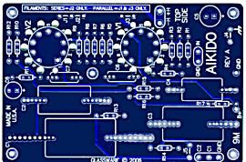
High-quality, double-sided, extra thick, 2-oz traces, plated-through holes, dual sets of resistor pads and pads for two coupling capacitors. Stereo and mono, octal and 9-pin printed circuit boards available.  Aikido PCBs for as little as $24 http://glass-ware.stores.yahoo.net/
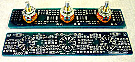
The TCJ Stepped Attenuator The center knob controls both channels, and offers six large decrements; the flanking knobs offer six fine decrements for each channel, creating a volume control and balance control in one easy-to-use stepped attenuator. This clever attenuator uses fewer resistors (only 32) than would be expected from a conventional 32-position stepped attenuator, as two series attenuators would need a total of 72 resistors; and two ladder attenuators would require 140 resistors. In addition, the PCB holds dual sets of resistor pads, one wide and one narrow, so that axial (composition, wire-wound, and film) and radial (thick-film and bulk-foil) resistors can be used without extra lead bending. Although designed to go with the Aikido amplifier, it can be used anywhere a high-quality attenuator is needed, whether passive or active. For example, it would make a first-rate foundation to an excellent passive line box. Visit our Yahoo Store for more details: http://glass-ware.stores.yahoo.net/
The Tube CAD Journal's first companion program, TCJ Filter Design lets you design a filter or crossover (passive, solid-state or tube) without having to check out thick textbooks from the library and without having to breakout the scientific calculator. This program's goal is to provide a quick and easy display not only of the frequency response, but also of the resistor and capacitor values for a passive and active filters and crossovers. TCJ Filter Design is easy to use, but not lightweight, holding over 60 different filter topologies and up to four filter alignments: While the program’s main concern is active filters, solid-state and tube, it also does passive filters. In fact, it can be used to calculate passive crossovers for use with speakers by entering 8 ohms as the terminating resistance. Click on the image below to see the full screen capture.
Tube crossovers are a major part of this program; both buffered and un-buffered tube based filters along with mono-polar and bipolar power supply topologies are covered. Available on a CD-ROM and a downloadable version (4 Megabytes). Download or CD ROM
|
|||
 Once I have come up with a good skeleton, I start looking for different technologies to encase the topologies. In fact, before the ink dries on my sketch pad, I begin wondering how I can translate my all-tube circuits into silicon, or vice versa. I make these electronic translations because I can and because I find them fun, not because I think that they necessarily sound better. In a perfect world, we would use perfect tubes and be happy. As our world isn’t even a semifinalist in the perfection contest, we use what we have and try to ignore the rest. The philosophy of "making do" leads to hybrid designs, as each technology has its own failings, which we hope to erase by wedding dissimilar technologies. You know the glossy-ad-copy argument, tubes for voltage amplification and solid-state devices for current delivery. (Believe it or not, a few brave audio designers have offered us solid-state front-ends for precision and tube-based output stages for emotion, which at least ignores the allure of cheap solid-state output devices.)
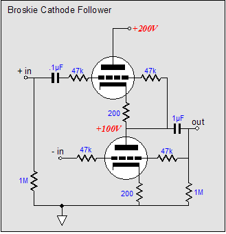


| www.tubecad.com Copyright © 1999-2007 GlassWare All Rights Reserved |