|
25 March 2007

One hundred blog entries can seem like a lot or a little, depending on your perspective. If I had the sense to not fill each entry with several subtopics, giving each topic its own post, my total would be at least three times bigger. In fact, if did what I would like to do—post a blog entry everyday—I would be celebrating my one thousandth post, not my one hundredth.
If only it wasn’t so time consuming. The only readers who truly know how much work it takes to put out a lengthy blog are the ones who are writing their own. The others keep asking me why I don’t post more often :{
On a happier topic, you can now buy the best printed circuit boards based on the cleverest circuits with PayPal at the GlassWare Yahoo Store. Now, that’s worth celebrating.
Now accepting 
Hello All,
I would like to notify you that we are beginning registration for the next Randall Museum EF86 Linestage class. The Fall session successfully completed a dozen linestages ahead of schedule. The Spring class session begins Saturday, April 14th and runs through Saturday, June 9th.
Class meets from 1:30 to 4PM in the Randall Room on the Mezzanine level above the museum lobby. All the materials needed will be provided to each class member as a complete kit. Tuition for the class is $135 and the materials fee is $425. The materials include a Sovtek or ValveArt (5AR4 rectifier) and a matched pair of Svetlana EF86 tubes. The results from the first class were outstanding. Registration is limited to 12 students. Please go to the Randall Museum link to download the registration form. Mail your completed form with a check for tuition to the Randall Museum at 199 Museum Way, SF, CA 94114. Materials fees will be collected at the first class meeting. Hope to see you here in April. Feel free to email with any questions. Thank you.
Regards,
Chris

Randall Class Flyer & Registration Form
Chris Boettcher
Executive Director
Randall Museum
199 Museum Way
San Francisco, CA 94114
“Let me ruin your life,” is what I said on the phone the other day to Bill Perkins of PEARL Audio fame. Stop and think about it: What would it take ruin someone’s life? What could I tell him that would be so devastating? Something big and really nasty? Often, yes, but not always. No, I wasn’t inviting him to join a religious multi-level marketing scam like Nescientology, or a kooky non-religious cult like Scamway or share-the-mortgage-but-not-the-profits, time-share condos. None of the above, as my only crime was to inform Bill about Google’s patent search engine.
Now, I fully understand that for most people finding out about this free service from Google would only provoke large yawns (Google porn search on the other hand…). But for someone like Bill or me—someone who loves digging into old electronic-theory treasures, being able to search through the US patent system’s archives with keywords such as “vacuum tube amplifier” and “low noise” —that is what sleep-deprivation-from-never-getting-off-the-computer dreams are made of. Here are just a few unsystematic examples:
Audio-Amplifier
Patent number: 2815407
Filing date: Oct 4, 1956
Issue date: Dec 3, 1957
Inventor: David Hafler
Abstract: The present invention relates generally to audio amplifiers of the high fidelity type, and more particularly to high fidelity high-gain audio amplifiers having novel feed-back circuits for increasing the band-width of the amplifier response, and the stability of the amplifier over its response band.
It has become conventional, in amplifier design, to provide flat frequency response over the band 20C.P.S.-20kc., and distortion figures .1% at normal listening levels and less than I% at rated output are routine. These specifications do not invariably correlate with audible performance.
Several important factors in addition to low distortion and flat frequency response contribute to listening quality. One of these is transient performance. Good transient performance entails critical damping of an amplifier, so that peaky or pulse-like signals do not cause oscillatory surges which appear at the loud-speaker as spurious signals. Good transient response also requires wide pass-band so that signals of steep wave front are not distorted, and so that no overshoot or ringing will occur, and phase shift be minimized. The recited characteristics are all interrelated with the stability characteristics of an amplifier wider feed-back conditions and the regulation characteristics of the power supply employed. If an amplifier is on the verge of instability when speaker loaded, it cannot exhibit good transient performance. If power supply voltages shift as power output varies, there is a change of operating conditions. under dynamic conditions, which entails distortion.
A further requirement is adequate power handling capacity. High power requirements are due to low speaker efficiency, especially in the case of high quality speakers. At frequency extremes the impedance characteristics of loud-speaker systems change from their nominal values, causing severe mismatch and a consequent reduction in undistorted output power of the amplifier.
Look familiar? It should, as this is the famous Dynaco ST-70 circuit. Alan Blumlein patented the screen-grid feedback principle (ultra-linear operation of pentode output tubes) in Britain in 1937, UK Pat. No. 496,883, but that didn’t stop Hafler from doing the same. How can that be?
Well, I know that the patent office is staffed by the greatest geniuses in the world; that these polymaths know all that can be created and all that has been created; and that if you receive a patent, then your invention is both original and perfect. Of course, there are some spoilsport types out there that claim that you could resubmit Blumlein’s patent today under your name and get it approved, but these killjoys just don’t have the creativity or the $5,000 it takes to get a patent.
Nonetheless, the patent is interesting to read, as David had many tricks hidden in his simple power amplifiers.
Direct Coupled High Fidelity Amplifier
Patent number: 2777020
Filing date: Jun 22, 1951
Inventor: Joseph F. Dobosy
Abstract: My invention relates to electronic amplification and has for its principal object producing efficient, high fidelity amplification of electrical voltage and power over a wide range of frequencies.
A further object is to provide a high fidelity amplifier with a high degree of reliability and capacity to deliver high overloads at frequencies down to substantially zero frequency or direct current as well as in the video region of the frequency spectrum.
A further object of the invention is to obtain prompt and faithful response to transient conditions and high fidelity amplification of speech and other signal. of constantly varying frequency and amplitude which make the transient characteristics of the amplifier of as great importance as the characteristics under steady state conditions.
Another object of the invention is to make the magnitude and phase of the output voltage substantially independent of load impedance variations that would normally be encountered and to provide a generator having the power to be the principal factor in the determination of magnitude and phase of the output voltage.
Still another object is to apply corrective feedback for the reduction of distortion without creating undesirable transients.
A further object is to eliminate the necessity for direct-current flow in the toad circuit, transformer coils, choke coils or devices which may be subject to magnetizing or to other unilateral effects.
An additional object is to permit grid excitation to enter the positive grid region without creating distortions or transients in the coupling circuits....
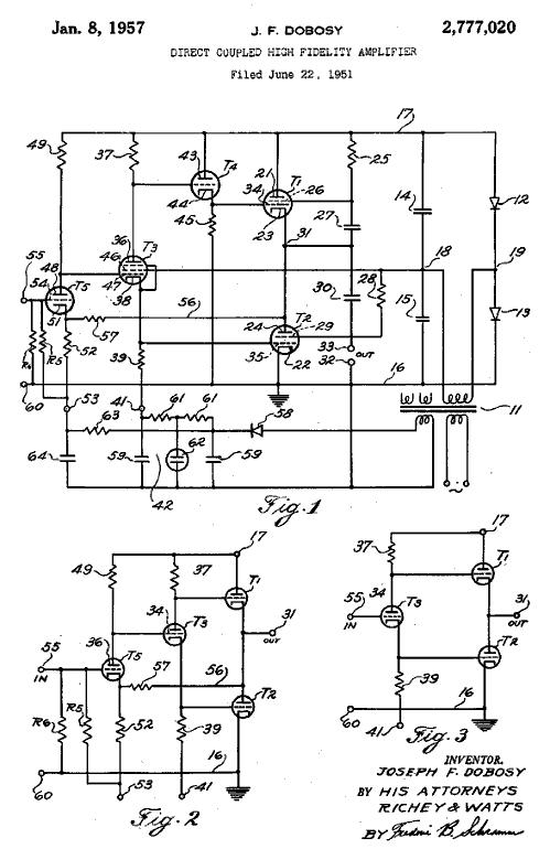
An interesting OTL amplifier design that is well worth reviewing in detail. Note the pentode-based phase splitter and the DC-coupled feedback connection to the output.
Tube Amplifier Fat Emulation Structure
Patent number: 5761317
Filing date: Mar 4, 1996
Issue date: Jun 2, 1998
Inventor: Eric K. Pritchard
Abstract:
This disclosure shows the solid state emulation of elements of a thermionic emission device amplifier which distinguish it from solid state amplifiers: the output impedance of transformer impedance with plate resistance, the transfer function coupling from the driver tube to the output tubes, the non-linearity of the output tubes, the compression created by the power supply droop, the inclusion of "fat" from the power supply, bias shifting of the input, and driving the input from a non-linear network. This disclosure also depicts advantageous features not found in tube amplifiers: a means for turning it down and maintaining the tone by maintaining the interrelationships within the amplifier and fat creation from the amplifier output and from external sources. This disclosure is based upon the novel use of controlled gain and controlled impedance means.
“All the artery-choking fat and none of the nutrition of vacuum tubes,” now there’s a marketing slogan. Do a search for solid-state tube-sound-emulating power amplifiers and be prepared to need a few strong drinks. The premise is always the same: tube amplifier distort grossly and hum and hiss horrendously and that’s why they sound so much better than solid-state amplifiers. Well, you can see the logic, as it’s just like fat, short, bald men being so much more handsome than their slender, tall, hair-topped brothers. Wait a minute, something went wrong here; it’s just like short-tempered, shrill-voiced, angst-ridden women are so much more appealing… never mind—obviously, I am just not getting something here.
Hybrid thermionic valve and solid state audio amplifier
Patent number: 6140870
Filing date: May 18, 1998
Issue date: Oct 31, 2000
Inventor: Erick M. Cook
Primary Examiner: Khanh Van Nguyen
Abstract: Hybrid thermionic valve and solid state audio amplifier. A complete tube amplifier is scaled to produce a relatively low power yet also retain its small and large signal distortion characteristics. The output of the scaled amplifier is amplified by a relatively linear solid state amplifier. In one embodiment of the invention, a plurality of tube amplifiers are coupled in parallel and input to a mixing circuit for selectably mixing the outputs of the tube amplifiers and providing the mixed outputs to the solid state amplifier.
Not as fattening as most tube amplifiers, Mr Cook half-cooked effort gets a C- minus for too much effort for so little results.
Vacuum tube and MOSFET transimpedance amplifier
Patent number: 5017884
Filing date: Nov 1, 1989
Issue date: May 21, 1991
Inventor: Aado J. Perandi
Abstract: An improved transimpedance amplifier includes a common cathode-connected vacuum tube first stage, coupled to a common-drain-connected MOSFET second stage, and an optional common drain-connected MOSFET third stage. Preferably, capacitive feedback is coupled from the output of the second stage to the input of the vacuum tube stage, to control the transimpedance of the amplifier. The circuit takes advantages of the low stray inter-electrode capacitances, low delay and transit times of the vacuum tube and the high transconductance of the MOSFET second and optional third stages, in a way complementary to one another to form a high transimpedance amplifier whose characteristics are controlled almost exclusively by the feedback capacitance or other feedback impedance, rather than by gain and stray capacitance terms of individual devices. The resulting transimpedance amplifier is useful in a number of applications, for example, in audio preamplifiers and audio power amplifiers.
At first I thought that the above patent was too obvious, but after reading into it, I have a higher regard for the effort. The above schematic is only one of many and the others are all more interesting. Do check it out.
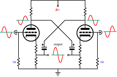
Now for something really interesting. The following patent holds a topology that not one solder slinger in ten will recognize, yet this topology is famous enough to have a name and a huge following. See if you can spot it.
DIFFERENTIAL AMPLIFIER
Patent number: 3156873
Filing date: Aug 12, 1960
Inventor: T. R. WILLIAMS
Abstract: This invention relates to differential amplifiers and particularly to an amplifier capable of providing two output signals, one of which is proportional to the difference of two input voltages and the other of which is the negative counterpart of the first.
The use of differential amplifiers is well established in the electronic art wherever it is necessary to obtain an output voltage which is proportional to the difference between two input voltages, such as in computing machines. The present invention is especially useful in applications in which a differential signal and/or its negative counterpart are desired, for example, where the differential signal is to be observed visually by means of an oscilloscope. Each of the two signals can here be applied to a different one of the oscilloscope deflection plates.
The objects and advantages of the present invention arc accomplished by employing a pair of identical amplifiers in a push-pull arrangement, each of the amplifiers amplifying a different input signal, and feeding back all, or a portion of the A.C. signal variation across the load of each stage to the cathode circuit of the other stage. In a preferred embodiment of the invention, the output signals are obtained from the points in the cathode circuits of the stages to which the A.C. signal variations arc fed back.
Ok, ready for a hint? The latent topology is not a single-ended one, being, instead, a push-pull configuration. Still, cannot see it? The above schematic shows a circlotron amplifier made up from a single power supply and some large decoupling (or is re-coupling a more apt description) capacitors and two plate resistors. Start by ignoring the Miller-effect neutralizing variable capacitors, then focus on capacitors Ca, numbers 56 and 58. If that does not do the trick, then look at it redrawn.
Terminating the bottom cathode resistor into a negative power supply would be a good circuit upgrade. And while we are at it, the plate resistors could be replaced by a center-tapped inductor, as could all the cathode resistors. But then, we already covered that here long ago, but not 47 years ago. By the way, hasn’t some German or Swedish high-end company recently patented this 47-year old topology? Or, at the very least, reinvented it?
Circlotron you say? Does that mean that this circuit must run in class-A because of it? In other words, can I run a trickle current through the output tubes and still claim to have a class-A amplifier, no matter what the load impedance or the peak output current swings? Well, I do not know about all that, but I understand that if you pull on your shoestrings really hard, you can lift yourself up as high as you want to fly.
By the way, to my friend Bill and several hundred other techno-archeologists, sorry for ruining your life, or, at least, for causing you to lose any more sleep.
//JRB
|
|
|
|
Kit User Guide PDFs
Click image to download


Only $12.95
to keep track of your
tube and part collection
TCJ My-Stock DB
TCJ My-Stock DB helps you know just what you have, what it looks like, where it is, what it will be used for, and what it's worth. TCJ My-Stock DB helps you to keep track of your heap of electronic parts. More details.
List all of your parts in one DB.
Add part Images.
One-click web searches for part information.
Vertical and horizontal grids.*
Create reports as PDFs.*
Graphs added 2D/3D: pie & bar.*
More powerful DB search.
Help system added.
Editable drop-down lists for location, projects, brands, styles, vendors and more.
*User definable
For more information, please visit:
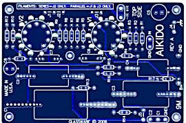
New 9-Pin & Octal PCBs
High-quality, double-sided, extra thick, 2-oz traces, plated-through holes, dual sets of resistor pads and pads for two coupling capacitors. Stereo and mono, octal and 9-pin printed circuit boards available.
Designed by John Broskie & Made in USA
Aikido PCBs for as little as $24
http://glass-ware.stores.yahoo.net/

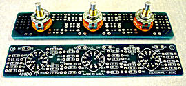
The TCJ Stepped Attenuator
This specially designed stereo attenuator uses three rotary switches and 32 resistors to yield 36 volume positions. This hybrid attenuator uses a combination of both ladder- and series-stepped attenuators. In the first six positions, the attenuator is just a ladder attenuator, with no more than two resistors in the signal path; thereafter, the attenuator uses both a ladder and series configurations, with never more than eight resistors in the signal path. With -2dB decrements, a maximum of -70dB of attenuation is possible; with -1dB decrements, a maximum of -35dB of attenuation.
The center knob controls both channels, and offers six large decrements; the flanking knobs offer six fine decrements for each channel, creating a volume control and balance control in one easy-to-use stepped attenuator.
This clever attenuator uses fewer resistors (only 32) than would be expected from a conventional 32-position stepped attenuator, as two series attenuators would need a total of 72 resistors; and two ladder attenuators would require 140 resistors. In addition, the PCB holds dual sets of resistor pads, one wide and one narrow, so that axial (composition, wire-wound, and film) and radial (thick-film and bulk-foil) resistors can be used without extra lead bending.
Although designed to go with the Aikido amplifier, it can be used anywhere a high-quality attenuator is needed, whether passive or active. For example, it would make a first-rate foundation to an excellent passive line box.
Designed by John Broskie & Made in USA
Visit our Yahoo Store for more details:
http://glass-ware.stores.yahoo.net/
Only $9.95
to start designing tube-based
crossovers and much more...
TCJ Filter Design
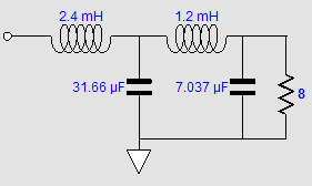
The Tube CAD Journal's first companion program, TCJ Filter Design lets you design a filter or crossover (passive, solid-state or tube) without having to check out thick textbooks from the library and without having to breakout the scientific calculator. This program's goal is to provide a quick and easy display not only of the frequency response, but also of the resistor and capacitor values for a passive and active filters and crossovers.
TCJ Filter Design is easy to use, but not lightweight, holding over 60 different filter topologies and up to four filter alignments:
Bessel,
Butterworth,
Gaussian,
Linkwitz-Riley.
While the program’s main concern is active filters, solid-state and tube, it also does passive filters. In fact, it can be used to calculate passive crossovers for use with speakers by entering 8 ohms as the terminating resistance. Click on the image below to see the full screen capture.
Tube crossovers are a major part of this program; both buffered and un-buffered tube based filters along with mono-polar and bipolar power supply topologies are covered. Available on a CD-ROM and a downloadable version (4 Megabytes).
|