| John Broskie's Guide to Tube Circuit Analysis & Design |
09 September 2007 
Don't get me wrong; I am not nostalgic for the CD. Since the day that I first read of the CD’s creation, I have been troubled. Why, I wondered, had the CD been restricted to a stereo format? Mono, stereo, three-channel, and even four-channel options could have been implemented, as a header file on the CD would tip off the player how many audio tracks the CD held. Imagine mono, spoken-word CDs that played for over two hours or three-channel CDs that played for 45 minutes; even a 30-minute four channel CD would be fun. In addition, I could not understand why the CD format, a digital format, did not take greater advantage of its digital nature by providing a wealth of additional track and album information on each CD, for example the liner notes, production details, and lyrics (such an addition would only consume 0.0001% of the CD's capacity). Then, finally, there is the CD’s lackluster sound. Did you know that if you look in the American Heritage Dictionary, under the word, “dead,” you will find the eighth meaning includes the CD as an example:
No, my view is that the CD is not quite dead yet; in fact, it could bounce back, although such a future is unlikely. It will only recover if the RIAA and the five major labels realize that all the cream has long ago been sucked dry and that the CD can only continue to be sold if its price falls in in line with its actual value, say $3 to $4. Making CDs is cheap, as a CD cost only a few dimes to produce; in fact, I wouldn’t be surprised if the those dreadful plastic cases and paper inserts cost more than the CD; and while recording studio time might be expensive if you belong to a garage band, compared to movie production costs, however, music production costs are insignificant. Let's be frank, today, recorded music is no more than a commodity, like soy beans, pork bellies, advertising, or porn. Furthermore, the days of recorded music’s entertainment monopoly are long gone. CDs are only one out a hundred possible objects capable of entertaining, with computer games, video game consoles, cable programming, DVDs, the Web, satellite radio, and many more distractions clamoring for our attention and extra cash. The truth of the situation is that CD sales fell long before the birth of the iPod and, even today, downloads represent only a small portion of music sales, albeit a steadily growing portion. The irony is that CD prices had begun to fall naturally over ten years ago (remember the sub-ten-dollar CDs at Target and Wal-Mart and the CD price war that ran between the two), but the RIAA and major labels reversed the evolutionary trend by forcing artificially high prices (remember settlement and the 140M paid out in fines about five years ago), thereby reducing sales to a trickle and prematurely killing the CD—and Tower Records. Of course, the RIAA and the big five labels will argue that CDs are a bargain, that they should cost twice as much because of inflation... that they do not make nearly enough money in other words. As the Spanish say, pobrecito; it must be tough selling something that cost 25 cents for $18. How strange it is to see DVDs, holding fairly good recent movies—which offer two hours of video, multilingual support, plus bonus materials—sell for only $5 at Target, but not see any CDs for less than $10, even when most of the CDs hold fairly old or bad music. Who, other than some RIAA hack, could claim that the DVD is lower tech or cheaper to produce than the CD or that any movie could be cheaper to produce than the most elaborate music CD? Am I batty? How can CDs be sold for only $3 to $4, when downloads cost 99 cents each? They can’t, at least not under the music cartel’s way of thinking. But then downloads are overpriced as well. My prediction is that downloads will only begin to really soar once their price per track falls to 25 cents—or even less. Particularly classical music. Classical music? Each classical music label is sitting on a huge library of recordings, very few of which are currently in their catalogs. One day, all classical-music labels will realize that it is better to sell 30 downloadable albums for $2 each than one CD (or one CD's worth of downloads) for $17. This argument is even more compelling when the download consists of an album not currently in production, or ever likely to be in production again. At the other music extreme, Paul McCartney is lauded for his bold move to sell his new rock CD, Memory Almost Full, in Starbucks cafes, but what would have been truly bold would have been to sell the album as a download for only $4. (Last time I looked, Sir Paul had sold 250,000 CDs in America; had he offered a $4 downloadable album, he might of sold 10,000,000, which translates into $39,900,000 of profit compared to the "maybe" $1,000,000 he made from the CD sales, as servers and bandwidth are cheap commodities today.) Who will be first? *Excerpted from American Heritage Talking Dictionary. Copyright © 1997 The Learning Company, Inc. All Rights Reserved.
Alternate Approach to RIAA EQ
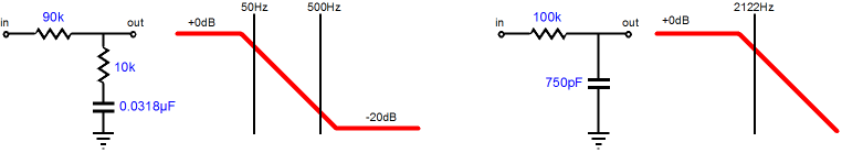
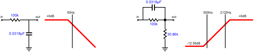
The shelving network effectively boosts low frequencies below 50Hz by +20dB, by attenuating frequencies above 500Hz by -20dB. (In other words, the shelving network incurs a -20dB insertion loss for above frequencies above 500Hz; it is passive after all. Thus, a +40dB, passive-EQ, phono preamp actually requires an initial gain of +60dB, since -20dB will be lost in the equalization network.) A low-pass filter based on 75µs translates into a transition frequency of 2122Hz. (The easy way to decode time constants into frequencies is to divide 159155 by the time constant in µs; for example, 159155 / 318 = 500.5Hz.) But we could just as easily split the equalization task up differently, by giving the 3180µs time constant to a 50Hz low-pass filter and combine the 318µs and 75µs time constants into one shelving network that transitions at 500Hz and 2122Hz. The big difference is that this shelving network attenuates low frequencies, while passing high-frequencies.
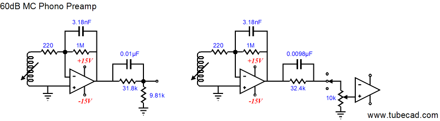
Both passive equalization approaches yield the same flat response from the LP, but this second approach offers a larger insertion loss, -32.55dB versus -20dB. This may not be much of a difference for solid-state circuits, with their easy high gain, but is quite substantial for simple tube-based designs. This second approach, however, presents us with an easy means to create a low-frequency tone control by shifting the 50Hz pole up and down in frequency. The greater the shift, the bigger the boost or cut in low bass frequencies. (Yes, this tone control would only apply to record playback, but then I came up with this approach 25 years ago, when I only listened to records.) If the 2122Hz low-pass filter is varied in the conventional split RIAA EQ configuration, the highs are cut or boosted in a similar fashion. 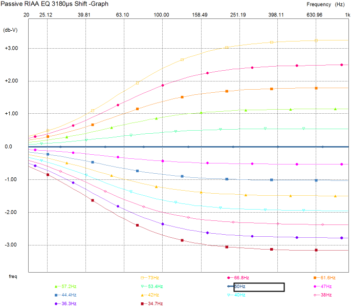 Implementing this equalization configuration can take many forms. For example, below is an active/passive solid-state implementation.
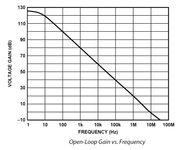
The active portion takes care of the 50Hz low-pass filter, while the passive portion handles the 500Hz-2122Hz shelving network. Why this configuration? I like the idea of the OpAmp’s output steadily falling off at -6dB per octave above 50Hz, as its intrinsic, open-loop frequency response also falls off at -6dB per octave above some low frequency, say 5Hz.
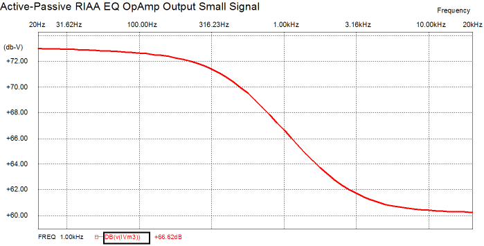
This means that the OpAmp will apply a constant feedback margin across the audio band and it will be better behaved at high-frequencies because of it. Why do I show the circuit twice? The rightmost variation shows how the volume potentiometer can be included in the shelving network. (I know that many are fretting over the inverting OpAmp configuration. Yes, the 220-ohm resistor’s resistance is placed in series, not in parallel, with the MC cartridge’s reactance and DCR, making this approach a tad more noisy; but the added noise has a different sonic texture because of the inverse RIAA equalization.) How well does this circuit work? According to SPICE, quite well. The graph below shows the output from the OpAmp.
The next graph shows the shelving network’s transfer function.
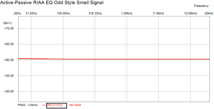
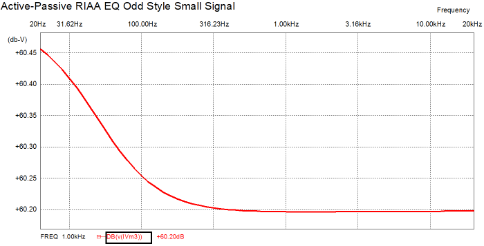
The combined total frequency response is shown below.
Well, the above graph is what you would see a in a brochure or glossy-magazine review; the same trace under greater resolution is shown below.
Tweaking the part values a tad would probably flatten the curve at the left.
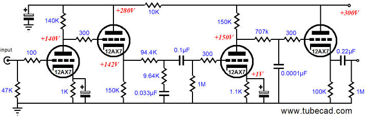
Tubes! Where are the Tubes!
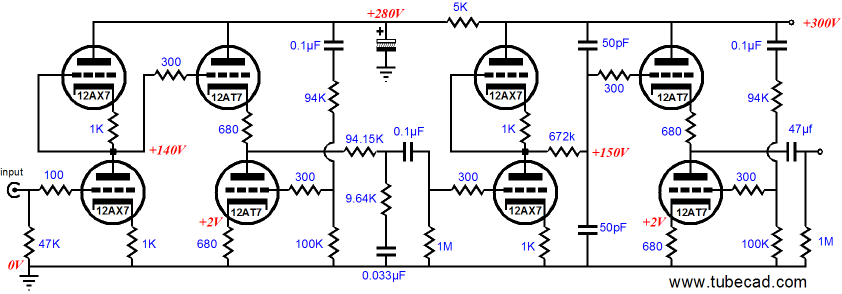
I must admit that I derive a great deal of perverse pleasure from all the head scratching this circuit is bound to provoke. For example, where is the coupling capacitor between gain stages? As far as high-frequencies are concerned, the coupling capacitor is there; but as far as DC and low-frequencies are concerned, it’s not present, as we see only a two-resistor voltage divider. Now, let’s compare the above schematic to the one below, which implements the standard approach to splitting the equalization function.
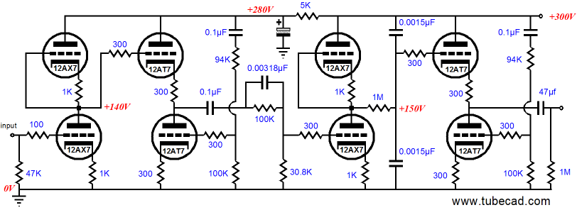
The coupling capacitor between gain stages is not hard to find, but the rest of the circuit does not topologically look that different. The 2122Hz low-pass filter that feeds the final cathode follower also works to reduce tube noise along with equalizing the output signal. What cannot readily be seen is that this circuit will offer +12dB more gain that the circuit above it, because of the deeper attenuation produced by the 500Hz-2122Hz shelving network in between gain stages in the circuit above it. What interested me in resurrecting the above circuits is the possibility of using the same RIAA equalization arrangements in an Aikido-based phono preamp. Since the Aikido amplifier offers low distortion and a great PSRR figure, it would seem a natural basis for a great tube phono preamp. Taking the schematic above and translating it into an Aikido version is both easy and difficult. Well, the first half is easy, as the input stage can be swapped out directly with an Aikido amplifier stage. The second half gets harder, as the Aikido relies on knowing how much B+ noise will intrude into the output signal and thus how much countervailing power-supply noise must be injected to counter the noise at the output. Placing a low-pass filter in between Aikido stages, however, throws the frequency and phase relationships off, so noise nulling cannot be achieved…or at least so I thought. The above circuit is an example of how the Aikido amplifier can accommodate a simple low-pass filter in between its input and output stage. The 670k resistor (in series with the 12AX7’s output impedance) is shunted by two capacitors, each half the value needed to realize the 2122Hz transition frequency; but as both capacitors are effectively in parallel with each other, the effective capacitance presented to the resistor is spot on for 2122Hz. Now, as the two capacitors also define a two-capacitor voltage divider, the B+ noise will halve, just as the two 12AX7 triodes halved the noise before it. In other words, although the output signal from the rightmost Aikido amplifier will not resemble its input signal, differing in terms of frequency response and phase, the magnitude and phase of the power supply noise will remain fixed at 50%, so the Aikido output stage can erase much of it by countering the noise with out-of-phase noise. (Yes, this is an example of feedforward error correction, not negative feedback.) Making the Aikido hospitable to the second split-RIAA-equalization scheme is also easy enough. Unfortunately, having one of the equalization capacitors work double duty as a quasi coupling capacitor will not do here, as we want to split the B+ evenly between top and bottom Aikido input triodes.
I have yet to actually test the above two phono preamps in either reality or in SPICE, so the part values shown are just derived from my best calculations and guesses.
Hybrid Grounded-Grid Phono Stage
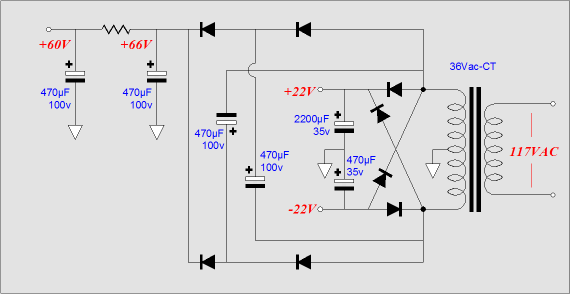
The OpAmp provides a gain of 100 (+40dB) and employs a quasi 2122Hz-based low-pass filter function in its feedback arrangement, as the 0.0075µF capacitor across the 10k feedback resistor increases the amount of feedback for frequencies above 2122Hz, thereby decreasing the output for these higher frequencies. Quasi low-pass filter? Because the OpAmp is configured in the non-inverting topology, the capacitor-shunted feedback resistor defines a shelving network. Once the output frequency hits 212,200Hz, the attenuation stops and the shelving floor of unity gain is reached. The grounded-grid amplifier employs an Aikido touch, as the leftmost triode’s grid sees a small sampling of the B+ noise, so that noise is cancelled at its plate. The grounded-grid amplifier’s output feeds a 50Hz-500Hz shelving network that finishes the RIAA equalization. And the cathode follower buffers the shelving network fro the output, while providing a low-impedance output. All in all, an interesting design, but what can make it more interesting still is to apply a few tricks to the power supply. The following power supply schematic is familiar to TCJers, as it has appeared a few times before, mostly in articles about hybrid tube/MOSFET power amplifiers.
The single center-tapped secondary can power the entire preamp. The +/-22Vdc rails will feed positive and negative 15V voltage regulators, which in turn will feed the OpAmp and the tube heater string. (The positive voltage regulator can power two 6DJ8 heaters in series with 6.8-ohm 2W power resistor, which will protect the heaters from current inrushes and drop the 15V down to 12.6V. Why the positive regulator? Just about every OpAmp presents an unequal PSRR figure, with the negative power supply connection delivering a worse PSRR, so it is better to burden a positive regulator.) The +60Vdc B+ rail is created by the voltage tripler made up of the four extra rectifiers and power supply capacitors. (Yes, before you ask, the tripler circuit can be replaced by a quadrupler or pentalupler circuit, as they just require more rectifiers and capacitors.) //JRB
|
|


| www.tubecad.com Copyright © 1999-2007 GlassWare All Rights Reserved |