Last time, I mentioned that I didn't believe that the CD was quite dead yet; well, I am not alone. The following is the introduction to a news story from France:
ARLES, France (AFP) - "We hear everywhere that the CD is disappearing, but the disc is not dead," insists 83-year-old Bernard Coutaz, the founder of Harmonia Mundi. "In the classical music field, CD sales still account for nearly 95 percent of the market."
He worries that "catastrophic predictions" are reducing the number of disc sellers when there in fact there "exist customers inclined to buy CDs as long as they can see and touch them."
Sales of CDs have nonetheless plummeted in the last five years, victims of rampant online music piracy and—to a lesser extent—a trend toward digital music sales from online stores.
But classical music in general appears to be resisting the overall CD slide, thanks largely to sales of attractively priced box sets.
Sales of classical CDs increased for the second year in a row in 2006, up 13.3 percent in value...
Read the the whole article at http://news.sawf.org/Tech/32886.aspx
I can see the CD lingering on, if for no other reason, because we do not trust the hard drives in our MP3 players and computers to safeguard our music collections. And if nothing else, the CD makes an excellent backup copy. By the way, if any of you TCJers owns Harmonia Mundi CDs that you no longer need or want, I am interested in helping get rid of them, as I have nothing but admiration and respect for the label and its musical offerings ;)
The last blog held two schematics with typos in them, as were spotted by TCJer Robert McLean's keen eyes. I have since corrected the typos.
Using a low noise FET
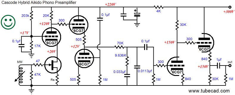
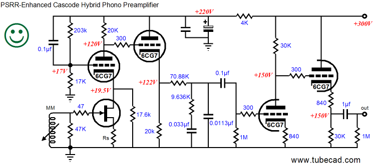
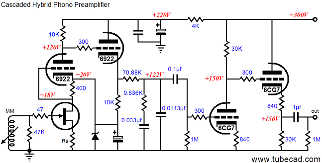
to help the poor tube along in the noise and gain department is an old trick. Unfortunately, it is seldom done right. For example, below is a hybrid cascode phono stage that uses a FET input device and 6CG7s throughout the rest of the circuit.
Wrong? What's wrong with the design?
Well, before looking into its failures, let's first review its theory of operation. The FET’s grid attaches to the phono cartridge and the FET summons nearly all of its transconductance in reacting to the meager voltage proffered by the cartridge, as the triode’s cathode that sits above it locks FET’s drain voltage tight in place. Any variations in the FET's current conduction are then relayed through the plate resistor at the top, developing a voltage gain roughly equal to the FET’s transconductance against the plate resistor. (The unbypassed source resistor will mitigate some of the FET’s transconductance.) Next, the cathode follower accepts its input signal from the cascode’s output, shielding the cascode from the frequency-dependent load presented by the inverse RIAA equalization network and offering that network a low-impedance signal source. The cathode follower additionally serves to nullify the current variations through the cascode input stage, as the cathode follower’s cathode resistor equals the cascode’s plate resistor in value; and since the cathode follower works in anti-current phase to the cascode, any increase in current conduction by the cascode is met with an equal opposite-going current conduction from the cathode follower. This arrangement means that the combination of cascode and cathode follower stage will draw a near constant-current from their common B+ connection, greatly relieving the power supply shunting capacitors from having to squelch any signal-induced noise at the B+ connection.
With all its low-noise gain, what’s not to like about this circuit? We assume high gain and low noise, but does the circuit actually deliver both? The answer is that the circuit provides lots of gain, but lots of noise as well. To better understand where the noise comes from, look at the schematics below.
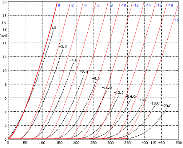
The FET’s drain impedance is so high that the FET effectively constitutes a constant-current source, as can be seen in a typical set of FET drain-current-against-grid-voltage curves.
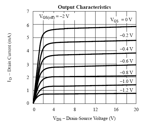
Note that once you move right of the “triode region,” (above about 3V for this FET) there’s not a lot of slope, which means high, high impedance. (Just from eyeballing the 0V-gate plot, the steepest plotline, I see about 80k worth of slope.) This high impedance is then further multiplied by the mu of the triode (actually, mu + 1), so that the voltage divider created by the plate resistor and all that attaches below it does very little dividing; thus, almost all the power supply noise appears at the triode’s plate.
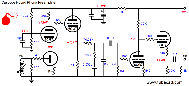
So, is there a workaround? Sure, there’s always a workaround, if you can dream up one that is ;) We can always fall back on the old standard for low noise, the Aikido topology, as shown below.
Note that the Aikido cathode follower receives all of the power-supply noise at its bottom triode’s grid, the result of the cascode offering a close-to-nonexistent PSRR. (Actually, 100% of the power-supply noise might still fall a tad short of completely nulling the noise at the cathode follower’s output, so some tweaking of the cathode follower’s cathode resistor values might be needed to make a complete rejection of the power-supply noise.)
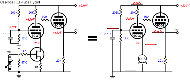
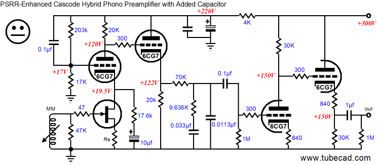
Another approach is to rearrange the cascode, as shown above, so that it can reject the power-supply noise on its own. The first step is to shunt the triode’s grid to the B+ connection, not ground, thereby injecting all the power-supply noise into the grid. The second step is to give the triode’s cathode something to bite on. Imagine the FET/constant-current source were absent; then imagine a cathode resistor equal to the plate resistor for the triode, which would create a split-load phase splitter, with the power-supply noise as an input signal. Thus, as the split-load phase splitter provides no gain, the power-supply noise will be inverted in phase and superimposed on the plate. But as the plate already sees all the power-supply noise, the two opposing signals cancel, leaving no noise at the plate. Well, in general this is true, but as spilt-load phase splitter suffers a slight gain loss, the complete cancellation fall a tad short. The workaround is to specify a slightly larger plate resistor value. How much larger? Just large enough to yield a unity-gain output signal. All we have to do is take the simple formula for gain from a grounded-cathode amplifier and solve for Rk.
1 = muRa / (rp + [mu +1]Rk)
thus,
Rk = (muRa – rp) / (mu + 1).
With a cathode-to-plate voltage of 100V and 5mA of current conduction, the 6SN7’s rp equals 9k and its mu is close to 21. these values gives us a cathode resistor equal to 18.7k, not the 17.6k shown above. Why the difference? The 17.6K value was derived from SPICE simulations, which were based on a 6SN7 SPICE model that is not as accurate as my True Curves™ math model, which was used to calculate the rp and mu.
Duncan SPICE model vs Sofia tube curve tracer plots
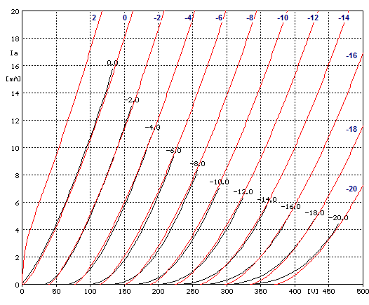
True Curves™ model vs Sofia tube curve tracer plots
Nonetheless, the best practice is to use a potentiometer (wired as a variable resistor) and find the exact value for the triodes actually being used and once the deepest null has been found, replace the potentiometer with a fixed resistor that matches the potentiometer’s value at the null.
Note that this added resistor will appropriate some current from the FET. (If you are brave, you can place a large-valued capacitor in series with the added cathode resistor, preventing a theft of DC current. I, however, am not that brave, as the thought of using an electrolytic capacitor in that position just creeps me out; of course, few high-end manufacturers are likely to feel as squeamish.)
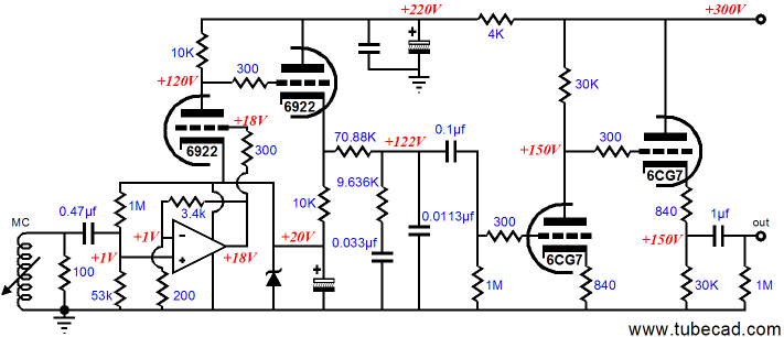
Or, another approach might be to avoid the cascode topology altogether. The phono preamp, shown below, uses a cascading FET-to-tube approach, cascode appearances to the contrary.
The FET input stage works into the 400-ohm drain resistor, not the 10k plate resistor. Thus, the FET achieves much less gain, but the gain it does develop is then amplified by the triode that sits above it, as it its grid DC couples to the FET grounded-source amplifier’s output.
Since I have covered this topology before, I will not go into any further details. In fact, view the above schematic as just a stepping stone to the circuit below.
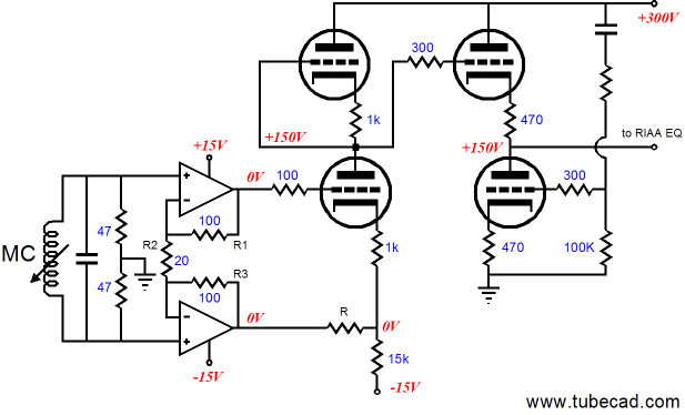
Interesting, don’t you think? We are using an OpAmp without having to provide +/-15V rails. The triode draws 10mA, while the OpAmp draws at least 5mA, and the zener draws a tad less than 15mA. Note the input coupling capacitor and the two-resistor voltage divider, which both serve to establish a +1V DC input reference voltage for the OpAmp. Also note that the 200-ohm feedback terminating resistor does not see the typical large-valued capacitor between it and ground, as we want to amplify the input DC offset up to +18V DC, so as to bias the triode correctly.
Okay, I admit that some head scratching is required. Just why does the 6922-based cathode follower’s cathode resistor terminate into the zener and not ground, for example? Once again, the plate and cathode resistor match, thus ensuring a constant-current draw from the pair, although each stage works in anti-current-phase to the other. In other words, the zener will see a more stable current draw through it this way, which will greatly unburden both it and its bypass capacitor.
So, how much gain do we get from this configuration? The OpAmp’s two feedback resistors set its gain to 18 (+25dB) and the 6922 should develop a gain of at least 20 (+26dB), which against the OpAmp’s gain of 18 equals a gain of 360 (+51dB, as 25 dB + 26dB = 51dB), which also equals this phono preamp’s final gain, as the passive RIAA equalization network loses 20dB, but the 6CG7-based second stage recovers +20dB of gain. Not enough? Then up the zener’s break voltage to 30V and set the OpAmp’s gain to 28. Or, if even more gain is required, then keep the 20V zener and place a diode in series with the feedback resistor that goes to ground, which will allow using a much smaller-valued resistor, thereby greatly increasing the gain from the OpAmp. (Of course, if you are willing to forgo the the advantages derived from DC coupling, then a coupling capacitor can be used between FET and tube stages, which would allow more latidude in obtaining gain from the OpAmp.) Still, +25dB is what many MC step-up transformers deliver and the the output stage could use a higher-mu triode, such as the 6N1P or 6072.
Somehow I have done it again. I have only covered a third of what I wanted and expected to do this time out. Since I am already over my 1,000-word limit, I'll stop here. But I will leave you with a circuit from the next blog entry:
And if you need them, buy some tubes from the GlassWare Yahoo Store.