| John Broskie's Guide to Tube Circuit Analysis & Design |
|
10 October 2007 I have mentioned before that I believe that MP3 album downloads are far too expensive. (And while I am at it, the iPod music store’s download pricing of movies [$10] and old TV shows [$2] is insanely expensive, given the easy availability of Netflix, the public library and, egads, live brodcasts. And, yes, I know the high-pricing blame falls on the studio’s heads, not Apple’s.) Well, here is some good news: Amazon is now selling DRM-free MP3 downloads at a small step closer to reasonable prices. The Amazon MP3 store is in beta and it is not particularly easy to navigate nor attractive, but it is a good, but small, step towards rational download pricing. For further reading, PCMag.com has a good review of the Amazon MP2 web store. What didn’t I like about the new Amazon MP3 store? The downloads are in 256k variable-bitrate MP3 format, wherein a 6-minute track will take up about 9MB, whereas a lossless format would come in closer to 30MB. In other words, the MP3 is not audiophile grade, although it does sound good enough to most people, particularly on an iPod. Second, you must download and install a software applet to download the MP3 files. While I had no qualms, I can see many others stopping right at this point and looking elsewhere. Additionally, the Amazon store is a tad fraudulent in their descriptions. Here’s an example: I found on the Amazon’s download list Edison Denisov, an interesting contemporary Russian composer who writes beautiful melodic and tonal modern classical music.
Unless you live in major world city, however, you not likely to ever see in a music store a CD of Denisov’s music. But through Amazon, you can ostensibly buy an album (on the excellent BIS label) for $0.99! I was delirious with joy. I imagined myself buying 20 like albums for the same price as one BIS CD ($19.98); undoubtedly, a few albums would disappoint, but also undoubtedly a few would satisfy my hunger for interesting new music. I could easily see liking at few albums so much that I did end up buying the CDs. Here is the problem: the downloadable album doesn’t actually cost $0.99. Rather, that was just the price for one track—the one and only track that was available from the album. Clicking on the "Buy MP3 Album" shown below, as I did, instantly buys not the album, but the track.
Here is an other example, the great album Hoodoo Man Blues, by Junior Wells and Buddy Guy sells for $7.92...except that it doesn’t. Your $7.92 only buys you 8 of the album’s 14 tracks. Okay, let’s pretend that Amazon cherry-picked the only good tracks on the album, but what can one think of their strategy of doing the same to classical compositions? For example, the second and third movements are downloadable of Brahms Violin Concerto Op. 77 with Julia Fisher. The only way to get the first movement is to buy the CD. Absolute, unadulterated and unambiguous idiocy. Maybe Amazon should try selling novels without the first chapter. So why bother with the Amazon MP3 web-store? If your musical taste runs more in the mainstream, towards Pink Floyd, Feist, Kanye West, Radiohead, KT Tunstall…then the store makes more sense, as $7.99 price for a complete album is certainly a move in the right direction. Speaking of Radiohead, did you see where they are offering their latest album on a pay-what-you-think-it-is-worth basis. God bless them. Considering that they are a hot, much-in-demand band, their move is all the more bold. One day soon, I hope to be able to buy downloadable, DRM-free, lossless albums for a few dollars each.
Interesting OTL Design from MJ Now, I have covered the topic of OTL drive balance many times before. Yet few seem to have paid much attention, as I continue to receive many schematics via e-mail that display intrinsically unbalanced circuits, which is an odd thing to find in any push-pull amplifier, as the push-pull amplifier relies on balanced operation to achieve both greater output power and lower distortion.
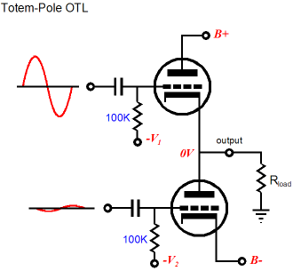
So let’s quickly review the totem-pole output stage. One tube stands atop another tube, with the load attaching at the connection in between tubes; each tube must share an equal burden in driving the load; and the top tube’s cathode follows it grid, while the bottom tube’s cathode is “grounded” to either ground or a negative power supply rail. And here is where the imbalance is created, as the top and bottom tubes cannot see the same amplitude of drive voltage (as referenced to ground.) Why? Because the top tube’s cathode is following its grid, so only a fraction of the drive voltage will emerge above the cathode voltage swing; and the since the bottom tube’s cathode is grounded, its grid will see all of the drive voltage. In other words, the top tube sees effectively much less drive voltage than the bottom tube and drive voltage against transconductance equals current swing, so the bottom tube will be wildly swinging current, while the top tube lazily swings a small portion of the current. Imagine steering a bicycle with crazy handle bars: one two feet long, the other only half a foot.
Could you steer this bike by applying equal arm movements to the right and left hand grips? No, not possible. Now let’s look at some of the lame OTL designs that end up in my mailbox.
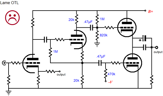
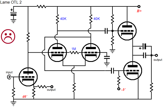
In the above schematic, we see a grounded-cathode amplifier cascading into a split-load phase splitter, which in turn drives the totem-pole output stage. Since the phase splitter’s plate and cathode resistors share the same value, the signal from each output will equal in amplitude, but differ in phase. Thus, the output stage will see imbalanced drive signals. The next schematic looks a bit more complex, but the key feature is the long-tail phase splitter’s equal-valued plate resistors. Once again, the output stage will see imbalanced drive signals.
Both circuits hold perfectly good front-ends for a conventional push-pull power amplifier output stage, wherein both cathodes are grounded and both plates attach to the load, wherein an equal amplitude of drive signal is essential. With the totem-pole output stage, however, the bottom tube will always be overdriven and the top tube will be underdriven. This imbalance is intrinsic and no cheap trick (such as fancy coupling capacitors, or extra zeners) is going to fix the inherent imbalance presented by the totem-pole output stage—although a large amount of negative feedback will make for some fairly good measurements, but never the stellar measurements that it could yield with a truly balanced driver and output stage. Before we review the different driving stages that do work, let’s examine the correct ratio of top to bottom drive signals necessary to guarantee equal current swings. 80/20? 70/30? 60/40? The correct answer is that it all depends on the tubes used and the load impedance and the class of operation. If we ignore the triode’s plate resistance and assume class-A operation, the formula is an easy one: Ratio = 2gm•Rl + 1 For example, if the tube’s transconductance equals 50mA/V and the load impedance equals 100 ohms, then the ratio is equal to 11:1; if, however, the load impedance is 10 ohms, then the ratio is equal to 2:1; and 0 ohms, 1:1. In other words, the two lame OTL circuits above will work perfectly with a 0-ohm load, such as a short to ground, which makes perfect sense, as this load impedance ensures that both top and bottom cathodes do not move with the applied input signal. This formula assumes strict, honest-to-God class-A operation, not the cheesy, make-believe "class-A" found in ads in glossy audio magazines.
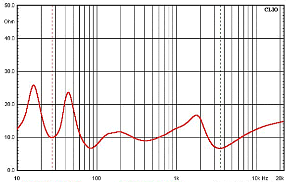
If the lure of low idle current (and, thus, long tube life and low heat) is too strong to resist, then the totem-pole output stage can be run in class-B or a lean class-AB. Which makes the previous formula no longer accurate; the new formula for the drive ratio becomes Ratio = gm•Rl + 1 For example, if the tube’s transconductance once again equals 50mA/V and the load impedance equals 100 ohms, then the ratio is equal to 6:1; a load impedance of 10 ohms, 1.5:1. In a class-B output stage, both top and bottom output tubes are near cutoff, so as soon as one tube increases in conduction, the other cuts off completely, conducting zero current. And as all push-pull amplifiers abide by the simple formula, Iout = Ia – Ib, all the current following through the engaged output device must also equal the current following through the load impedance, as Iout = Ia – 0 is the same as Iout = Ia. On the other hand, in a class-A output stage, both top and bottom output tubes conduct half of the peak output current at idle, so as one tube slowly climbs to maximum conduction, the other slowly backs off conducting until it finally reaches zero current conduction. So, for example, if the top tube conducts an additional 10mA, the bottom tube will conduct 10mA less. To continue this example, let’s assume an idle current of 100mA, so the top tube experiences a conduction of 110mA, while the bottom tube sees its current conduction fall to 90mA. Plugging these number in the Iout = Ia – Ib formula yields 20mA into the load. Since we have our ratio formulas, why not just fix the needed ratio in place and call it a day? Well, that is precisely what many circuit designers do. For example, the split-load phase splitter’s cathode and plate resistor values can mirror the ratio, just as the long-tail phase splitter’s plate resistors can echo the same ratio. So, what is wrong with this approach? Nothing, as long as the load impedance is unvarying, such as a 75-ohm resistor. Loudspeakers and headphones do not mimic resistors when it comes to frequency-independent resistance. In fact, many rollercoaster rides hold less severe up and downs. For example, the plot below is concidered quite flat and easy for an amplifier to drive.
Remember that the word “nominal” is used for a good reason when describing load impedance. Still, I must admit that designing for a target impedance, incorporating a fixed drive ratio, and then applying a healthy dose of feedback will prove fairly effective.
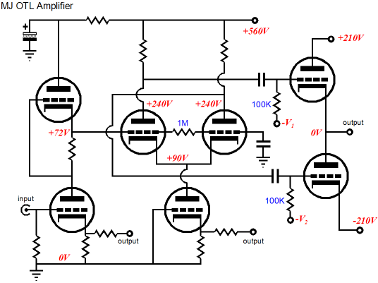
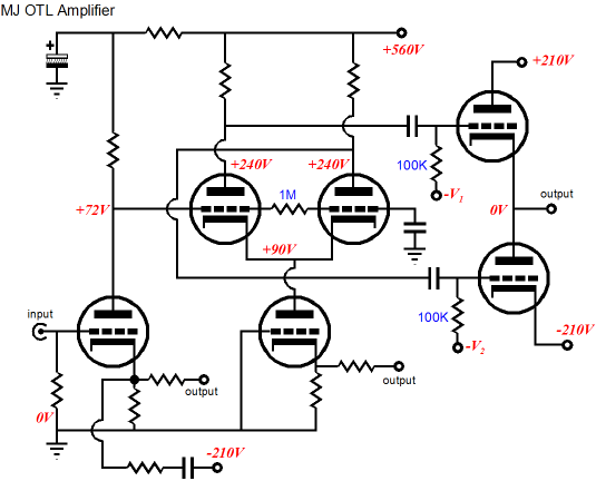
MJ OTL Amplifier
After that long introduction, let’s look at the MJ OTL amplifier circuit. First of all, the above schematic is greatly simplified to better reveal the hidden topology. The long-tail phase splitter makes use of an active cathode load. I know that this feature will get labeled constant-current source, but it is not even close to being a constant-current source; it presents the same impedance to the cathode that a fixed resistor would that would pass the same amount of current with same voltage drop across it, whereas a closer approximation to a true constant-current source would present a huge impedance, say at least 10Meg, no matter what the voltage potential.
Let's quickly review how the long-tail phase splitter works. The leftmost triode receives the input signal, which gets halved at its cathode, so effectively both triodes see half of the input signal, from their grids to their cathodes. Thus, the leftmost triode works as a grounded-cathode amplifier, while the rightmost triode works as a grounded-grid amplifier. The result is roughly the same output signal, but in anti-phase, as the grounded-cathode amplifier inverts its input signal, whereas the grounded-grid amplifier preserves the input phase. The higher the impedance of the shared cathode load, the better the balance at the outputs. Now, closely look at the extra resistor that connects to the output. This connection feeds a portion of the output voltage swing to the cathode of the active load, which then is amplified, in phase, at the long-tail phase splitter’s plate resistors. Effectively, the long-tail phase splitter has been transformed into a cascode amplifier, whose bottom stage defines a grounded-grid amplifier.
Why? This arrangement forces the output stage into balanced operation, as it equalizes the drive signals for the top and bottom tubes, no matter what the load impedance. Cool, very cool, but how does it work?
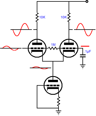
The aim is to superimpose 50% of the output voltage swing on the drive signals present on the long-tail phase splitter’s plates. This added signal will add to the left triode’s output, while it will subtract from the right triode’s output. For example, given that the output stage’s output into a load is 8Vpk and that the top output triode sees 10Vpk drive signal and the bottom triode sees a 2Vpk drive signal at its grid, the long-tail phase splitter’s output signal amplitude, without the correction signal, would have to be 6Vpk from the both left and right phase splitter outputs. The correction signal establishes, in this example, a drive ratio of 5:1. A different load impedance, a different drive ratio; but no matter which ratio is established, both triodes will see identical peak cathode-to-grid voltage swings. Now here is an interesting question: What happens when an external 1Vpk pulse is applied to the amplifier’s output?
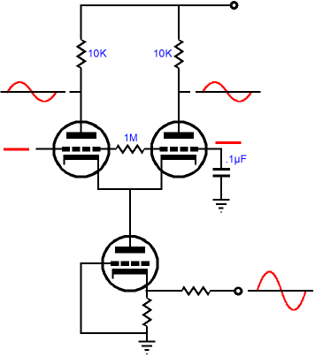
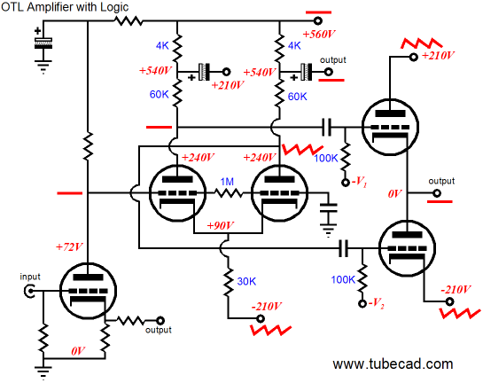
Half of the 1V pulse will appear at both of the phase splitter’s outputs, in phase. But as the top triode’s cathode has been forced 1V positive, the +0.5V pulse presented to its grid is effectively a negative going 0.5V pulse, which will diminish the top triode’s current conduction by 0.5 against its transconductance, thus bucking the external pulse. The bottom triode’s cathode is fixed, so it sees a +0.5V pulse at its grid, which will augment its current conduction by 0.5 against its transconductance, thus bucking the external pulse. In other words, in a class-A amplifier, both top and bottom triode work equally to fight the extraneous disturbance at the amplifier output. Since the load sees the delta in conduction between top and bottom triodes, the 1Vpk pulse will have to absorb a peak flow of current equal to the triode’s transconductance, which gives the output stage an intrinsic output impedance equal to 1/gm. Attaching the global feedback loop will further reduce the output impedance by the ratio between open-loop gain over closed-loop gain. Okay, I know a few readers are heading for the aspirin bottle now, but you can see how this technique is a valuable asset in designing OTL power amplifiers. The next question is How else can the long-tail phase splitter be corrected to provide a balanced drive for the totem-pole output stage? The schematic below shows how the same 50% output signal injection scheme can be accomplished without an extra triode.
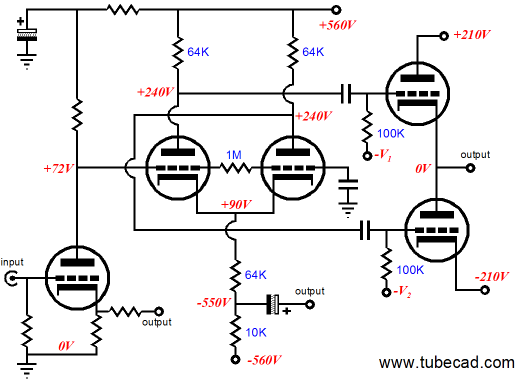
The idea here is that rather than run the long-tail phase splitter as a cascode, we can drive it directly as a grounded-grid amplifier, with a gain of ½. To see how this is possible, imagine both phase splitter triodes wired in parallel, as well as the two 64k plate resistors. Now, we have a grounded-grid amplifier with a plate resistor equal to 32k and a cathode resistor equal to 64k. This gives us a gain of close to 0.5, as both plate and cathode resistors share the same current path. And since the cathode is locked, the current variation that travels through the 64k must create half the voltage swing across the 32k resistor. Using two triodes and two plate resistors does not alter the current ratio relationships. Finding the exact cathode resistor value requires some simple math. where Ra is the value of the paralleled plate resistors. Solving for Rk, Getting the negative 560V power supply rail is easy, with a center-tapped power transformer. But some will not welcome the extra parts and work, so the following schematic is for them.
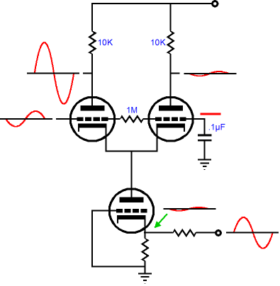
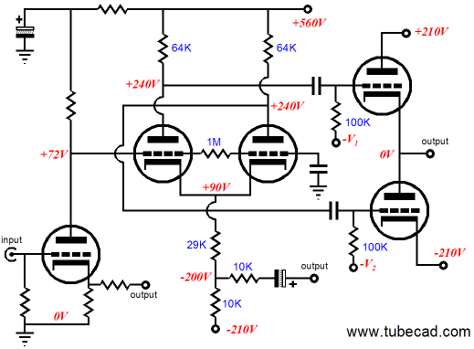
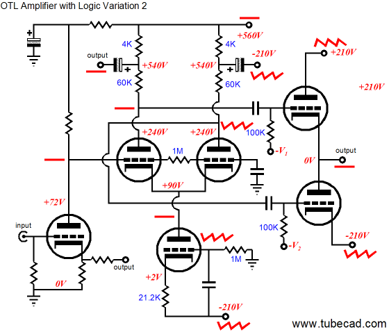
This time the existing -210V power supply rail is used and the added 10k resistor creates a two-resistor voltage divider that presents half of the amplifier’s output voltage swing to the 29k cathode resistor, which in turn generates a gain of 1 at the plates. (Actually, there is bit more going on here and it requires a bit more complex math to set it all straight, but for government work and typical audiophile practice, it is plenty close enough. Remember, many build lame OTL amplifiers with zero understanding of intrinsic balance; some even receive Stereophile class-A awards for their lame efforts.)
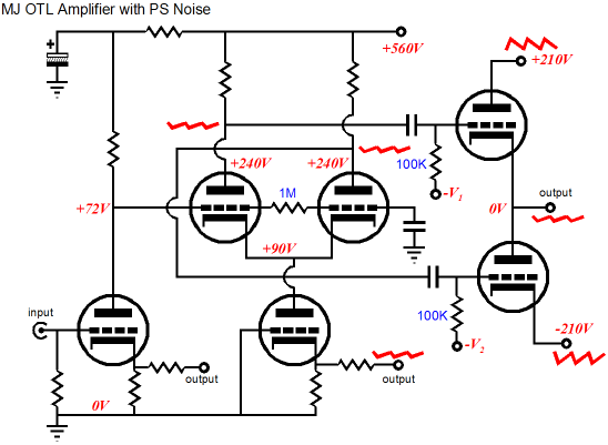
Now the Bad News Reality will disappoint. Let’s be generous and assume that the 560V rail is perfectly free of noise; unfortunately, we cannot pretend that the 210V bipolar rails will be noise-free, as the astronomically high peak output current swings prohibit the usual tube-circuit passive RC filtering via a large-valued series resistor and shunting capacitor. No, the output stage requires a power supply not that dissimilar from that found in a solid-state power amplifier, which makes sense, as both must deliver the peak output current swings into the same 8-ohm load. But where a 30W solid-state amplifier can make do with +/-30V bipolar rails, the tube-based OTL output stage must demand +/-210V rails to deliver the same 3A peak current swings. Yes, seven times more voltage for the tube amplifier, which means at least seven times more internal winding resistance from the power transformer’s primary, and at least seven times more ripple, as no tube-based OTL amplifier chassis is large enough to house two 40,000µF power supply filtering capacitors rated at 250V; instead, we would be lucky to fit two 250V, 1,000µF power supply filtering capacitors.
Yes, inductors would help, but high-inductance implies high DCR and massive cores. Active regulation would also help, but then the raw power supply rail voltage would have to include the regulator’s drop-out voltage margin and the wall voltage’s potential sag, which could easily bring the rail voltages up to 250V, which would require 300V power supply filtering capacitors… Even if we used 280 D-cell batteries to create the +/-210V rails, which we would assume to be ripple free, the effective series resistance of the all those batteries in series would create sagging and swelling power-supply rails, because of the heavy output current into the speaker. This reflection of the output signal on the negative rail is just like the ripple, in that it will be mixed with the drive signal, as the bottom cathode fall out of step with its drive signal.
OTL Logic
Mr. Kadou Teppei tried to add some magic by injecting some of the -210V rail noise into the input stage, where the noise would be present in phase to the bottom triode and inverted to the top triode, helping, but not totally eliminating the noise from the output, as the top triode needs only a small fraction of anti-noise signal that the bottom triode needs.
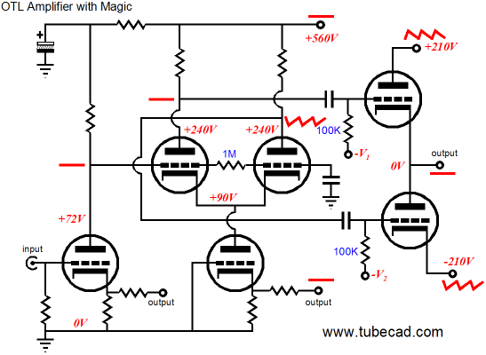
So, let’s dispense with magic and half measures and try logic and cunning instead.
Or, going with the constant-current source cathode load:
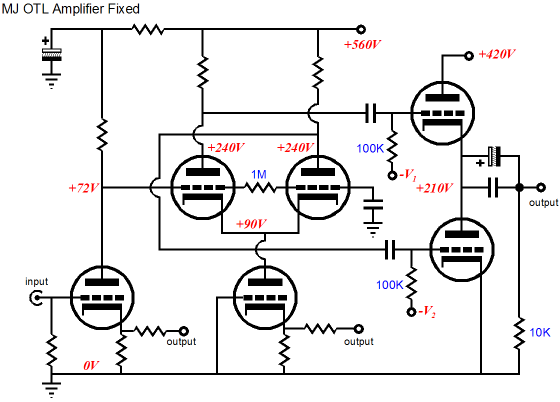
In both of the above examples, the output signal is fed back unattenuated into the phase splitter, thus ensuring balanced drive. Additionally, the output stage’s power supply rail noise is accounted for, making the output noise-free. I will not go into greater detail on how these miracles are brought about, as I have covered this all before (download this PDF for more details). So is the OTL circuit from MJ a complete bust? No, not at all. In fact, if we are willing to live with coupling capacitors on the output, we can redeem the whole enterprise, as the major source of noise will have magically disappeared.
The above schematic is missing a few capacitors, but the general topology is sound. So, is it better than the two previous circuits? Each of the three circuits holds its own pluses and minuses; the best path is to discover what features and liabilities each topology holds and decide which fits with your own system or resources or inclinations. This turned out to be a much longer post than I expected. And, as always, much, much more could be added. For example, how about an Aikido long-tail phase splitter? Next time I’ll show you how it’s done.
//JRB
|
Support the Tube CAD Journal TCJ Push-Pull Calculator
TCJ PPC Version 2 Improvements Rebuilt simulation engine *User definable
Download or CD ROM For more information, please visit our Web site : To purchase, please visit our Yahoo Store:
|
|||


| www.tubecad.com Copyright © 1999-2007 GlassWare All Rights Reserved |