| John Broskie's Guide to Tube Circuit Analysis & Design |
|
17 December 2007
The Brook Amplifier: An Amplifier
with Automatic Bias Control (Why OCR? First, I want the search engines to be able to find it. PDFs filled with images of scanned pages of text are the dark matter of the web; they are there, but you don't know it and cannot find it. [Dark matter? Astrophysicists tell us that dark matter is of unknown composition and that it is dark, neither emitting nor reflecting observable electromagnetic radiation. Yet its existence is implied by its gravitational effects on non-dark matter.] Second, I want the article to print more cleanly, as my 51-year-old eyes do not need any more strain; and this article deserves the paper tribute.) Sixty years ago, this interesting and fun-to-read article appeared in Audio Engineering magazine (the precursor of Audio magazine). Written by J. R. Edinger, of Brook Electronics, the article lucidly explains how the push-pull Brook amplifier uses a dynamically shifting bias voltage to create an output-mode-shifting amplifier. Simply put, the Brook amplifier offers two faces: a push-pull, class-A, when at idle or under low signal levels, low-distortion, low-power amplifier; and a lean, mean class-AB, higher-distortion, but high-power amplifier when provoked by large input signals. Now, this is the right sort of split personality; it’s much like having a fun, obedient, and loving dog who will turn into a fearless, frothing, flesh-tearing guard dog only when a loathsome intruder creeps into your house late at night.
How does the Brook amplifier work?
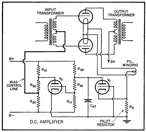
But as the amplifier is asked to go beyond its class-A range, the cathode sees a greater current conduction, which in turn creates a greater positive voltage drop, which in turn gets amplified by the DC amplifier, but in an inverting mode, so the DC amplifier’s output will swing negatively, when faced with a positive input signal. The phase inversion comes from the second stage within the DC amplifier, which constitutes a grounded-cathode amplifier. The DC amplifier’s output is DC coupled to the center-tap of the interstage transformer, which will relay the downward drift in bias voltage to the output tubes. As the Brook amplifier’s output tubes see a greater negative bias voltage at their grids, their idle current drops, which moves the output stage out of class-A operation into class-AB, then class-B mode, if the input signal is large enough. Wait a minute, if the output stage's greater conduction causes a more negative bias voltage at the output tubes' grids, how do the output tubes conduct more, if they are being turned off? The DC amplifier has an internal capacitor (C27, 0.1µF) that slows the amplifier’s reaction to input signals, limiting the amplifier frequency response to only those frequencies below around 6Hz, the time constant that results from the capacitor being charged through resistor R28. (In fact, a second low-pass filter is located at the DC amplifier’s output, which has an even lower transition frequency.) In other words, the DC amplifier ignores the actual music signal and only amplifies the shifting music envelope of increased current draw. The next question to answer is how the shift away from class-A increases the potential power output. The answer is intriguing, but it must wait for a preparatory side trip to single-ended amplifiers with shifting bias points.
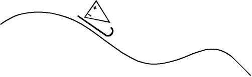
Back on the Sled Now if I had just read that last sentence, I would stop reading and ponder on my own why push-pull amplifiers require a completely different approach to shifting bias than single-ended amplifiers. Two output tubes versus one? No DC current versus a sustained magnetizing DC current through the output transformer? A balanced driver stage versus unbalanced driver stage? Or...? As is so often the case with multiple choice questions, the correct answer is "none of the above." The Brook amplifier goal is optimal music playback, not increased efficiency or extended output tube life. The amplifier runs in a relatively heavy-current class-A mode at idle, to produce the cleanest output signal. The rich idle current moves the 2A3/6B4G triodes into their most linear range and then enhances that intrinsic linearity by ensuring that both triodes completely overlap each other’s transfer curve, thereby creating a more linear sum. Class-A operation of a push-pull amplifier requires an idle current at least equal to half of the peak output current, whereas class-B operation requires an idle current as close to complete cutoff as possible. In the Brook amplifier, the class-A output is 5W (peak) and the class-AB output is 30W (peak). As long as the power output is below 2.5 watts (peak), the automatic-bias-circuit (A.B.C.) does not alter the negative bias voltage presented to the output tubes. Once the output exceeds its class-A limit, the A.B.C. kicks in, reducing the negative bias voltage, allowing the amplifier to gracefully slide into class-B mode.
True class-A is truly beautiful and, like so many beautiful things, expensive. Class-A is costly in terms of efficiency, tube longevity, and maximum power output. Since the Brook amplifier aims at delivering a near-perfect reproduction of musical events, the limited output power would steal from its achievement.
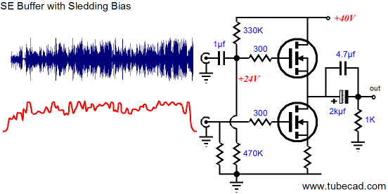
With the sledding-bias arrangement for a single-ended amplifier, in expectation of a crescendo, we raised the mild trickle of idle current to an intense torrent, allowing the amplifier to deliver more output voltage and current into the load. The Brook amplifier, in contrast, lowers the bias voltage (a bit after and during the crescendo), and with it, the idle current to achieve the same end: more power. Why the opposite approach? The single-ended amplifier, shown above, is primarily current-limited, as is the Brook class-A push-pull amplifier, but in an entirely different way.
The Essential and the Accidental The sledding-biased amplifier's goal was a single-ended amplifier that was primarily efficient, producing no more heat than was absolutely required. The goal might have been altogether different, as we might have accepted an excessively high idle current, say 10A for a nominally 16W amplifier, which need only idle at 2A to achieve it 16 watts of output power. If the goal were absolutely the most linearity at any cost, then 10A would certainly be a move in the right direction. Such an amplifier is primarily voltage-limited (assuming a 40V B+ voltage). Increasing the idle current to 20A would not increase the power output by a milliwatt, nor would halving the idle current to 5A increase the power output. Increasing the B+ voltage, on the other hand, would dramatically increase the potential output power. The low B+ voltage limits the maximum voltage swing into the 8-ohm load. This example has been a solid-state one, but a tube-based example is also possible. In fact, with a triode-based single-ended amplifier, decreasing an excessively high idle current could also increase the maximum output power. How? The zero-grid-to-cathode-voltage boundary corrals the maximum positive-going input signal, which in turn limits the maximum symmetrical negative-going plate-voltage swing. "Wait a minute," you are thinking, "you might be limited by the zero grid voltage stop sign, but my single-ended amplifier isn’t, as it uses an interstage transformer, so grid conduction is no problem." If only it were so. Once the grid becomes forward biased relative to its cathode, it defines a diode with the cathode and current flows from the cathode to the grid, causing the grid’s normally near-infinite impedance to plummet. This nosedive in impedance is also reflected through the interstage transformer to its primary, thereby dragging down the driver stage. The big advantage of using the interstage transformer over using a coupling capacitor is that the transformer’s secondary is made from relatively low DCR wire and it will not store an altered bias voltage, as a capacitor would. (Capacitors preserve voltage; inductors, current. Ideally, no DC current flows through a charged capacitor and no voltage develops across a stressed inductor.) Had a cathode follower been used to directly drive the output tubes' grids, then the grids could be driven easily into conduction, assuming buffed cathode followers had been used.
Too Many Words and Not Enough Pictures
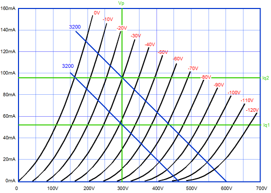
Setting the idle current to Iq2 will lower the distortion, but provide less output; setting to Iq1, more output, but also more distortion. The loadline is the same, but the permissible voltage swing into the loadline differs with the change in idle current.
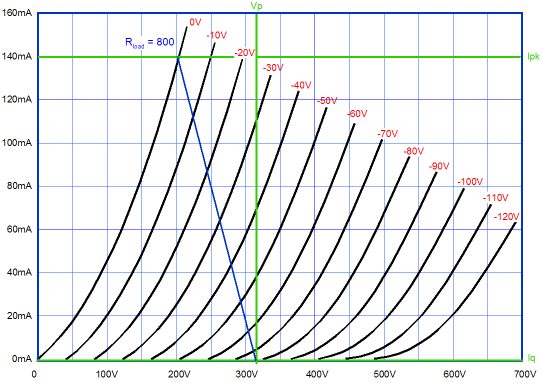
A Few Words About Loadlines In contrast, with a true class-B, push-pull amplifier, its output tubes are completely cut off at idle. This means that the output transformer’s secondary is only engaged when current flows through either output tube and only through the conducting triode’s branch of the secondary winding. Thus, a transformer with a nominal winding ratio of 20:1 will effectively hold a winding ratio of 10:1 with each half of the primary to the secondary. Thus, the transformer will reflect an 8-ohm load as 800 ohms across the output transformer’s primary, as the loadline spans only one output tube plate at a time.
Where defining a loadline gets really tricky is when the amplifier’s mode of operation is class-AB, as each triode will see a varying loadline, whose slope is determined by the status of conduction through both halves of the primary and the output tubes and the degree of magnetic coupling between windings. Because the load line cannot be represented by a straight line, the best method to analyze a transformer-coupled, push-pull output stage is to use a composite set of plate curves.
The composite plate curves are made by subtracting one output tube's current conduction form the other. At idle, when both tubes conduct equally, the two currents equal and thus cancel, which places the center of the composite curves at zero grid volts and zero current into the load. As the output stage is driven by inverted drive signals, the non-linear transfer curves are averaged. So one tube's greater conduction is met with the other tube's lesser conduction, hence the straight lines formed in the composite plate curves drawn from two output tubes operating in pure Class-A and the wobbly curves formed by the same tubes in Class-AB.
Making the Transition First of all, it is interesting to note how, in a quite unintended way, the downward sliding bias method has been implicit to some small degree in all cathode-biased amplifiers and even in many internally capacitor-coupled amplifiers. Interestingly enough, using a conventional cathode-bias arrangement in a single-ended amplifier has the effect of increasing the negative bias during high output, as the “rectification-effect” that results from the triode’s greater ability to increase in conduction rather than be turned off results in an unbalanced current draw through the bypassed cathode resistor, with the positive voltage across the cathode resistor swings being greater than the negative swings, which then increases the voltage charge across the cathode resistor’s bypass capacitor. Depending on the capacitor’s value, the capacitor will slowly discharge, leaving an envelope of lower idle current, which we usually do not want. But in a single-ended amplifier with an overly rich idle current, like the one implicit in the graph above, the lower idle current works to our advantage. How big is the rectification effect? Not that big. With a perfect triode, zero rectification; with a real triode, a little less than the percentage of 2nd harmonic distortion, which makes perfect sense, as 2nd harmonic distortion is very much a measure of the triode’s nonlinear handling of a symmetrical input signal. In the case of fixed-bias, the coupling capacitors can become excessively charged by driving the grid into positively. As long as the increased charge across the coupling capacitor is modest, the amplifier will approximate the Brook amplifier, as its output stage will shift into a lower idle current. The danger, of course, is that the output stage might already be running in a lean class-AB mode and the further downward shift in bias voltage will completely turn off the output tubes. In other words, I believe that we tube-loving folk are lucky that our tube-based amplifiers can often adapt themselves to a crescendo by shifting bias points on the fly. I am convinced that this helps explain why a 25W tube amplifiers sound about twice as powerful as a 25W solid-state amplifiers. I also believe that this explains why 12W class-A, push-pull tube amplifiers sound just as powerful as 25W lean class-AB amplifiers. (I once built up identical push-pull, EL34-based power amplifiers, except that one was triode-connected and the other ran pentodes. Of course, the pentode amplifier won in maximum power output. Nonetheless, triode-connected amplifier sounded more powerful. So I had several friends perform the same sonic evaluation, not knowing how the amplifiers differed. After playing each amplifier for a few tracks, I asked which amplifier sounded more powerful. Both audiophiles and normal people all thought the triode-based amp, the one with less than half the power, sounded more powerful. Interestingly, when I revealed that the seemingly weaker amplifier actually put out more than twice the watts, many listeners, maybe all of them, immediately backpedaled and pointed at the pentode-connected amplifier as sounding more powerful. When I grilled them on their flip-flop, the answer I heard was always the same: but it must sound more powerful, since it puts out more watts. Amazing what docile consumers we have become. By the way, the triode-connected amplifier also ran a much richer idle current.)
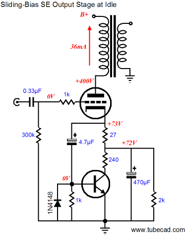
Broskie Sliding-Bias SE Amplifier The following circuit is my answer. Imagine a power triode, say a 300B, and imagine a ridiculously high-valued cathode resistor, say 2k. with 400V on the plate, such an amplifier would draw about 36mA through the output tube. This is at idle and when presented with moderate input signals.
On the other hand, when the amplifier is provoked beyond its class-A envelope, the NPN transistor conducts, pulling down the cathode voltage by shorting the bypass capacitor with the 240-ohm resistor to ground. The cathode voltage falls by about 15V and the idle current more than doubles. If you have carefully designed your single-ended output stage, the potential power output should increase by fourfold. In this topology, however, a bit more could reasonably be expected, as the falling cathode voltage gives the output tube a tad more voltage to work with. If I were not so restrained by shame, I would have labeled this design "Turbo SE™." Fortunately, I am not that shameless. Unfortunately, nor am I greedy enough to patent this scheme, as it works quite well in SPICE simulations and would make the foundation of a desirable amplifier. Imagine a seemingly 2W (RMS) single-ended amplifier whose output tube only dissipated 12W at idle, but could still put out 9W (RMS); or, think big, a 10W (RMS) single-ended amplifier whose output tube only dissipated 60W at idle, but could still put out 45W (RMS). One aspect of this design that should always remembered is that it is a reactive design, not a proactive one. The amplifier responds to being overdriven, it does not anticipate the increased need, as the sledding-bias design does. In addition, the design assumes that interesting music will be played through it. Much like the 50W tweeter that burns out when presented with 10W of constant sinewaves, this design assumes that crescendos are fairly infrequent, not constant. Still, it is a wonderful compromise that would yield long tube life and low heat, yet could deliver some real power into your loudspeakers.
Next Time
//JRB
|
High-quality, double-sided, extra thick, 2-oz traces, plated-through holes, dual sets of resistor pads and pads for two coupling capacitors. Stereo and mono, octal and 9-pin printed circuit boards available.  Aikido PCBs for as little as $20.40 http://glass-ware.stores.yahoo.net/
Only
Download or CD ROM www.glass-ware.com
|
|||


| www.tubecad.com Copyright © 1999-2007 GlassWare All Rights Reserved |