| John Broskie's Guide to Tube Circuit Analysis & Design |
|
26 March 2008 This week's blog entry is dedicated to Steven Key. Thanks.
Circlotron Amplifiers Once Again What could possibly be controversial about tube circuits? With the SRPP circuit it was my pointing out its intrinsic push-pull nature; with the patented Transcendent OTL, its patented zener trick not actually delivering true balanced drive to the output stage; and with the Circlotron amplifier, its plain simplicity and its inability to squeeze class-A blood from class-AB stones. With near-metaphysical anguish, many an SRPP devotee resented my differing perspective on the topology’s fundamental functioning. On the other hand, the most vociferous advocates of the patented Transcendent OTL and Circlotron amplifiers were those that had actually bought a patented Transcendent OTL or Circlotron OTL "Class-A" amplifier and who were greatly displeased with my uncouth disparaging of their expensive equipment; no reasoned arguments, no scope traces, no measurements, just the same How-dare-you... and I-just-spoke-to-the-guy-who sold-me-the-amp-and-he-says... retorts. Of course, most of the opposing-viewpoint e-mails were polite, but argumentative, which I actually greatly appreciate. Remember the two e-mails from Pickacr and the single e-mails from William in England and EJ in Arizona, for example. (To of be frank, I haven’t gotten any truly nasty e-mail in years, which inclines me to believe that either I am losing my touch or that most readers know better than to battle me on my own turf—or that nobody is reading this blog, but then how do I explain the million-plus hits this Website garners each month?) So do I dare disturb the universe again? Of course I dare, as Mr. Eliot put it so nicely:
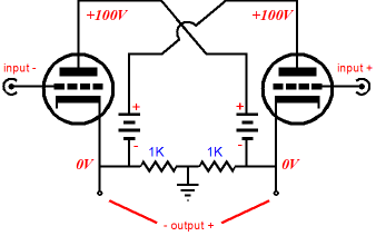
The Magic Behind the Circlotron
If you are new to the Tube CAD Journal, then the following TCJ links will help you understand better how this topology works:
Solid-State Circlotrons
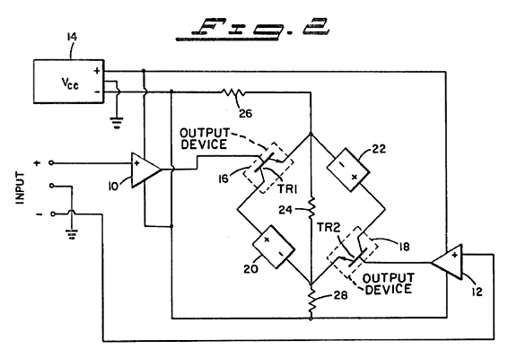
Sad to say, but I do not believe the patent actually describes all that it claims. First of all, I remember reading in the Audio magazine review of the Sumo Nine power amplifier that it must be a class-A amplifier, as the reviewer couldn’t see how the current paths worked. Well, the patent examiner also thought that it must run in class-A, so it must be... There is nothing, however, that forces this Circlotron variation to work only in class-A. Please, stop and think about it for a few seconds, unlike class-B, class-A mode of operation is load dependent; and all class-AB amplifiers are class-A amplifier up to a certain voltage swing in a defined load resistance. For example, if a 10,000-ohm loudspeaker is attached to the cheap department-store power amplifier, the amplifier will put out class-A voltage swings, because the load draws so little current that neither output devices cuts off. On the other hand, given the most powerful class-A amplifier, say one that puts out 200W into 8 ohms, this amplifier ceases to be a class-A when faced with a 1-ohm loudspeaker and more than 25W of output. In other words, how could the topology know what speaker impedance would be attached to it before it was attached? It can’t. In order to make an always-class-A amplifier, the amplifier would have to measure the load resistance and then adjust the idle current to match it.
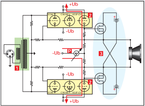
Thorens TEM 3200
The amplifier uses an input transformer to isolate and split the phase; six tubes to provide voltage gain and two N-channel power MOSFETs to deliver high output current; and no coupling capacitors. Stereoplay magazine says that this is the world's best power amplifier. Perhaps it is, but our concern is "How does it work?"
The above schematic was borrowed from the Stereoplay review of the TEM 3200 (my schematics are not that pretty). Of course, this is only an idealized schematic, with many parts missing. Nonetheless, we get a good idea of what is going on in the amplifier. The input transformer provides a balanced input signal for two tube-based amplifiers that drive the solid-state output stage. The tube amplifier probably consists of two grounded-cathode amplifiers in DC cascade, as the two feedback loops require a non-phase-inverting drive signal for the MOSFETs. The cathode follower at the tube amplifier’s output is DC coupled to the second grounded-cathode amplifier's output, probably through a voltage-dropping resistor, which is probably attached to a constant-current source, which in turn attaches to a negative power supply rail. (I am just guessing, but I bet I am right.) Bongiorno’s patent comes into play in setting the idle current through the output stage, as current flowing through the two tube amplifiers is adjusted via the two resistors shown attaching to a variable voltage or current source, and as the MOSFET's gate attaches directly to the cathode follower's cathode. Now, as any long-time reader of the Tube CAD Journal knows, we have looked into hybrid amplifiers, even hybrid Circlotron amplifiers before. Here is a design I created back in 2000:
The point behind the above schematic was safety, not the novelty of combining a MOSFET-based Circlotron output stage to a tube-based front-end. And we have looked into transformer inputs for phase splitting before:
I love the topology of the amplifier shown above, as it holds only two active devices and yet it would deliver excellent performance, as it uses the Circlotron's best feature: the same output devices are used in the output stage. N-channel and P-channel MOSFETs, like NPN and PNP transistors, never exactly match each other. But getting matched devices is easy when the same device is used throughout.
New Tube Circuit
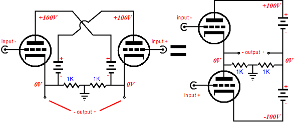
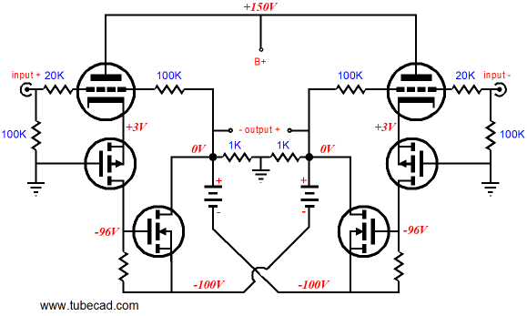
If you didn’t read my Cars, Planes, and Circlotrons article, then the above equation will make little sense, as your eyes will tell you that a Circlotron circuit cannot in any identical to some cheesy totem-pole arrangement of output tubes. What your eye will likely miss is where the ground reference falls in the circuit on the right. Had the signal reference been located at the center of the power supply rails, we would have a Futerman-like output stage, with each output tube require a different magnitude input signal to achieve balanced operation. The same drive issue holds true if we moved the signal reference to the left at the connection between cathode and plate, but with the top tube seeing the smaller signal, rather than the bottom tube. But with the signal reference sitting in middle, both tubes see the same signal magnitude, albeit in anti-phase. Now, with an input transformer, we can use two secondaries, so that each tube (or MOSFET) can receive its own secondary winding. This might work out nicely, but it looks like applying two feedback loops will be challenging, because of the voltage drop across the output devices. Let’s just store this possible avenue for a later date. So is that it? Have we discovered that, indeed, no new tube circuits are possible? What we need is another functionally identical circuit to the Circlotron; fortunately, we can find one in the Tube CAD Journal almost ten years ago.
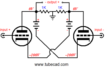
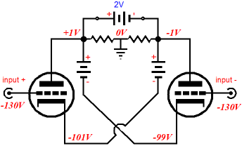
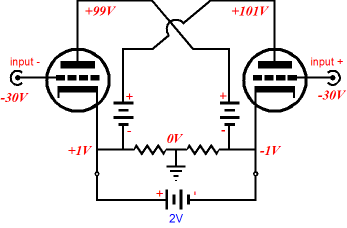
Wait a minute, the Circlotron consists of two cathode followers and the circuit above is made up of two grounded-cathode amplifiers, whose high output impedance is entirely too high for serious OTL use; besides this circuit uses two negative power supplies, whereas everyone knows that the Circlotron uses two positive power supplies. Ready for this, the circuit above uses the exact same cathode-follower-like topology as the classic Circlotron and its distortion, gain, and output impedance are identical to the classic Circlotron. For example, let's look at the output impedance for the above circuit. Imagine placing a 2V battery across the output connections. What would happen? One terminal would be forced negative by one volt, while the other would be forced positive by one volt; one cathode would be forced negative by one volt, while the other would be forced positive by one volt. The grids, on the other hand, would remain fixed. Thus, each triode would see 2V of difference from cathode to plate, with one triode getting 2V extra and the other getting 2V less voltage; and each tube will increase or decrease its conduction by the 1V voltage difference between its grid and cathode. As we can see from the schematic below, the tube on the left will increase its conduction, while the tube on the right will decrease its conduction, both of which will buck the imposed voltage across the output.
Now compare the schematic above with the below. With both circuits, the output impedance formula is the same, Zo = rp/(mu +2).
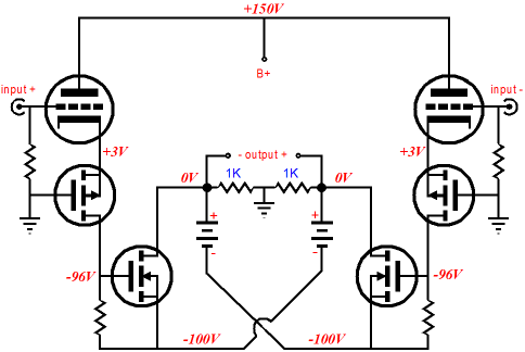
As for this circuit holding two negative power supplies versus the two positive power supplies of the Circlotron, did you ever see that great Three Stooges episode wherein one Stooge tries hammering a backwards-oriented nail into a wall, head against the wall, pointed end facing the hammer? Moe see this and is enraged and yells, “You moron, don’t you realize that nail is meant for the opposite wall?” And he then brings the nail to the opposing wall, so it can be hammered into that wall. Well, it’s sort of like that with power supplies: one man's positive power supply is another man’s negative power supply, as it depends on where you make the ground connection. For example, is a 9V battery a positive or a negative power supply? Or is the question nonsensical? In other words, the exact same pair of power supplies can be used in this circuit as would be used in the conventional Circlotron. A better question might be, What can we do with this inverted Circlotron that we couldn’t do with the established Circlotron? With tubes, nothing strikes me immediately; but if we substitute N-channel MOSFETs for the triodes shown above, we might have something.
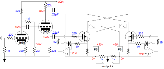
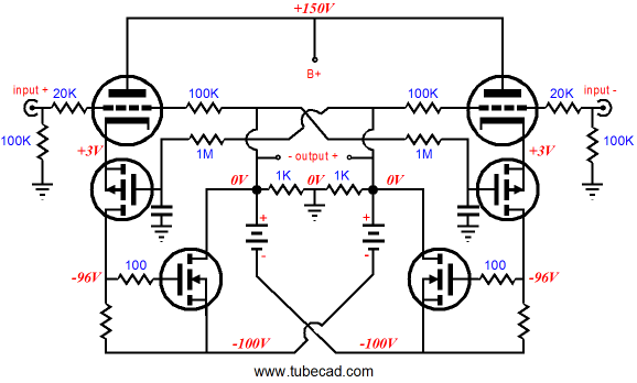
Now we are getting somewhere: no coupling capacitors, a balanced drive and output, but where are the feedback loops? We could either attach a feedback loop to the P-channel MOSFETs’ gates or to the triodes’ grids; the schematic below shows the latter approach.
Why choose this approach? It allows me to add a second set of feedback loops; this time two DC-only feedback loops.
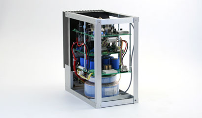
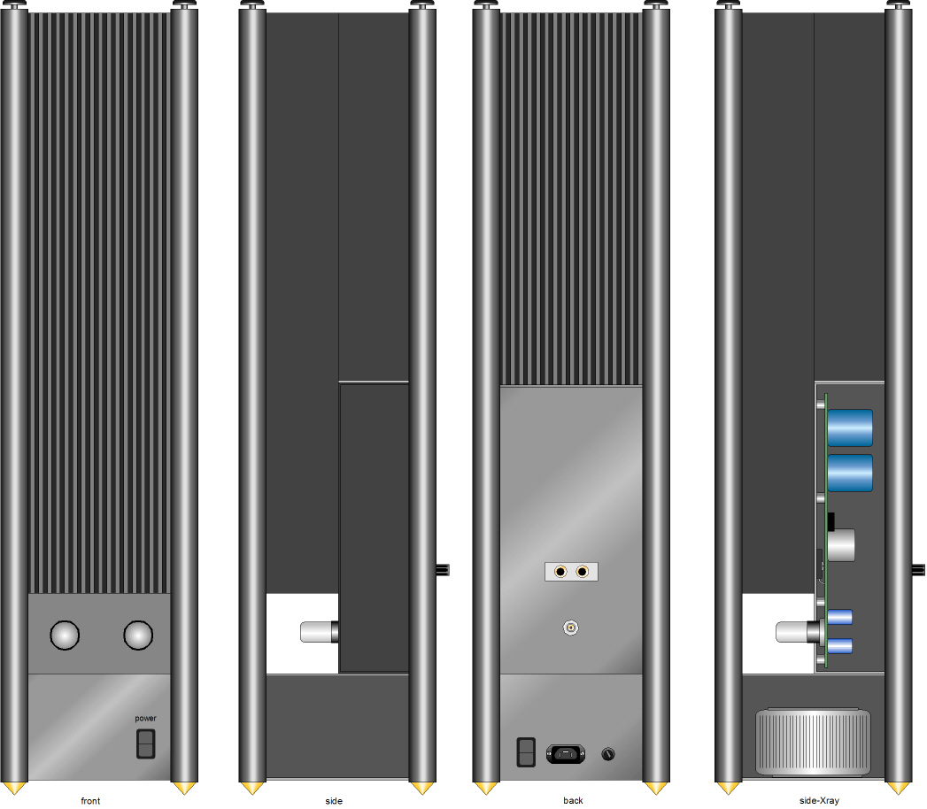
Amplifier Qua Speaker Stands
When I designed this amplifier chassis, I was thinking more along the lines of an SE Moskido power amplifier.
Late-Breaking Headline:
//JRB
|
High-quality, double-sided, extra thick, 2-oz traces, plated-through holes, dual sets of resistor pads and pads for two coupling capacitors. Stereo and mono, octal and 9-pin printed circuit boards available.  Aikido PCBs for as little as $24 http://glass-ware.stores.yahoo.net/
Support the Tube CAD Journal & get an extremely powerful push-pull tube-amplifier simulator for TCJ Push-Pull Calculator
TCJ PPC Version 2 Improvements Rebuilt simulation engine *User definable
Download or CD ROM For more information, please visit our Web site : To purchase, please visit our Yahoo Store:
|
|||


| www.tubecad.com Copyright © 1999-2008 GlassWare All Rights Reserved |