| John Broskie's Guide to Tube Circuit Analysis & Design |
|
25 February 2009
Slightly Newer and Slightly Improved Heat is the enemy of all linear voltage regulators, as a linear regulator must dissipate heat in order to maintain a fixed output voltage and excessive heat will destroy a pass device. It turns out that with all my solid-state regulators, the big limitation is the heatsink, as the LD1085 can pass up to 3A and the IXCY 10M45s CCS can dissipate up to 40W, but the old heatsink was only able to wick away about 5W of heat. (Actually, a second limitation is the 30V maximum voltage differential for the LD1085.) Assuming an excessive 6V voltage differential across the regulator in the heater power supply, the max output current output would be 0.8A for the 5W heatsink; but with the new 8W heatsink, 1.33A; and with a 4V differential, 2A. The same holds true with the high-voltage portion of the PS-1 regulator: with an excessive 100V voltage differential across the 10M45S (30V to 50V would be ideal), the maximum output current output would be 50mA; with the big heatsink, 80mA. With a 50V differential across the 10M45S, 160mA. The H-PS-1, PS-1, and Janus regulators all ship with the new heatsinks. More information at http://glass-ware.stores.yahoo.net
JRB's Dream Tube Tester
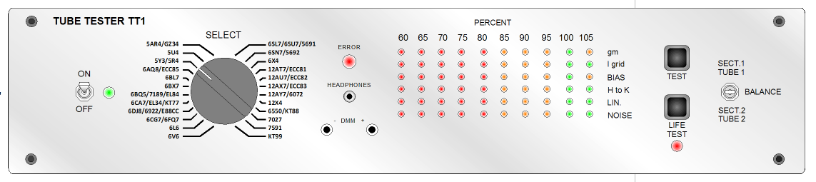
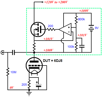
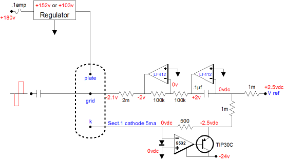
Almost two decades ago, somewhere around 1989-1991, I came up with a novel idea for creating a modern tube tester, one that would test gm, linearity, bias voltage, grid current, heater-to-cathode leakage noise, rectifier conduction, and balance between triode sections or between two output tubes. Why? I owned a Hickok tester, which is truly a thing of beauty, holding its own variac to adjust for line voltage variations and a resistor decade box built into to it for setting up cathode bias tests. Yet I found that my small Sencore TC162 was a much more useful tube tester, although it only tested emission, shorts, and grid leakage. It did, however, include a hugely useful feature: a life expectancy test. (The heater current could be reduced and the emission could be checked; with a new tube, the emission falls only slightly, but with a weak tube, it falls off dramatically.) I believe the Sencore was built in the mid 60's and used a FET somewhere in its circuit. It was not perfect, but it got the job done. For noise testing, I used to use a small test rig that held one high-voltage MOSFET and one OpAmp and a 9-volt battery; it defined a constant current source (with two fixed current settings). With this box I was able to run 6DJ8s under 10mA and 100V or 12AX7s under 1mA at 150V, which allowed me to test the noise and microphonics. (In the schematic below, the portion within green box defines the high-voltage CCS, which I placed in a very small bud box, with a heatsink protruding through the top panel. I actually used an IC voltage reference and toggle switch to choose between two reference voltages.)
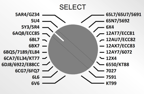
Still it was an ordeal to set everything up and the exposed high-voltage wiring made me fear for my cats' life. When I set about to design my dream tube tester, I enjoyed the advantage of not having any prior schematics to tie me down to the old/right way of doing things. Still, I had tested many tubes and I wanted something safer, faster, and more useful than the typical tester could offer. At the same time, I wanted less. I did not want to test every tube ever made, just those tubes that I used. I knew that I could gain ease of use by forgoing infinite flexibility. In other words, I wanted to just set one switch to the the tube type under test and go. My Hickok, on the other hand, took forever to use because it held so many settings.
The paucity of tube types startles. Where are the 2A3, 300B, 6N1P, 6H30, 12BH7, 5687...? At the time, this list of tubes looked fairly exhaustive. And, to be frank, it still is, as it does cover about 80% of commonly used tubes in hi-fi and music amplifiers. Were I to face the same 24-tube limit today, I would bump the 5U4, 6AQ8, 6BL7, 6X4, 12X4, and 7027 to make room for the above list of missing tubes. Actually, the tester was meant to be able to test tubes like the 6H30 and 6N1P and 12BH7 as it stood, but it would require looking in a table of values for the offsets required. For example, the 6N1P is close to a 6DJ8 in specifications and the same in pin out, so it would plug into the socket designated for the 6DJ8; but the table would tells us that less gm will be realized and different grid-bias voltage should be expected.
But Where's the Mu Test?
Where's the Tube Tester? I have shown the tester's schematic to about twenty EE types, so I haven't been keeping it a secret. I deem it better, however, to show the whole tube-loving world my concept, before my design gets made and patented by someone else (and before I get e-mail asking me to comment on the Supra-Ultra Tube Test-a-Roo...).
$$$$$
How the Tube Tester Works The heart of the circuit was where the tubes plugged in.
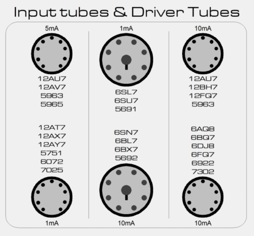
The idea was that the tester would hold many redundant tube sockets, each offering a preset idle current and fixed pin arrangement. So instead of having to look up settings in a chart and having to spin many knobs, we need only insert the tube under test in its labeled socket and the tester would do the rest. Behind the tube sockets, four preset auto-bias current setting circuits: 1mA, 5mA, 10mA for input and driver tubes and 100mA for output tubes. Thus, the redundancy of tube labels. In other words, a 12AU7 can be tested at either 5mA or 10mA. Do not be frightened by the circuit below, although nine out of ten tube gurus might scratch their heads after looking at it. The dotted area represents a tube under test.
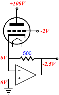
The top two LF412 OpAmps define a DC auto-bias circuit, which works to ensure a steady idle current flow of 5mA into the tube. The way it does this is by adjusting the voltage at the tube's grid until the rightmost LF412's two input pins see the same 0V. The only way this condition can be satisfied is when the bottom 1M resistor sees the same voltage differential as the top 1M resistor sees. In other words, the TIP30's emitter must be at -2.5V. And since the 500-ohm resistor attaches at its other end to the the tube's cathode, which is locked at 0V by the NE5532's near-infinite DC gain, the 500-ohm resistor experiences a current flow of 2.5V/500 ohms, 5mA, as does the tube, as it is directly in series with the 500-ohm resistor. If the tube draws too much current, the TIP30's emitter will swing below -2.5V, which will cause the rightmost LF412's inverting input pin to swing negative, which in turn would cause its output to swing positive, which would then cause the following inverting unity-gain stage to flip the (increasingly) positive voltage (increasingly) negative until the tube's conduction falls to 5mA. The cathode is loaded by a “virtual” ground circuit. This circuit allows the current flowing through the tube to be measured without putting any resistance in series with the plate or the cathode, which would alter the tube’s transconductance (always bringing it lower). The diode across the NE5532's inputs is there to protect the OpAmp, when a bad tube or the wrong tube type is plugged into the tester. The diode limits the inverting input pin from going above about 0.7Vdc.
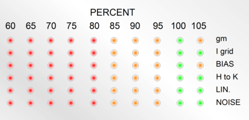
Okay, I know some are scratching their heads at the cathode's connection to the OpAmp's inverting pin. Aren't the inputs to an OpAmp extremely high impedance, on the order of megaohms? How can a tube's gm be tested, if the cathode is loaded by a near-infinite impedance? A good question, but bad assumptions. If nothing else, the 500-ohm resistor attaches to the PNP transistor’s emitter, so near-infinite resistance would be in parallel with about 500 ohms. But is the OpAmp’s fantastic open-loop gain and feedback that brings the 500-ohm resistance down to something closer to milliohms. In other words, the cathode sees a near-zero impedance, a virtual ground of sorts. (What happens if the tube sees an input signal in this arrangement? The cathode remains locked at 0V, but the OpAmp's output swings up and down, as the 500-ohm resistor sees a varying current flow.) Once again, the grid bias voltage is auto generated by auto-bias circuit (the two LF412s), so the tube’s grid will be at exactly the required voltage to establish a 5mA current conduction. And since we now have a DC grid voltage, we can compare it to a lookup value and display its place in the array of LEDs. If the tube requires too little bias voltage, a sign that it might be gassy, the bar graph would read in the bottom red LEDs; if too high, the top red LEDs. We can also measure the voltage drop across the 2M grid resistor, which reveals the grid current draw and which also be compared to a look-up value and displayed with the bar graph. So, with this setup and few more parts, we can easily get two of the six test measurements we need: grid-bias voltage and grid current. What about the remaining test, such as gm, linearity, noise, and heater-to-cathode leakage? The answer can be found below.
Next Time
//JRB
|
Kit User Guide PDFs
E-mail from GlassWare customers:
And
High-quality, double-sided, extra thick, 2-oz traces, plated-through holes, dual sets of resistor pads and pads for two coupling capacitors. Stereo and mono, octal and 9-pin printed circuit boards available.  Aikido PCBs for as little as $20.40 http://glass-ware.stores.yahoo.net/ Only $19.95
Download or CD ROM www.glass-ware.com
|
|||


| www.tubecad.com Copyright © 1999-2009 GlassWare All Rights Reserved |