| John Broskie's Guide to Tube Circuit Analysis & Design |
19 March 2009
Introducing an Old Friend: The CCDA The circuit’s constant current draw feature is highly desirable, as the signal amplification will not alter the amount of current being sourced from the power supply. Consequently, by not perturbing the power supply, the design of the power supply is greatly simplified and the need for expensive parts is lessened, parts such as big reservoir and exotic bypass capacitors.
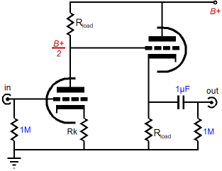
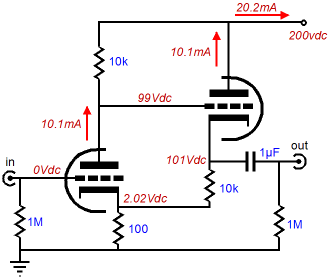
In order to achieve constant-current draw, in the CCDA circuit each triode splits the B+ voltage, so each sees the same cathode-to-plate voltage; and each works into the same load resistance with the same idle current. Thus, total current draw for the two stages equals twice that of either stage individually.
Now here is where the constant-current draw enters the picture. Both the grounded-cathode amplifier and the cathode follower are in voltage phase, but not current phase. For example when the grounded-cathode amplifier sees a positive going input signal, its plate current increases, which increases the voltage developed across the plate resistor, which in turn swings the plate voltage down.
This downward swing is then relayed into the cathode follower's grid, whose cathode follows its grid, reducing the voltage across the cathode follower’s cathode resistor, which in turn causes the cathode follower to decrease its current conduction to the same degree that the previous stage's current increased, as they share the same load resistance. Thus, the net current draw from both stages remains unchanged, although the cathodes and plates might be swinging hugely.
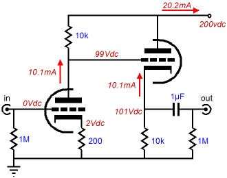
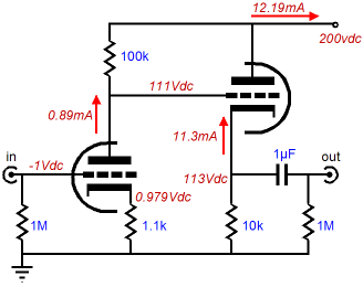
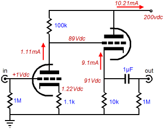
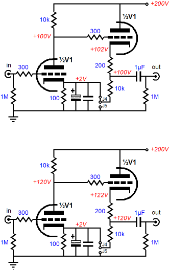
In the examples above, as far as the power supply is concerned, the entire CCDA circuit is nothing more than a 9.9k resistor that conducts a steady 20.2mA from its +200V B+ voltage. Now let’s imagine a non-constant-current-draw circuit.
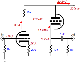
Imagine, in the above circuit, using a dissimilar-triode tube, such as the 12DW7 type tube, wherein a 12AX7 triode is wed to a 12AU7 triode.
Notice how the current draw varies with the signal. Now if the power supply presents a resistance, or worse an impedance -- in other words a frequency-dependent resistance -- then the input signal will be superimposed on the B+ voltage, frequency skewed and phase-shifted, where it will feed back into the first and second stages. Now, doesn’t a constant-current-draw operation by a line amplifier make more sense? Of course, if a perfect power supply were used, then both the constant-current-draw and the non-constant-current-draw line-stage amplifier would perform equally well. (Here's an analogy: if we were absolutely certain that the government was perfectly all-knowing and all-capable, we would all be socialists now...wait a miniute, I forgot that we all were socialists now.)
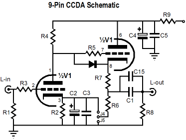
CCDA PCB
Obviously, more components have been added to the basic circuit. Resistor R3 and R5 are grid-stopper resistors and are essential, particularly for the cathode follower output stage. The added diode is also essential, as it protects the second triode at startup, when the cathodes are cold and the cathode follower’s cathode sits at 0V and its grid sees the full B+ voltage—never a good idea, as the cathode can see portions of its surface ripped away by the huge voltage differential. Capacitor C2 and C3 are bypass capacitors, which if used will increase the grounded-cathode amplifier’s gain and improve its PSRR figure, but at the cost of increased distortion. Capacitor C1 is the output coupling capacitor and C15 its small bypass capacitor. C4 and C5 are power supply filtering capacitors which, with resistor R9, define a simple RC filter. Resistor R7 (the extra cathode resistor) is optional, although highly recommended, as its inclusion buffers the cathode follower’s output from heavy capacitive loads and increases the cathode follower’s linearity, but at the cost of increased output impedance. Now for the truly interesting addition: the two jumpers J4 and J5. If J5 is used, resistor R6 terminates into ground and no one is confused. On the other hand, if J4 is used, resistor R6 terminates into the first stage’s cathode resistor and confusion reigns. Here is the history behind the CCDA circuit. Back in the early 1980’s I took up tube electronics in earnest and I conducted many experiments with cathode bypassing. Like many others, I was not happy with the sonic cost incurred by bypassing the cathode resistor. Each capacitor added its own flavor; none was remotely close to perfection. I wanted to know why. So, I attached a scope probe to the top of the cathode resistor and fed the grid a 10kHz square wave. Now, what showed up on the oscilloscope’s screen disheartened me greatly, as the trace did not draw a flat line. Not even close. I tried replacing the cathode resistor with a zener, then an IC voltage reference, then an LED—still the waveform was not perfectly flat. Then I tried using multiple bypass capacitors, which helped, but not enough. I was thinking that fixed-bias with a negative power supply for the grid (or a battery in place of the cathode resistor) was the only answer. Then it came to me: what if the cathode resistor did not experience an AC current flow, but only a DC one? A constant-current flow into a resistor equals a constant voltage; a flat line on the scope, in other words. The next step was to halve the cathode resistor’s value and lift the cathode follower’s cathode resistor off ground and attach it to the grounded-cathode amplifier’s cathode. Bingo, flat line. Okay, this is where most tube gurus would end the story. Whenever you get something seemingly for free, start to worry. Just as those who marry for money usually end up earning it, most free things carry a hidden cost. So, what is the hidden cost with the CCDA circuit? The cathode follower’s current returned to the grounded-cathode amplifier’s cathode is in AC anti-phase with the input stage’s grid, which gives us the net DC current flow into the shared cathode resistor to ground. In DC terms, however, the cathode follower’s current into the grounded-cathode amplifier’s cathode is in phase with the input stage’s plate. If the plate goes positive, the cathode follower conducts more; if it goes negative, less. Thus, if the grounded-cathode amplifier draws too little current, its plate will not center at half the B+ voltage, but climb to a higher voltage. This in turn will cause the cathode follower to conduct more, which will flow into the shared cathode resistor, which will increase the first stage’s cathode-to-grid voltage. All this will further decrease the input tube’s conduction, causing its plate to climb higher. In other words, we've got positive feedback. Well, does the climb to ever-higher plate voltages ever end or does the climb end before reaching the B+ voltage? Stop and think about it: if the input triode is conducting too little and the cathode follower’s triode is conducting too much at idle, how does that differ from when the input tube sees an input signal? In other words, shouldn’t the two tubes still conduct a constant-current at idle? The answer is yes; the sum of currents will equal a constant current conduction, so the shared cathode resistor will continue to experience a constant voltage drop. So what prevents the input’s tube’s plate from wandering about?
If a depletion-mode MOSFETs had been used, little would stop the circuit from drifting, possibly into the power supply rail voltage. Triodes, on the other hand, present an rp that imposes its own negative feedback mechanism, which limits the DC positive feedback and plate wandering. In other words, the CDDA with a common cathode resistor is only slightly more sensitive than a grounded-cathode amplifier to mis-biasing due to the wrong cathode resistor value.
But with less than perfect triodes and cathode followers, the bypass capacitors are still needed, if the common cathode resistor is used and if the CCDA needs to realize its highest gain and best PSSR figure. But at least the cathode bypass capacitor (like the power-supply capacitor) has less work to do, due to the near constant current flow through it. No doubt many applications do require all the gain and the PSRR improvements possible, such an MC cartridge pre-preamp or a mic preamp; but for line-stage amplifier use, the bigger problem is usually too much gain, not too little. Here is a quote from my 1998 CCDA article (note the reference to a "tape deck"!):
For example, a 12AU7-based CCDA line-stage amplifier, with an unbypassed cathode resistor, will deliver a voltage gain of about 8, or 18dB, which is plenty. And the 12AU7 offers a very low mu. A 6N1P will deliver twice the gain or +6dB more, with an unbypassed cathode resistor. Well, in testing the new CCDA PCB I did in fact build up a 12AU7-based CCDA line-stage amplifier, with bypassed cathode resistors.
How did it sound? I found the sonic presentation familiar, as I have built many CCDA line-stage amplifiers over the years. In fact, I was surprised by how good it sounded, no doubt due to the high-quality power supply components, heater regulator, and high-end coupling capacitors. Still, it was no Aikido, sounding only as good as your average $3,000 tube line-stage amplifier ;} I missed the sonic ease and wider sound stage that the Aikido offered. (By the way, I used the exact same 12AU7s and power transformers and chassis that I had used in the Aikido All-in-One line-stage amplifier; so it was oranges versus oranges.) Now, I do acknowledge that some might prefer the slightly edgier sound and that it might better suit some recordings, but I wanted more. Well, more is what I got when I undid the capacitor resistor bypass and used jumper J5 instead. It was an amazing transformation. The sound stage went wide and deep—but the gain went down, an easy price to pay. By the way, see blog 35 and blog 39 for more details on the sonic effects of cathode resistor bypassing.
A good recording to test imaging and layering is Down to the River to Pray sung by Alison Krauss from the movie Oh Brother, Where Art Thou? and available on her A Hundred Miles or More: A Collection album [Rounder UPC 01166105552]. How many distinct singers do you hear accompanying Alison? Or, if you like your grass a little less blue, Ariel Ramirez's masterpiece, Misa Criolla, as sung by the great tenor Jose Carreras on Philips 420 955-1, is also a good choice. (Unfortunately, it may be out of print. And if have never heard this composition before, you will love this recording; but if you have heard any of the Misa Criolla recordings from the late 1960's and early 1970's, it will disappoint greatly, lacking as it is the raw, uncouth energy of the earlier performances—back in the days when jungles were not relabeled "rainforests." Nonetheless, Jose Carreras has never sounded more pure.)
CCDA PCB and Kit
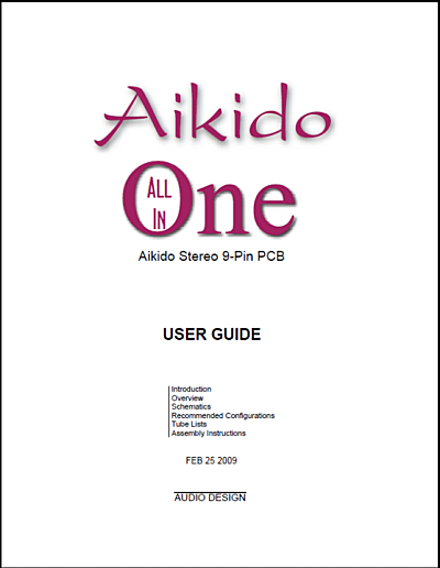
All in One User Guide
Speaking of user guides, I finally made a PDF of the All-in-One user guide, which is a tad ironic, as I have sold out of the All-in-One PCBs and kits. (I create the user guides in a technical drawing program, not a desktop publishing program, so I cannot just press a button and "print" a PDF. Instead, I have to render a new 16-page layout for the PDF.)
New AC Selector Switch
The three positions are: all transformers off, transformer 1 on and transformer 2 off, and both transformers on. With this setup, you can turn on the heater transformer first, so the tubes are given a chance to heat up, which will create an electron cloud over the cathodes, protecting them from the B+ voltage. Or you might want to switch on the line-stage amplifier but not the phono preamp, as why wear out the phono stage’s tubes, when you are listening to CDs? The switch uses redundant contacts and offers a 125Vac and 0.6A rating. It’s available now at the GlassWare Yahoo store and they only cost $6, crazy cheap in other words.
Graigslist: Eight 7591 Tubes Go to Heaven Thanks to Eric Barbour and John Atwood for the following:
Just imagine the fantastic high-end equipment this fellow could design... if the new administration does not snatch him up first, Hidden-Fee Czar or the head of the Department of Inovation for example.
Next Time
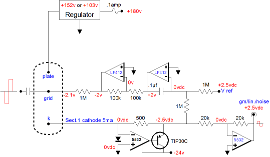
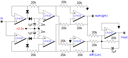
The top circuit cascades into the bottom circuit, a fast rectification circuit, which will deliver the noise, linearity, and transconductance of the tube under test.
//JRB
|
Kit User Guide PDFs
And
High-quality, double-sided, extra thick, 2-oz traces, plated-through holes, dual sets of resistor pads and pads for two coupling capacitors. Stereo and mono, octal and 9-pin printed circuit boards available.
Designed by John Broskie & Made in USA Aikido PCBs for as little as $24 http://glass-ware.stores.yahoo.net/
The Tube CAD Journal's first companion program, TCJ Filter Design lets you design a filter or crossover (passive, OpAmp or tube) without having to check out thick textbooks from the library and without having to breakout the scientific calculator. This program's goal is to provide a quick and easy display not only of the frequency response, but also of the resistor and capacitor values for a passive and active filters and crossovers. TCJ Filter Design is easy to use, but not lightweight, holding over 60 different filter topologies and up to four filter alignments: While the program’s main concern is active filters, solid-state and tube, it also does passive filters. In fact, it can be used to calculate passive crossovers for use with speakers by entering 8 ohms as the terminating resistance. Click on the image below to see the full screen capture.
Tube crossovers are a major part of this program; both buffered and un-buffered tube based filters along with mono-polar and bipolar power supply topologies are covered. Available on a CD-ROM and a downloadable version (4 Megabytes). Download or CD ROM
|
|||


| www.tubecad.com Copyright © 1999-2009 GlassWare All Rights Reserved |