John Broskie's Guide to Tube Circuit Analysis & Design
07 March 2009

TCJ 10 Year Anniversary
In March of 1999 the Tube CAD Journal was born. I had been writing the Tube Circuit of the Month articles for my GlassWare website and the response was just tremendous. This surprised me, as schematics were not rare on the Web, but enthusiasm-dripping e-mails I received told me that something extra was going on. I asked and the answer I got was that I just didn’t show how a circuit was laid out; I explained why it was designed that way. I realized that something more than one short article a month was needed. Thus the Tube CAD Journal was created. It, however, did not become what I had intended, as I wrote back in 2002 in an answer to a TCJer’s letter:

The original intent of this journal was to mimic the Math CAD Journal, a magazine put out by the MathSoft people to assist users of their Math CAD program by providing math-related articles that illustrated how their software could be used. For example, users of Math CAD who explain how they found the program useful write many of the articles. Well that was the intent, but the Tube CAD Journal went off in another direction altogether. Part of the reason was that many of the tube fanciers needed, as you pointed out, to be technically brought up to speed. Another part was my hope of expanding the tube-audio horizon, which I felt was collapsing into a few simple-minded topologies and practices.


Trying to put out a one-man-operation webzine, with an occasional helping hand from John Atwood, was thrilling, but exhausting. From webzine to just single articles to blog entries was the path I had to follow to save my sanity. Yes, I know that blog is not a proper blog, being to infrequent and being too long. But this format is a comfortable one and it is here to stay.

So here I am, as Thomas Stearns E. might have put it, in the middle way, having had ten years—ten years largely wasted, the years of l'entre deux enfants terribles. Trying to use words to describe circuits, and every attempt is a wholly new start, and a different kind of failure. Because I have only learned to get the better of words for the circuits I no longer wish to explicate, or the way in which I am no longer disposed to say it. And so each blog entry is a new beginning, a raid on the enigmatic, with shabby equipment always deteriorating in the general mess of imprecision of high-end audio—undisciplined squads of fabricated rumor, advertising myths, and science most pseudo. And what there is to conquer, by acumen and acquiescence, has already been discovered once or twice, or several times, by men whom one cannot hope to emulate—but there is no competition—there is only the fight to recover what has been lost and found and lost again and again; and now, under conditions that seem unpropitious, but perhaps neither gain nor loss. For me, there is only the trying. The rest is not my business.


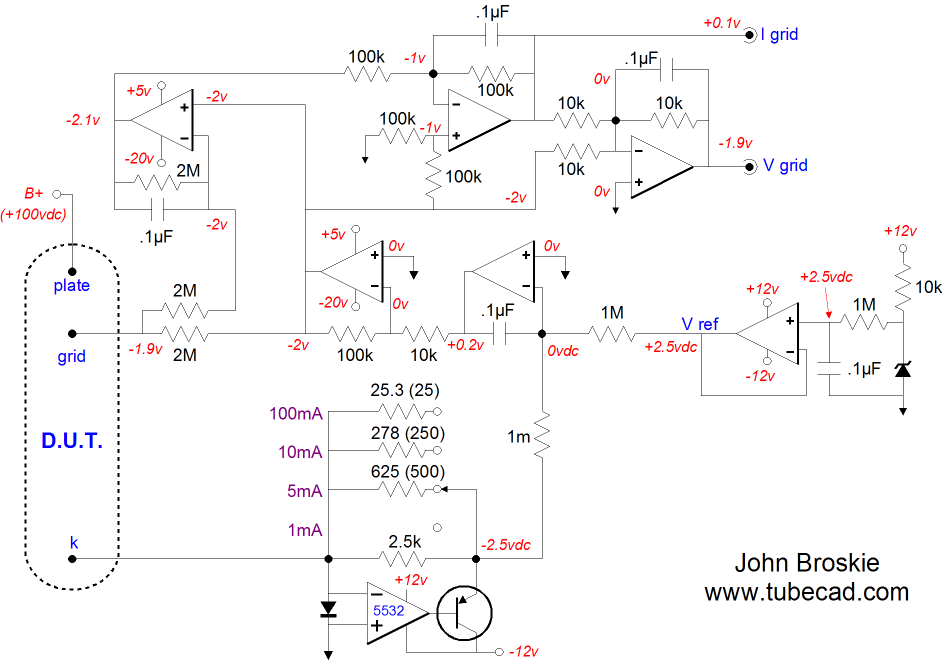
Tube Tester: Ig & Vg
Back to testing tubes. Last time we saw how an auto-bias circuit could be implemented that forced the tube under test to conduct a fixed current by adjusting its grid voltage, while its cathode-to-plate voltage remained fixed. (Had we tried a constant-current source in series with the cathode, the cathode-to-plate voltage would decrease by the cathode voltage, which would throw our results off; maybe not a lot with a 12AX7, but by a huge amount with a 6AS7.) Now, we look at how we can derive some useful information with the auto-bias circuit, such as the grid voltage and the grid current.

auto grid-bias voltage setter

In the schematic above, we see three extra OpAmps. With these OpAmps we can extract the voltage drop across the two 2M resistors that attach to the grid. Now, 2M in parallel with 2M equals 1M, so any voltage that develops across these resistors will reveal a current flow equal to V/1M. Thus, for example if we measure 2V, then 2/1000000 milliamperes of current flows through the 1M resistance. In addition, this circuit allows us to measure the exact voltage at the grid, without dragging down that voltage in the process of measuring.

The four-position switch allows us to set the desired idle current. At the first position, there is no resistor and the NE5532 OpAmp sees only the 2500-ohm feedback resistor. At the second position, the 625-ohm resistor is in parallel with the 2500-ohm resistor, which means that the OpAmp effectively sees 500-ohm feedback resistor. Because the auto-bias circuit will strive to maintain an output voltage of -25Vdc for the bottommost OpAmp, the current flowing through the feedback resistor (and by extension, the tube under test) must equal 2.5/Rfb. Thus, for example, 2.5/500 equals 5mA.

The voltage reference is made up from a buffered voltage-reference IC, whose set voltage is 2.5V. To be honest, the RC filter that following the voltage reference is just so much extra frosting and it can be left out.

One last feature worth mentioning is that while most of the OpAmps see a +/-12V power supply, the two OpAmps closest to the grid work off of +5V and -20V rails. Why? The tester needs to be able to control a wide range of tubes, so extra negative grid bias voltage is needed and at no time should we expect a tube to need positive grid bias. At the time I designed this tester, I preformed a survey of output tubes and I concluded that with only 150Vdc for a cathode-to-plate voltage all the tubes would be able to idle at 100mA with a grid voltage not less negative than -19V; perhaps I was wrong. More testing is required.


Next Time
We will look into how to measure transconductance, noise, and linearity. And I hope to announce the arrival of more PCBs.

Since I began with T.S. Eliot, maybe I should end with what my fellow Capricorn, Henry Miller might have written about the Tube CAD Journal: What is this then? This is not a tube-Wiki website. This is useful, original, sonically sound. This is not an electronics website, in the ordinary sense of the word. No, this is a prolonged cheat sheet, a gob of hot solder in the face of high-end audio, a kick in the pants to proprietary circuits, Audio Research, Conrad Johnson, VTL, MJ, AudioXpress… what you will. I am going to spill the beans for you, a little sloppy perhaps but I will spill.


//JRB


Kit User Guide PDFs
Click image to download

BCF User Guide

Download PS-3 User Guide

Janus regulator user guide

E-mail from GlassWare Customers

Hi John,

I received the Aikido PCB today - thank you for the first rate shipping speed.
    Wanted to let you know that this is simply the best PCB I have had in my hands, bar none. The quality is fabulous, and your documentation is superb. I know you do this because you love audio, but I think your price of $39 is a bit of a giveaway! I'm sure you could charge double and still have happy customers.
     Looking forward to building the Aikido, will send some comments when I'm done!
   Thank you, regards
Gary


Mr Broskie,

I bought an Aikido stereo linestage kit from you some days ago, and I received it just this Monday. I have a few things to say about it. Firstly, I'm extremely impressed at the quality of what I've been sent. In fact, this is the highest quality kit I've seen anywhere, of anything. I have no idea how you managed to fit all this stuff in under what I paid for it. Second, your shipping was lightning-quick. Just more satisfaction in the bag, there. I wish everyone did business like you.

Sean H.


9-Pin & Octal PCBs

High-quality, double-sided, extra thick, 2-oz traces, plated-through holes, dual sets of resistor pads and pads for two coupling capacitors. Stereo and mono, octal and 9-pin printed circuit boards available.

Designed by John Broskie & Made in USA

Aikido PCBs for as little as $24

http://glass-ware.stores.yahoo.net/


Support the Tube CAD Journal
&
get an extremely powerful push-pull tube-amplifier simulator for

Only $29

TCJ Push-Pull Calculator
Version 2


Click on images to see enlargements


TCJ PPC Version 2 Improvements

       Rebuilt simulation engine
       Create reports as PDFs*
       More Graphs 2D/3D*
       Help system added
       Target idle current feature
       Redesigned array creation
       Transformer primary & secondary
              RDC inclusion
       Save user-defined transformer     
              definitions
       Enhanced result display
       Added array result grid

                                       *User definable


TCJ Push-Pull Calculator has but a single purpose: to evaluate tube-based output stages by simulating eight topologies’ (five OTL and three transformer-coupled) actual performance with a specified tube, power supply and bias voltage, and load impedance. The accuracy of the simulation depends on the accuracy of the tube models used and the tube math model is the same True Curves™ model used in GlassWare's SE Amp CAD and Live Curves programs, which is far more accurate than the usual SPICE tube model.

Download or CD ROM
Windows 95/98/Me/NT/2000/XP

For more information, please visit our Web site :
          
www.glass-ware.com

To purchase, please visit our Yahoo Store:
http://store.yahoo.com/glass-ware


www.tubecad.com           Copyright © 1999-2009 GlassWare           All Rights Reserved