John Broskie's Guide to Tube Circuit Analysis & Design
24 October 2009


Tube Phono Preamplifier with Passive RIAA Eq


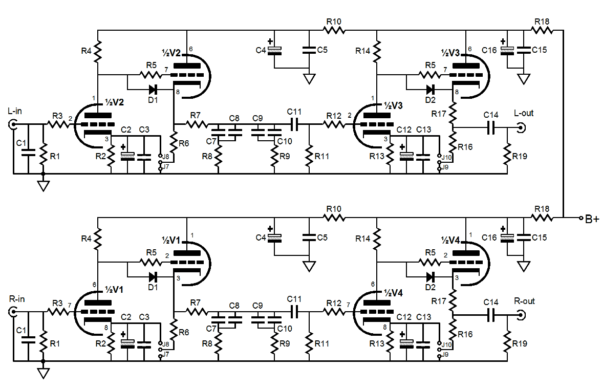
Introducing the Tetra Phono Preamp
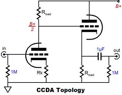
Somewhat along the lines of the last blog entry’s walk down Nostalgia Lane, I must admit that I find the LP’s allure powerful. I love the cover art, the shiny black vinyl and center labels, the obvious retro charm of carefully choosing an LP to play, removing the LP, holding it gingerly by its edges, performing ritual rites of ablution with cleaners and brushes, watching it spin and, finally, listening to it. I love the time-machine aspect of old records, as they let us hear what was heard 50, 60 years ago, as it was heard then. I like listening to music that missed the translation into digital; many LPs never were rereleased as CDs. In my own collection, 75% does not have a CD equivolent and 50% were never released in CD format. Moreover, I both like and dislike the how the LP demands our attention, how you must choose which side to play, and what to play next, as the paltry 22 minutes does not give you much of a respite. Music should be attended to in a thoughtful way and playing LPs requires ten times more thought and effort than listening to a music server or the radio. In other words, LPs will never cease to spin—nor will they ever predominate again, although the sale of LPs is actually up this year over last year, as the ease of a CD or MP3 player or music server is far too compelling.


CCDA Topology
The CCDA’s low distortion, fairly high gain, and low output impedance—all are desirable attributes in a phono preamp. The Constant-Current-Draw Amplifier is a compound circuit that holds a grounded-cathode amplifier directly cascaded into a cathode follower. So what; what's so special about this obvious pairing? Its special status lies in the details. Each triode sees the same cathode to plate voltage and the same load resistance and same idle current draw. Both the grounded-cathode amplifier and the cathode follower are in voltage phase, but in anti-current phase. For example, as the grounded-cathode amplifier sees a positive going input signal, its plate current increases, which increases the voltage developed across the plate resistor, which in turn swings the triode’s plate voltage down. This downward voltage swing is then cascaded into the grid of the cathode follower, whose cathode follows its grid’s downward swing, which decreases the current through the cathode follower to the same degree that the previous stage's current increased. This results in the constant current draw feature of this topology (a highly desirable feature, as the signal amplification will not alter the amount of current being sourced from the power supply and consequently not perturb the power supply, thus greatly simplifying the design consideration of the power supply).

Calculating the gain from a CCDA amplifier is easy, when the cathode resistor is left un-bypassed, as the gain roughly equals half the mu of the input triode used. For example, a 12AX7 holds a mu of 100, so the gain will equal 50 (+34dB). The gain from a simple grounded-cathode amplifier, with a bypassed cathode resistor, is a bit more complicated

     Gain = muRa / (rp + Ra)

For example, given a 12AX7 loaded by a 150k plate resistor and whose capacitor resistor is bypassed, the gain will roughly equal 70 (+37dB).

The passive equalization network entails a -20dB insertion loss, which must be subtracted from the combined gain from the two CCDA gain stages. For example, two 12AX7-based, +34dB gain stages deliver a final gain of +68dB -20dB, which equals +48dB. Of course, the cathode followers also exact a slight loss of gain, so in the example just given, the final gain would be closer to +44 to 46dB.


Alternate Cathode Resistor Connection
For the advanced practitioner, the Tetra All-in-One phono PCB accepts two ways of bypassing the grounded-cathode amplifier’s cathode resistor.

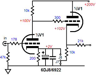
The first is to use jumper J7 (and J9 for the final CCDA gain stage) and capacitors C2 & C3. This the standard way that 99.99999% of tube circuits are wired.

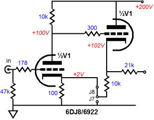
The second approach is to use jumper J8 (and J10 for the final CCDA gain stage) and forgo the bypass capacitors. This configuration requires halving the cathode resistor’s nominal value, as twice the current will flow through the resistor. The resistor is effectively bypassed, however, as anti-phase AC current flows from the cathode follower side of the circuit into the cathode resistor, effectively establishing a DC current flow and constant voltage drop across the resistor. (In reality, a small amount of AC current signal will superimpose a small AC signal across the resistor.) Just as we can wear a belt with suspenders, the bypass capacitors can be added to this configuration. But do first try it without the capacitors. I have become quite senstive to the sonic overlay that cathode resistor bypass capacitor adds to the sound from a circuit.
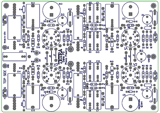

Click on schematic to see closeup


Tetra PCB
The Tetra's FR-4 PCB is extra thick, 0.094 inches (inserting and pulling tubes from their sockets won’t bend or break this board), double-sided, with plated-through 2oz copper traces, and the boards are made in the USA. The Tetra PCB holds two phono-stage preamplifiers, with each phono preamp holding two CCDA gain stages with a passive RIAA equalization circuit in between. Thus, one board is all that is needed for stereo use. The boards are six inches by ten inches, with seven mounting holes that prevent excessive PCB bending. They are on sale now at the GlassWare Yahoo store and come with a 16-page user guide.

They cost $49 USD—a great bargin, in other words. Additional parts for the Tetra, such as tube sockets, tubes, and power-supply parts, are also available at the GlassWare Yahoo store.
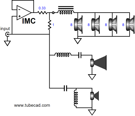


Broskie Impedance Multiplier
The impedance-multiplier topic has proved to be a much thicker vein than I expected. I never thought that I would or could post four times on the impedance-multiplier circuit (IMC), but no doubt I could post another four. Don’t worry; I don’t plan on doing so, as I am sure that most TCJers need some time to digest what has already been posted. For myself, I am quite tickled by the idea of incorporating a power IMC into a loudspeaker enclosure to help the wimpy external tube power amplifier drive 2-ohm woofer arrays.

Imagine a class-D amplifier configured as an IMC and four 8-ohm long-throw, low resonance, low efficiency woofers in parallel. Quadrupling the woofer surface area will result in +12dB increase in efficiency, if all the drivers see the same voltage across their leads. Thus, if we start with 88dB woofers, we effectively end up with a 100dB woofer that can move four times more air, providing much deeper and powerful bass performance than we would expect from a relatively small enclosure. Our wimpy tube amplifier could never drive the 2-ohm load directly, but with the aid of the high-power IMC, it does not have to. By the way, a 2-ohm load is great news for the series inductor used in the woofer’s crossover, as it need only be one fourth the value that an 8-ohm woofer would otherwise require.

Yes, a passive crossover would still be required. Just imagine a fairly small loudspeaker with 100dB efficiency (horn midrange and tweeter) and super-sweet, flea-power, single-ended amplifier, say 2A3 or 300B filled. This is the stuff that dreams are made of.

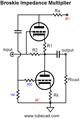
I have come up with an interesting tube-based IMC, which I shamelessly have named the Broskie Impedance-Multiplier. The circuit offers push-pull impedance multiplying, with top and bottom triodes responding to the AC current signal presented at its input.

Once again, start by imagining a load of 0-ohms, a dead short to ground, in other words. A positive-going input current will develop a positive-going input voltage for the top triode, which will increase its conduction, thereby creating a negative-going input signal for the bottom triode’s grid, which will decrease its conduction. A negative-going input current will develop a negative-going input voltage for the top triode, which will decrease its conduction, thereby creating a positive-going input signal for the bottom triode’s grid, which will decrease its conduction. In a nutshell, push-pull operation; the delta in currents between top and bottom tubes will flow into and out of the ground connection.

Yes, I know it looks a lot like a White cathode follower, but it doesn’t function like one. First, unlike with a White cathode follower, the input and output are not independent of the signal source and load impedance. For example, with the 0-ohm load, the Broskie impedance multiplier’s input impedance will equal resistor R2’s value, hardly the near infinite input impedance that the White cathode follower presents. And a high-impedance signal source will yield a high output impedance from the impedance multiplier, not the constantly low impedance offered by the White cathode follower. Remember, an IMC is not a unity-gain buffer or a voltage amplifier; it is something altogether different.

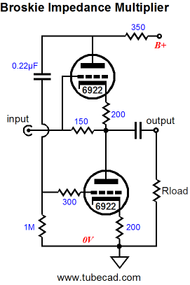
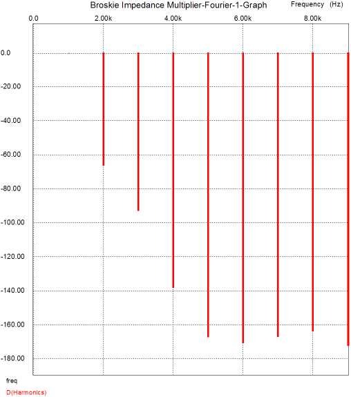
The above schematic reveals a design example that uses a 6DJ8/6922/ECC88/6N23P/6N11 type tube and provides symmetrical current swings from both triodes into the load and multiplies the load impedance by roughly 2. The following graph is from a SPICE simulation with a 1Vpk swing into 300-ohm load at 1kHz.


//JRB


Kit User Guide PDFs
Click image to download

BCF User Guide

Download PS-3 User Guide

Janus regulator user guide


E-mail from GlassWare Customers

Hi John,

I received the Aikido PCB today - thank you for the first rate shipping speed.
    Wanted to let you know that this is simply the best PCB I have had in my hands, bar none. The quality is fabulous, and your documentation is superb. I know you do this because you love audio, but I think your price of $39 is a bit of a giveaway! I'm sure you could charge double and still have happy customers.
     Looking forward to building the Aikido, will send some comments when I'm done!
   Thank you, regards
Gary


Mr Broskie,

I bought an Aikido stereo linestage kit from you some days ago, and I received it just this Monday. I have a few things to say about it. Firstly, I'm extremely impressed at the quality of what I've been sent. In fact, this is the highest quality kit I've seen anywhere, of anything. I have no idea how you managed to fit all this stuff in under what I paid for it. Second, your shipping was lightning-quick. Just more satisfaction in the bag, there. I wish everyone did business like you.

Sean H.


9-Pin & Octal PCBs

High-quality, double-sided, extra thick, 2-oz traces, plated-through holes, dual sets of resistor pads and pads for two coupling capacitors. Stereo and mono, octal and 9-pin printed circuit boards available.

Designed by John Broskie & Made in USA

Aikido PCBs for as little as $24

http://glass-ware.stores.yahoo.net/


Support the Tube CAD Journal

&

get an extremely powerful push-pull tube-amplifier simulator for

Only $29

TCJ Push-Pull Calculator
Version 2


Click on images to see enlargements


TCJ PPC Version 2 Improvements

       Rebuilt simulation engine
       Create reports as PDFs*
       More Graphs 2D/3D*
       Help system added
       Target idle current feature
       Redesigned array creation
       Transformer primary & secondary
              RDC inclusion
       Save user-defined transformer     
              definitions
       Enhanced result display
       Added array result grid

                                       *User definable


TCJ Push-Pull Calculator has but a single purpose: to evaluate tube-based output stages by simulating eight topologies’ (five OTL and three transformer-coupled) actual performance with a specified tube, power supply and bias voltage, and load impedance. The accuracy of the simulation depends on the accuracy of the tube models used and the tube math model is the same True Curves™ model used in GlassWare's SE Amp CAD and Live Curves programs, which is far more accurate than the usual SPICE tube model.

Download or CD ROM
Windows 95/98/Me/NT/2000/XP

For more information, please visit our Web site :
          
www.glass-ware.com

To purchase, please visit our Yahoo Store:
http://store.yahoo.com/glass-ware

 
www.tubecad.com           Copyright © 1999-2009 GlassWare           All Rights Reserved