| John Broskie's Guide to Tube Circuit Analysis & Design |
06 January 2010
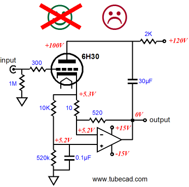
SuperTriodes Since posting blog 178, I went digging through my old SPICE simulation files and I found that the last circuit in that blog wasn’t the stellar performer I had mistakenly remembered it being. The circuit was an attempt to wed a SuperTriode to an OpAmp or a GainClone power amplifier. This last circuit’s stated goal was vastly improved safety, but its primary and implicit goal was low-distortion. Well, the design was safer, but its AC performance was poor, at least in SPICE simulations. What went wrong?
In DC terms, the triode and solid-state power amplifier perform perfectly, with the solid-state power amplifier’s output being DC-offset free, even with the tube removed from the circuit. In AC terms, however, the triode must work into the 10-ohm load at its cathode, which is far too low in value to provide sufficient local negative degeneration. The ideal cathode load would be infinity, such as a constant-current source would present; 10-ohms falls quite a bit short of infinity. The workaround is to increase the cathode load resistance’s value to something much larger, say 1kohm.
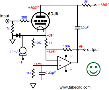
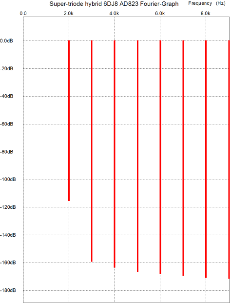
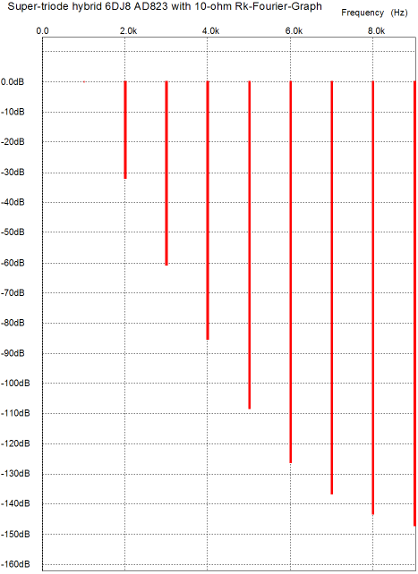
If we increase the resistor to 1k, then we must also increase the 520-ohm feedback resistor to ensure that the solid-state amplifier’s gain exceeds the triode’s mu. In the example shown above, the feedback resistor’s value has been increased to 100k, which results in a gain of 100 for the solid-state amplifier. Thus, the triode sees in DC terms a cathode resistor that consists of the four resistors, (10k + 1M) || (1k + 100k), which equals a DC resistance of 91.8k. By itself, a 91.8k cathode resistor would starve the triode of any current, thus the need for the 10mA constant-current source that also attaches to the cathode. The diode will provoke much mental anguish, which almost compelled me to leave it out of the schematic, but its inclusion is a nice safety feature. Under normal operation, with the triode hot and conducting current, the diode simply drops out of the circuit, as it conducts no current, being backward biased, with its anode more negative than its cathode. But at startup, when the tube is cold and non-conducting, the diode becomes forward-biased and conducts the 10mA of current provided by the constant-current source, thereby limiting the constant-current source’s downward voltage tug to only about negative 0.7Vdc. In other words, the diode is there to protect the triode from excessive positive grid-to-cathode voltage and, thus, possible cathode stripping and to prevent the solid-state amplifier from going into a latch-up mode. Ten cents very well spent, in my opinion. Below, is a graph from a SPICE simulation of the circuit shown above, delivering 1Vpk @ 1kHz into a 1k load.
Not bad. The question that must be asked is, How much better is this configuration compared to the first version with the 10-ohm cathode resistor? The graph below shows how much more distortion the 10-ohm cathode results in.
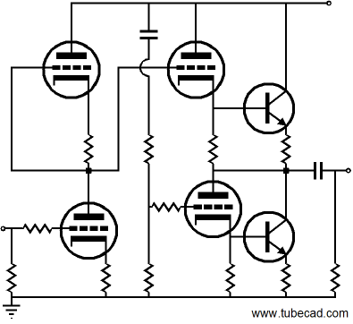
SuperTriode Meets the Aikido With all this in mind, the following circuit will make more sense. The Aikido’ output stage has received a serious supercharging, as the two new transistors allow the output to swing much heavier current swings into low-impedance loads.
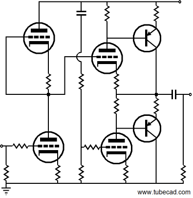
Even with the transistor's relatively low turn-off voltage, the voltage drop across the Aikido's output stage's cathode resistors may not prove sufficient to turn on the NPN transistors. One possible workaround is to use PNP transistors instead of NPN types, as we enjoy much more freedom to adjust the plate resistor values.
Electrostatic Speakers
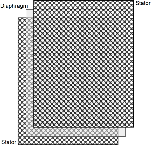
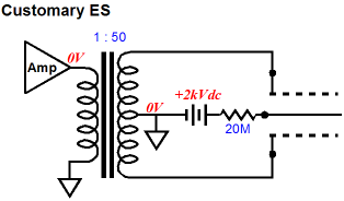
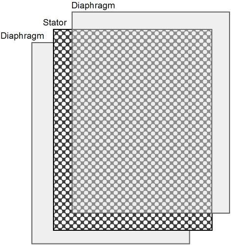
The stators receive a push-pull signal from a step-up audio transformer and the diaphragm sees a polarizing voltage, delivered from a high-voltage/low-current power supply. This polarizing voltage is usually well over 1kV; the greater the bias voltage, the higher the efficiency—up to a point, thereafter the efficiency flattens. The diaphragm attaches to the high voltage power supply via a high-ohmage series resistor, whose value can span from 10M to 200M. This resistor greatly limits the inrush current into the diaphragm at startup, as the electrostatic loudspeaker builds up its static charge. This resistor also creates a constant-charge relationship within the electrostatic loudspeaker, wherein the diaphragm’s static voltage charge remains steady in spite of the music signal superimposed upon the stators, which greatly reduces the loudspeaker’s distortion. (If the electrostatic loudspeaker didn’t slowly lose its charge due to humidity and dust and insulating tape’s microscopically small trace of conductivity, the diaphragm could be charged up at the factory and shipped without the series resistor and high-voltage power supply, as the speaker would sustain its polarizing charge forever.)
When music signal is applied to the stators, the diaphragm moves from one stator to the other, as it traces the signal’s movement from positive to negative. It does so because like charges repel each other and dissimilar charges attract each other. So, as one stator swings positively, the other swings negatively; and the diaphragm is drawn to one stator and repelled by the other alternately. By the way, the first electrostatic loudspeakers only held one stator. The audio signal was applied to the single stator and high-voltage polarized diaphragm moved closer and further away from the stator, as the voltage relationships between it and the stator changed. This arrangement produced a strong 2nd harmonic distortion, as the single stator’s influence on the diaphragm varied with the square of the distance between them. In other words, as the stator tugged the diaphragm closer to itself, its tug grew stronger, but when it repelled the diaphragm, its push fell off, as the diaphragm moved further away from the stator. Adding the second stator and the push-pull drive voltages resulted in greatly linearizing the stators’ control over the diaphragm. Nonetheless, this old design might still offer some sonic rewards. For example, if the single-stator electrostatic loudspeaker were driven by a single-ended amplifier with a strong 2nd harmonic distortion, the two in tandem might iron out each other’s nonlinearities. Of course, if incorrectly phased, the combination would prove doubly distorted. This has been a nutshell explanation of the conventional electrostatic loudspeaker and we can now move on to the inverted electrostatic loudspeaker.
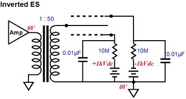
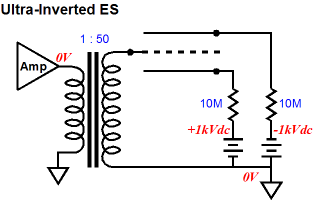
Inverted Electrostatic Loudspeakers The inverted electrostatic loudspeaker reverses all the roles, except for the insulating tape’s role within an electrostatic loudspeaker. The stators no longer see the audio signal and the diaphragm is driven instead.
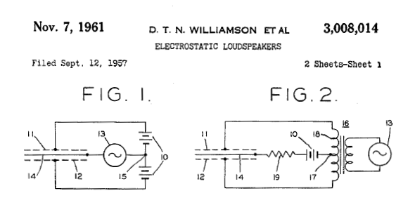
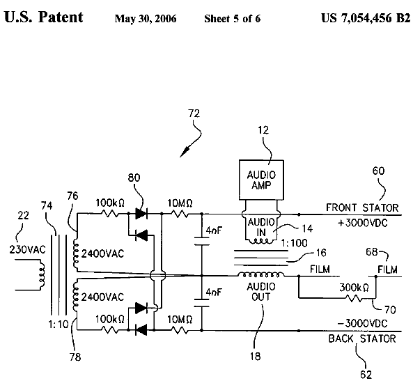
Because the diaphragm receives the audio signal, it can no longer use a super-high-impedance conductive coating, which can be seen as an improvement, as metalized plastic film can used and conductive spray paint is readily available, albeit at great cost (some conductive paints sell for hundreds of dollars per liter). Moreover, a diaphragm could be made from two layers of film, with a layer of conductive paint in between, which would greatly increase the diaphragm’s safety, as the conductive center would be insulated by the two layers of plastic film. In addition, this design would solve both big problems, that of the graphite falling off the diaphragm and of the dust collecting on the diaphragm. The stators must now be polarized by two high voltage power supplies, as one must be charged positively, while the other is charged negatively. And two high-ohmage series resistors will be needed, as they provide inrush current limiting and lessen the damage that can be caused should the diaphragm slap against a stator. Williamson and Walker claim in their patent that design goal of a constant charge operation of the electrostatic loudspeaker is not possible with the inverted ES speaker, hence their creation of the constant-charge ES speaker with the stators being driven by the audio signal. I am not completely convinced that they are right, as adding two external shunting capacitors to the inverted electrostatic loudspeaker, which are required to keep the stators from following the diaphragm voltage swings, will establish a constant charge across the stators. (By the way, imagine if the stators were made from perforated PCB material, with copper cladding on both sides. Now imagine that the outside side of the stator had its copper coating grounded and the inside side's copper saw the polarizing voltage. In such an arrangement, the stator would define a capacitor in itself—stator qua shunting capacitor. Of course, the PCB material would not be the typical FR-4 stuff, but Teflon. I imagine that this would make an excellent and safe headphone design.) The diaphragm attaches to single-ended step-up transformer and it must see twice the signal voltage that the each stator saw in the conventional electrostatic loudspeaker. But at the same time, each stator can see half the polarizing voltage that the diaphragm saw in the conventional electrostatic loudspeaker. By the way, in 2006, Maarten Smits and Hidde W. de Haan were awarded US patent No. 7,054,456 for their “Invertedly driven electrostatic speaker.”
In their patent, the inventors claim that their inverted electrostatic loudspeaker offers much greater efficiency, thereby greatly decreasing the needed voltage swings. I cannot understand why this would be so, but then I have only conceptual tools to apply, not having built a working model of an inverted electrostatic loudspeaker. By the way, back in the mid 1970s, I came up with my own inverted electrostatic loudspeaker design concept. I was interested in possibility of making an electrostatic subwoofer. My thinking was that if the loudspeaker frequency response were limited to about 100Hz, a power transformer (driven backwards) could readily be used as the audio step-up transformer; in addition, at 100Hz, even the most capacitance-heavy electrostatic loudspeaker (I wanted an eight-by-four-foot panel) would nonetheless present a very high reactance, which would not drag down the power amplifier. My big fear was sparks and burning diaphragms, when the diaphragm slaps against a stator, which would be quite likely in a subwoofer application. My workaround was an inverted electrostatic loudspeaker, but a truly inverted electrostatic loudspeaker. I imagined a perforated stator in the center, flanked by two diaphragms.
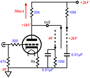
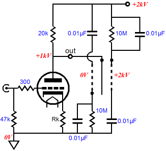
The diaphragms would move in unison, both pushing forward and backward in phase with each other. The conductive coating would be applied to the diaphragm’s outside surface, so the plastic film would insulate the coating, thereby protecting the diaphragms from directly touching the stators. Moreover, since the high frequency limit would be so low in the subwoofer, a much thicker and massive plastic film could be used. I tried to build a working model, but I gave up once I realized that I didn’t have access to the required tools or materials. (For example, I couldn’t find perforated sheet metal that was truly flat and not filled with sharp burs; I imagined that soaking the stator in acid would de-bur the metal nicely, but I had no idea how to render it flat.) Okay, returning to the topic of plain inverted ES speakers, we have inverted the conventional electrostatic loudspeaker's mode of operation, but what have we really gained? Always a good question to ask. The answer is that we can now apply many different circuits to drive the inverted electrostatic loudspeaker that would not have been possible with the conventional electrostatic loudspeaker. The above schematic shows one possible example. The power triode attaches directly to the diaphragm and the B+ voltage and ground provide the polarizing voltages for the stators. Note how the voltage relationships within the example above are no different than in the first example of an inverted electrostatic loudspeaker, as the diaphragm sits at 1kV higher than one stator and -1kV lower than the other.
One problem with the single-ended amplifier is that power-supply noise will appear at its output and this noise will not cancel as it would in push-pull setup. An electrostatic loudspeaker that hums away is no one’s idea of a good time. Using a better power supply, perhaps even a regulated power supply, can only help, but wouldn’t be better just to sidestep the power-supply noise problem altogether? I am sure you can guess what I am about to propose: an Aikido-like technique that nulls the noise within the electrostatic loudspeaker itself.
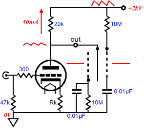
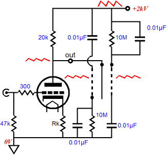
The two extra capacitors create two AC voltage dividers, which in this example halve the power-supply noise at the stators. Since the triode and its plate resistor also define a 50% voltage divider, the diaphragm and stators now all see the same amount of power-supply noise, which means that where there is no difference, there can be no distinction. Had the triode’s cathode resistor been bypassed by a large capacitor, then the voltage divider ratio would fall to rp / (rp + Ra) and the added capacitors would have to be scaled accordingly to restore the power-supply noise null.
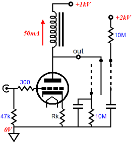
By the way, adding a small-valued cathode bypass capacitor might prove a great plus, as it would boost the triode’s high frequency output, just as the electrostatic loudspeaker’s capacitance begins to drag down the triode’s high frequency output. In other words, the added cathode bypass capacitor’s value must be carefully chosen to produce the desired result, as too big a capacitor value will create mid-frequency hump in the frequency; too low a value will create a mid-frequency dip; and the correct value will extend the high frequency of the electrostatic loudspeaker and triode-based OTL power amplifier. Another "by the way": the resistor-loaded single-ended amplifier is amazingly inefficient, as the plate resistor dissipates more heat than the power tube. Replacing the plate resistor with an inductor will easily double the power amplifier’s efficiency.
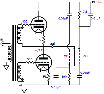
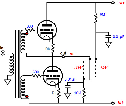
Note how the capacitor voltage dividers are no longer needed, as the choke load effectively shields the triode’s plate from the power-supply noise. Designing a push-pull OTL power amplifier to drive the inverted electrostatic loudspeaker is only a little more difficult. And if we use an inter-stage audio transformer, it becomes a piece of cake.
Two identical power triodes are used, each using the same valued cathode resistor and its own heater winding. The inter-stage audio transformer provides the necessary phase splitting and extra voltage gain. This push-pull amplifier could be run in either class-A or rich class-AB. It could also be used with a bipolar power supply, which held -1kV and +1kV power supply rails. In such a setup, the two capacitor voltage dividers would no longer be needed, as the power-supply noise would automatically null at the push-pull amplifier’s output (at least it would in the amplifier's range of class-A operation); and the stator voltages would consist of -1kV and +1kV polarizing voltages.
Next Time
//JRB |
Kit User Guide PDFs
E-mail from GlassWare customers:
And
High-quality, double-sided, extra thick, 2-oz traces, plated-through holes, dual sets of resistor pads and pads for two coupling capacitors. Stereo and mono, octal and 9-pin printed circuit boards available.  Aikido PCBs for as little as $20.40 http://glass-ware.stores.yahoo.net/ Only $19.95
Download or CD ROM
|
|||


| www.tubecad.com Copyright © 1999-2010 GlassWare All Rights Reserved |