| John Broskie's Guide to Tube Circuit Analysis & Design |
| 19 April 2010
PCBs & Tube Clock Update
Tringlotron: An Interesting New Topology Waitron? What the hell is a waitron? Shame on you; you will never make federal community organizer, 1st class. One politically correct term for a waiter or waitress is "waitron." And no doubt, some readers with children wonder why I left off the list "Megatron," the leader of the evil faction in Transformers cartoons and toys; laziness, nothing more. Yep, any electronic device that ends in "tron" sound spiffy to my ears. So much so that I must name my next new topology the ___tron. Oops, I am sure that I am digressing too much here. After a bit of web searching, I found that the Tringlotron topology is reported to have been created by a Ludwig Von Bürnmoll and that this topology is related to a Biglotron, of which I know nothing and no amount of Googling yielded any results. The word "Tringlotron" is a contraction of TRIplet of NPNs Grouped in Line. I first read about this topology in April 8th issue of Electronic Design magazine in an article titled, "Novel Buffer Topology Cancels Nonlinearities," by Louis Vlemincq. The circuit shown in the article used three transistors to create a super-fine unity-gain buffer, but as Mr. Vlemincq rightly points out that the topology can be applied to many other device types, even tubes.
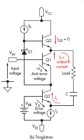
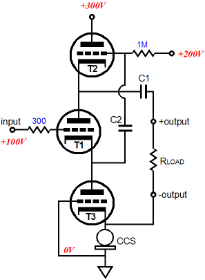
If you have ever employed a simple emitter follower in an audio circuit, no doubt you have been as disappointed as I have been by the fairly poor results. Surely—with all the screaming transconductance a transistor offers and with the 100% degeneration presented by the follower topology—much better performance should be obtainable, surely lower distortion and a closer approximation to unity gain should be readily delivered, but aren't. This has led me to building compound followers that use NPN and PNP transistors to achieve the performance potential I desired. I am not alone, which is why the Tringlotron was created. In the example cited in the Electronic Design article, the distortion reduction was more than 50 times better in the three-transistor buffer compared to the single transistor emitter follower; and the output impedance was 32 times lower. Now, this is change I can actually believe in. Translating the Tringlotron into glass is easy enough, as the schematic below illustrates.
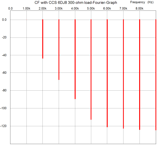
Where a cathode follower uses one triode and a White cathode follower and Aikido cathode follower use two triodes, the Tringlotron uses three. That's a lot of triodes and a lot of B+ voltage and an internal coupling capacitor and a constant-current source and a lot of headaches due to the hassle required to stay within the triode's heater-to-cathode voltage limits, so we should expect some real results. Do not worry, results are there aplenty. (In addition, do not worry too much about this topology not making any sense at first; it will.) Note that the coupling capacitor to the load has been moved to the loadAlso note how the output is not ground referenced, as the "–output" is taken at the triode T3's cathode. If the load is a transformer primary, this configuration will prove no big deal; but if the load is an EQ network or a volume potentiometer or a headphone driver, the departure from a ground reference will create a predicament or two. (Actually, the headphone problem is relatively easy to fix, if you are willing to change the headphone's three-element plug for a four-prong XLR connector, which will allow each driver's negative terminal to be accessed independently.) Also note the need for a constant-current source to load triode T3's cathode. This could take the form of a large-valued resistor and a high voltage negative power supply rail or a FET-based constant-current source or an IC constant-current source, such as the old LM134 and the new LT3092, or how about a high-DCR inductor, which would emulate the constant-current source and a cathode resistor at the same time. Before looking into the Tringlotron's inner workings, let's compare its performance to a conventional cathode follower, a cathode follower with the slight upgrade of being constant-current source loaded at its cathode. The load is 300 ohms and the peak output voltage is 1V @ 1kHz; the tube is a 6DJ8 with an idle current of 10mA. The following graphs were taken from SPICE simulations of the simple cathode follower.
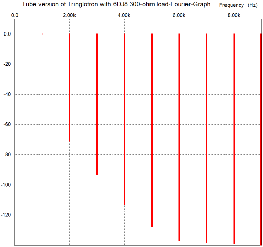
Not too bad, considering the brutally-low 300-ohm load. The distortion is about 1% and the output impedance is about 90 ohms. The Tringlotron, in comparison, makes available the following graph with the same peak voltage swing into 300 ohms.
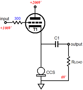
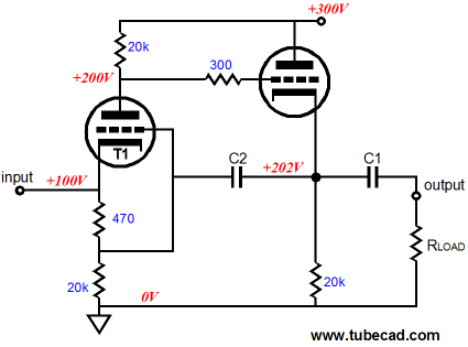
This time, the distortion is less than 0.1% and the output impedance is a low 3 ohms. In other words, this crazy looking circuit delivers the goods. If it hadn't, then moving on to explain how it works would prove much less compelling, as few are as theoretically inclined as I am. In other words, even if this circuit did not outperform the simple cathode follower, I would still be madly interested in how it works. Most solder-slingers think primarily, if not exclusively, in terms of voltage; because the current swings are relatively bigger than the voltage swings in the Tringlotron, it is better to think in terms of current this time; the best would be to think equally in terms of both voltage and current. With peak voltage swings of 1V into the 300-ohm load, we know the load experiences peak current swings of 1/300, or 3.33mA. The top triode, T2, draws a nearly constant current of 10mA, with swings of variation of only 30nA; yes, nano amperes, an electrical current equal to 10 to the negative 9. The middle and bottom triodes, T1 & T3, see equal current swings of 33.36mA, which are in inverted phase to the input and output voltage swings. In other words, as the input signal swings positively at the middle triode's grid, the middle and bottom triodes conduct less current, not more! It is as if the simple cathode follower operation has been stood on its head. Where a simple cathode follower can only deliver negative current swings equal to its idle current, the Tringlotron can only deliver positive current swings equal to its idle current. Where a simple cathode follower can only deliver greater positive current swings than its idle current, the Tringlotron can deliver negative current swings greater than its idle current. Looking at the voltage relationships within the circuit reveals that the top triode's cathode undergoes a peak voltage swing of 1.35V; the middle triode's cathode swings 1.395Vpk; and bottom triode's cathode moves 0.35Vpk, which subtracted from the top triode's cathode's movement yields the 1Vpk into the 300-ohm load. Okay, I'll admit that I am sure that many are more confused than when they first saw the topology. Let it sink in for a day or two, then come back to review it. Does this topology have any progenitors? I know I immediately thought of Sandman's class-S topology and of Charles A. Wilkins US Patent number: 3,184,687, but neither appears to be a likely parent or inspiration. Here is a crazy story. While reviewing the Fourier plots for the Tringlotron, I beheld an intense déjà vu sight, except that it wasn't an illusion; I had seen the same Fourier plot before. The following circuit is something that I came up with long, long ago; in fact, I cannot remember if I have covered it here before. (My goal was to find a good use for dissimilar triodes, such as the 12DW7, with the high-mu triode as input and the low-mu triode driving the load.)
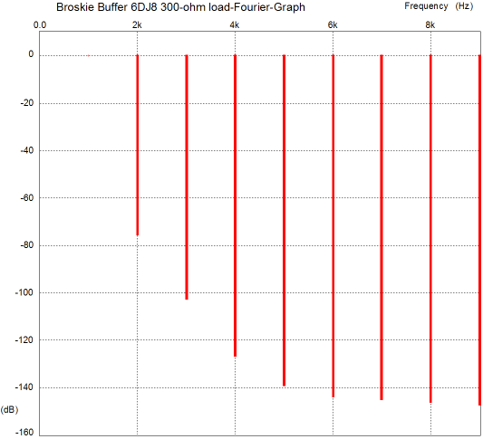
I do not know if I am the first to have come up with it, but is nonetheless interesting. Like the Tringlotron, it simply does not look as if it can work. The input signal is given to the T1's cathode, not its grid, which would seem to imply a crushingly low input impedance, but with a 6DJ8, the impedance is a relatively high 10k. Capacitor C2 bootstraps the input tube, so the input triode's cathode follows the input signal. This capacitor also creates a negative feedback loop through the input tube's grid, so any perturbation at the buffer's output will be entirely relayed to the input tube, which will react by swinging its plate in the opposite direction to the imposed variation in cathode voltage on the output tube's cathode. Here is the Fourier graph for a 6DJ8-based circuit with 1Vpk into 300 ohms @ 1kHz.
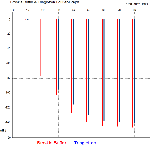
Superimposing both sets of plot lines yields the following graph.
As Danny Devito said to Arnold Schwarzenegger upon meeting him for the first time in the movie Twins, "The moment I sat down I thought I was looking into a mirror." Or as they say in government work, close enough. But what about the output impedance, how do they differ? They don’t; well, not by much. My circuit presents an output impedance of 2.8 ohms, versus the 3 ohms from the Tringlotron. But in terms of PSRR, the tables turn in my favor, as my buffer delivers a respectable -46dB, whereas the Tringlotron musters only -29.9dB, which still respectable.
Next Time //JRB |
E-mail from GlassWare Customers
High-quality, double-sided, extra thick, 2-oz traces, plated-through holes, dual sets of resistor pads and pads for two coupling capacitors. Stereo and mono, octal and 9-pin printed circuit boards available.  Aikido PCBs for as little as $24 http://glass-ware.stores.yahoo.net/
Support the Tube CAD Journal & get an extremely powerful push-pull tube-amplifier simulator for TCJ Push-Pull Calculator
TCJ PPC Version 2 Improvements Rebuilt simulation engine *User definable
Download or CD ROM For more information, please visit our Web site : To purchase, please visit our Yahoo Store: |
|||


| www.tubecad.com Copyright © 1999-2010 GlassWare All Rights Reserved |