| John Broskie's Guide to Tube Circuit Analysis & Design |
|
Post 222 26 December 2011
Happy Boxing Day. I hope your stocking was filled with NOS RCA 2A3, Sylvania 1940s 6SN7 and 1950s Tungsol 5687 tubes. On the other hand, if you, like me, found more coal than NOS tubes in your stocking, then there is still hope. The following new items should go far in erasing some of the gloom left by boring presents. Blog number 221 was updated on December 16th, after Chris Paul came to the mathematical rescue, providing the missing formula.
A-5 Stereo Stepped Attenuator
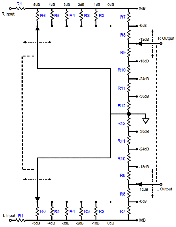
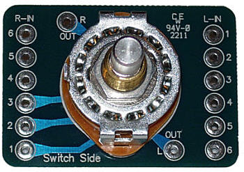
Had the attenuator been a typical series attenuator design, the attenuator would require a 2-pole, 36-position rotary switch and 72 resistors; a purely ladder design, a 4-pol, 36-position rotary switch and 140 resistors. Can you imagine how much either attenuator would cost? In contrast, the A5 attenuator, from 0dB to -5dB steps of attenuation, is solely a shunt attenuator, with no more than one series resistor in the signal path; thereafter, the attenuator uses both a shunt and series configurations, with never more than 7 resistors in the signal path. Also in sharp contrast, the A5 attenuator only cost $24 with resistors, $19 without resistors. So, with even $3 each, super-audio-grade resistors, the total cost would still be less than $100.
Shown above is the A5 attenuator with 1% metal-film resistors. My own preference is to use 1W carbon-film resistors. Speaking of carbon-film resistors, in an AKM Tech Tips PDF that explains how to get the most out their DACs, Basic Layout Tips Part 2: Bypassing and Passive Components, the following is found:
Interesting, no? You can choose between better sonics or better specs. Five years ago, I belonged to the group that thought carbon-film resistors were both cheap and inferior to metal-film resistors; now, I am an apostate that warmly embraces carbon-film resistors. I was not intellectually swayed from metal-film; instead, I conducted my own blind listening tests and my ears convinced me. Believe me, I didn't want to give up my long-held prejudice against carbon-film resistors; I had to be beaten hard about my ears to let go. Well, I am glad I did.
One conceptual problem I faced was that about 30 years ago I held a sonic shootout between the two film types and that the clear winner was metal-film. My best guess as to why carbon lost that time was that the carbon-film resistors at that time were not as tightly on value as they are today, which resulted in imbalances between channels, giving the 1% metal-film resistors an advantage. Today, even nominally 5% carbon-film resistors actually measure much tighter, closer to 2%. In fact, 1% carbon-film resistors can be bought. As for carbon-film resistors being cheap, think again; the 1W carbon-film resistors that come with all the GlassWare kits are twice as expensive as the metal-film resistors. For more on this topic, see my blog 134, under the section titled: Carbon-Film Resistors? The A5 stereo stepped attenuator combines both series and shunt stepped attenuators into a single functional attenuator. The shunt attenuator's job is to provide six fine steps of attenuation, each step being -1dB (or -2dB); the series attenuator, six coarse steps of attenuation, each step being -6dB (or -12dB). The result is that 36 attenuation settings are possible. In other words, we can set the attenuation to any value from 0dB to -35dB in -1dB decrements (or from 0dB to -70dB in -2dB decrements). The shunt attenuator portion of the A5 takes account of its series attenuator's load impedance in the calculation of its resistor values.
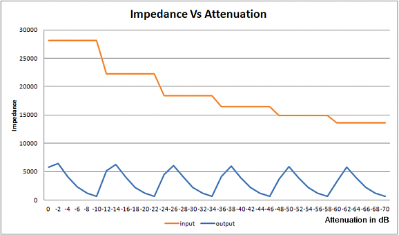
The A5 attenuator's output impedance varies with the amount of attenuation, just as it does with a conventional volume control potentiometer. But unlike a potentiometer, its input impedance also varies with changes in the fine attenuator position.
The input impedance starts from a high of 28k and falls to a low about 14k; the output impedance falls below 7k at all steps of attenuation. The assumption behind this stepped attenuator is that all the signal source will be a modern design, with the ability to drive a 14k load. Of course, the nominal input impedance can be raised to just about any value by using different resistor values. (I plan on using an A5 stepped attenuator—with -1dB & -6dB steps and carbon-film resistors —with a 6SN7-based ACF-2 and a Logitech Squeezebox receiver as the only signal source.)
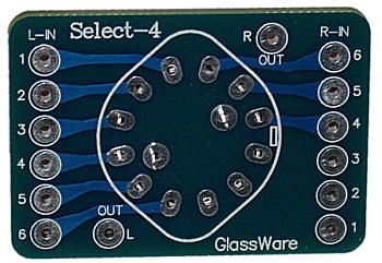
Select-4 Here is a quick way to improve the sound of your system: disconnect all the signal sources, such as CD players, DACs, tuners, tape players, TVs... from the line stage amplifier, but leave them all plugged into the wall and turned on, including the line stage. Now measure the both the AC and DC voltage on the signal source's ground relative to the line stage's ground. If the voltage reads anything above 0V, try flipping the signal source's power plug at the wall socket (you might need a cheater plug). Strive to get the lowest voltage possible. (With old tube equipment, you might be startled to read crazy high voltage differences, as some old gear makes a ground connection to one of the AC plug connections. And if the signal source uses a three-prong power plug, you really don't have an option.) Now, reconnect all the signal sources and listen.
On the other hand, most audio gear is wired with all the input and output RCA jack grounds tied together at the rear panel by a long strip of bus wire. In other words, you don't get to choose how to handle the ground connections, as the decision has been made for you. In such a setup, the following selector switch can come in handy, as it only switches right and left channel hots. Moreover, the Select-4 allows up to six input signal sources to be used.
Of course, the Select-4 could be used a single channel selector switch in a balanced line stage.
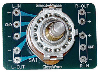
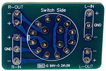
Select-Phase Switch
Wait a minute, the phase is correct on my system, so why would I need to flip the phase? Your system may be in phase (whatever that might mean), but the recorded music that you listen to need not abide to any fixed phase. Indeed, on the album, you can expect that some tracks are in phase and some out of phase. I have been told that recording studios know that phase makes a difference, so they purposely alternate the phase on tracks, so 50% of the time its right. ultimately, we need a computer-based media system that keeps track of the preferred phase for each track. The Select-Phase switch has mute at the center in between phases. In addition, I like being able to park the output at mute, when I power done the piece of equipment and at startup, until the tubes get hot and are up and running.
This switch is also useful for ES headphone amplifier outputs, so the phase can be selected at the outputs. Another use is in the following circuit.
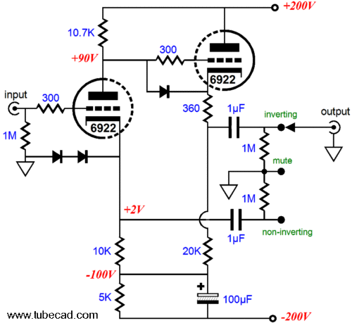
This circuit is a No-Gain-No-Pain type that offers no voltage gain, but with the extra feature of being able to chose the output phase. Each phase output must be used individually and separately; in other words, no balanced out. The output impedance is equal from each out, but only when one output phase is used. The diodes can be just about any type, such as a 1N4007 or 1N4148; they only conduct at startup, when the triodes are cold, but they prevent the triodes from having their grids be insanely positive relative to their cathode at startup, for example +400Vdc. For those who need some voltage gain, the following variation could work well, if and only if...
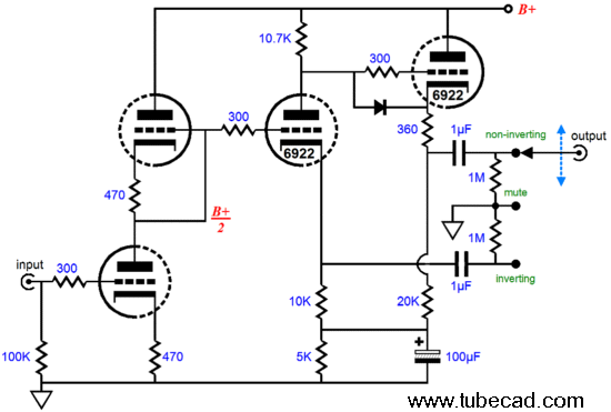
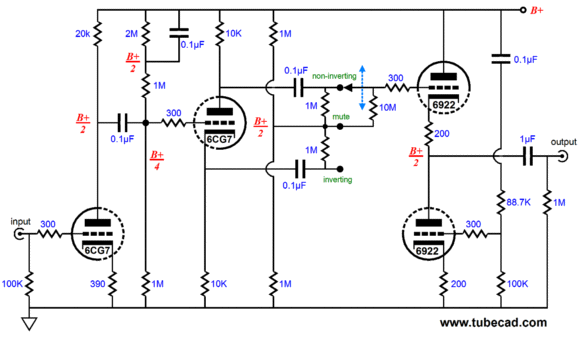
Note that this version does not, in Aikido fashion, null the power-supply noise at the output, as the no-gain version does; instead, it offers a PSRR of only -6dB, from each phase output, so the power supply must be well-filtered or regulated. A 12AU7 or 6CG7 or another 6922 could be used as the input tube and a B+ voltage between 200Vdc to 300Vdc would work well, although I am a bit nervous about the topmost cathode follower seeing too high a cathode-to-heater voltage. The following circuit makes use of an Aikido cathode follower, which provides both a low output impedance and a stellar PSRR. The B+ voltage can span from 150Vdc to 250Vdc and a 6CG7 could be used as the output tube in the Aikido cathode follower stage. The heater power supply should be referenced to one quarter of the B+ voltage.
The circuit circuit needs a name, so how about the "Aikido Diametrical line stage amplifier." (The "Aikido Dichotomy" is also a cool name, but the "Aikido Dicephalous" is a bit too pedantic, besides this line stage offers only one output stage per channel.) The Aikido Diametrical works in an interesting fashion: the grounded-cathode input stage presents a PSRR of -6dB, which means that 50% of the power-supply noise is superimposed on its output signal. The split-load phase splitter then delivers two phases of this signal, each with 50% of the power-supply noise is superimposed in phase. The Aikido cathode follower stage anticipates the 50% of the power-supply noise ridding on each phase and applies an opposing power-supply-noise-induced current variations that null the noise from the output signal. Before anyone asks, of course other tubes could be used, such as 6SN7, 12BH7, ECC99, 5687 tubes. And a second Aikido cathode follower output stage could be added, allowing a balanced output; in this setup, the Select Phase switch could appear after the 1µF output coupling capacitors. (With two Aikido cathode follower output stages per channel, the name "Aikido Dicephalous" might be worth looking into again ;)
Next Time
//JRB |
|
I know that some readers wish to avoid Patreon, so here is a PayPal button instead. Thanks.
John Broskie
E-mail from GlassWare customers:
And
High-quality, double-sided, extra thick, 2-oz traces, plated-through holes, dual sets of resistor pads and pads for two coupling capacitors. Stereo and mono, octal and 9-pin printed circuit boards available. Aikido PCBs for as little as $20.40 http://glass-ware.stores.yahoo.net/ Only $12.95 TCJ My-Stock DB
Version 2 Improvements *User definable Download or CD ROM www.glass-ware.com |
||
| www.tubecad.com Copyright © 1999-2011 GlassWare All Rights Reserved |
