| John Broskie's Guide to Tube Circuit Analysis & Design |
| Post 221 10 December 2011
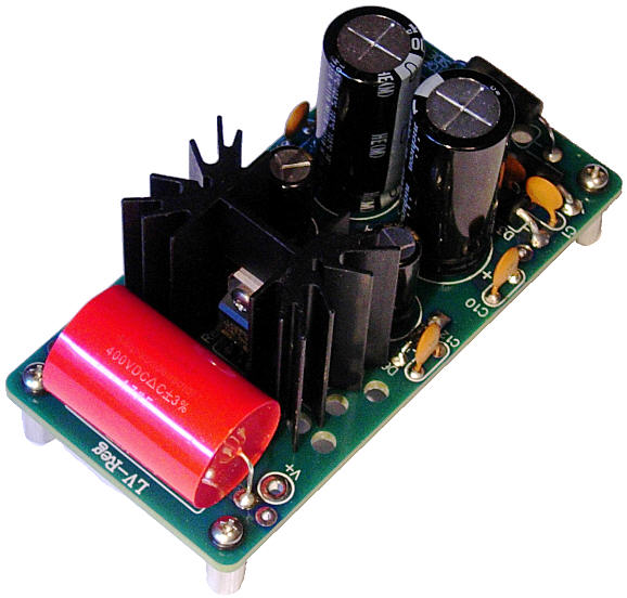
New LV-Regulator The LV-Regulator uses a simple RC filter (1 ohm & 10kµF) as a pre-filter before the LDO regulator and holds bypass capacitors for all the electrolytic capacitors and a 4.7µF/400V polypropylene shunting capacitor at the output. The LV-Regulator can be set up as either a 5Vdc or 9Vdc regulator (or as a 12Vdc, if you want). It uses a 3A low-dropout regulator (LD1085) and two resistors set the output voltage value. The 1-ohm resistor is a 4W device, so the maximum current output is 2A. My habit has been to always place such an RC filter before my voltage regulators, as I want to unburden the regulator from having to deal with sharp transients. But you have to be willing to pay a price for the RC filter, as even a 1-ohm resistor will displace a lot of voltage, when the regulator must put out 3A, as it might when the load is a heater, which is why I left an RC filter off the H-PS-1 regulator. The LV-Regulator board is bigger than the H-PS-1 board and it cannot accept the voltage-doubler rectifier configuration, which the H-PS-1 can. But the NEW PCB does accepts two possible rectifier configurations (full-wave bridge and full-wave center-tapped). In other words, this regulator can deliver +5Vdc or +9Vdc from two different power transformer secondary voltages; for example, for 9V output either a 10Vac or 20Vac CT transformer secondary (10V-0-10V); or 5Vdc from either a 6.3Vac to 9Vac or a 12Vac to 18Vac center-tap secondary. When used as a full-wave-bridge rectifier circuit, all four rectifiers are used. But when configured in a full-wave center-tapped configuration, only rectifiers D2 and D4 are used; attach the transformer secondary center-tap to bottom solder eyelet for rectifier D3, the one that attaches to ground. The main advantage behind using a center-tapped power transformer is that the rectification of AC into DC only loses one rectifier voltage drop, rather than the usual two drops: a 0.7V versus a 1.4V voltage drop can make a decisive difference in a low-voltage regulated power supply, such as a 5V regulator. At idle, without an external load, the regulator draws 10mA of current. The board is 4.5in by 2.2in (114mm by 56mm), with four mounting holes. The kit includes all the parts, diodes, ultra-fast rectifiers, Nichicon and Panasonic capacitors, resistors, 4.7µF polypropylene output capacitor, LDO regulator, heatsink and heatsink mounting kit, including four aluminum hex standoffs, rubber O-rings, and eight screws. Best of all, it costs only $29. The H-PS-1 hasn't been replaced, as it is still available; it just has a new bigger, more handsome brother.
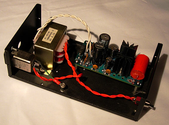
Shown above is a LV-Regulator mounted in a chassis (I have the cover). It's not finished yet, but close. This is the third time I have made this project, albeit with H-PS-1 regulators in the first two versions. Why three times? Once a friend borrows my power supply to try with his Logitech Duet or DAC, I am always talked out of it quickly. Here is a link to the user guide. The LV-Regulator (and the H-PS-1) is available at the GlassWare-Yahoo store.
Dead Quiet
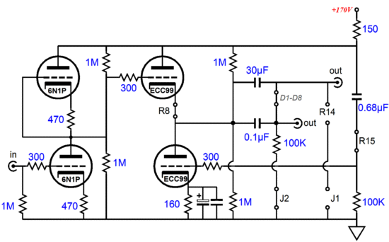
My recommendation to him, if the lowest possible noise was his goal, was to use a 6N1P as the input tube and an ECC99 as the output tube, in a White-cathode-follower configuration. The 6N1P is a Russian dual triode that many confusingly believe to be direct replacement for the 6DJ8/6922/ECC88; it's not. Not even close. Where a 6DJ8, with a 100Vdc plate voltage and -2V grid voltage, will draw about 10mA, the 6N1P draws only about 1mA. Additionally, its heater draws twice the heater current that a 6922 draws. Still the 6N1P is a fine tube. Its best feature is its potential for truly low-noise operation. If you do some culling, you can find an amazingly quiet 6N1P tube. The ECC99 is similar to the 5687 and the Russian 6Н30П, but with the same base pin-out as a 12AU7. I covered this mighty dual triode back in blog number 198. Often labeled a "Super Triode," the ECC99 made by JJ is an excellent choice for an output tube in a headphone amplifier, as it its high transconductance and large cathodes can swing a lot of current into the low-impedance load. (The GlassWare 9-pin mono PCBs can be wired to accept 5687s as the output tube, by the way.)
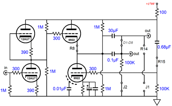
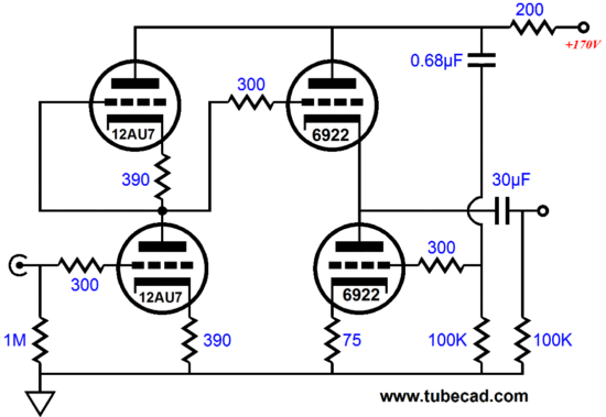
I sent Richard a list of part values and desired voltages, so he was ready to go. But, no go. Why not? His power transformer was nowhere near powerful enough to power the heaters. Configured for a 12.6Vdc heater regulator, the four tubes draw 1.2A, which equals over 20W of heat from both tubes and the heater regulator. Richard tried many different resistor loads on the transformer's heater winding (AC only, no rectification) and he discovered that the winding could probably support half that much current. So, he bought a new power transformer, right? No. He couldn't, as he had high-jacked an existing chassis and the transformer and power supply came with the package, besides it was potted in a great looking metal can. The easiest workaround was simply to use different tubes. My usual recipe is good one: 12AU7 as input tube, 6922 as output tube. The total heater current draw, with a 12.6V heater power supply, is only 0.6A. The 6922 will not last as long as the ECC99, but then it is relatively cheap tube. Furthermore, Richard's 300-ohm headphones only require a peak voltage swing of about 3V, which results in a peak current swing of 10mA; and the White-cathode-follower configuration of the headphone amplifier's output stage allows at least twice that peak current swing, with 6922 output tubes and with an idle current of 13mA. Well, I assumed this tale would here. It didn't.
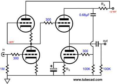
Richard build up his headphone amplifier and was quite pleased with the results, but he wanted to try not using a bypass capacitor on the output stage's lone cathode resistor, which he knew would require recalculating the plate (current sense) resistor's value, as the bottom triode in the White cathode follower would exhibit less transconductance than it had in the resistor-bypassed version. A quick review: the way in which a White cathode follower works is simple enough; the variation in current flow through the sense resistor at the plate creates an anti-phase drive signal for the bottom tube, ensuring proper push-pull operation of the output stage, allowing up to twice the idle current to be delivered as peak current swings into the load. Since the unbypassed cathode resistor effectively halves the bottom triode's transconductance, I just doubled the value of the sense resistor for Richard. (He is using carbon-film resistors and 5% standard resistors greatly limit the resistor values, which is often a blessing in disguise.) So, he was off and running and once again I thought this would be the end of the story. Once again, I was wrong.
He wrote back to tell me that he loved listening to THE finest music reproduction he has heard to date (Richard sings in choir and he uses DAT recordings of him and his fellow singers as test material) and that he loved the now non-measurable power-supply noise at the output. While I am extremely pleased that he likes the sonic improvement, being both relieved and somewhat vindicated, since I sort of talked him into making the changes, I don't actually find his sonic evaluation newsworthy. Why not?
Imagine a that a young groom tells you that his bride is the most beautiful woman in the world. Will you then call the newspapers and TV stations proclaiming that they must immediately send over a camera crew and reporters, as the most-beautiful woman in the world has been found? No, not likely; instead you are happy for your friend, but you wisely keep his news to yourself. Richards second statement, on the other hand, did get my attention. How could that be? How could there be no power-supply noise at the output? Over the last 25 years, I have built tens of White-cathode-follower circuits and none of them ever had a PSRR even close that of an equivalent Aikido cathode follower. No power-supply noise at the output is something that I can test; something I can measure. I cannot listen with Richard's ears or listen to his system or even to his DAT recordings, but I can measure and evaluate a PSRR result. This was news.
I quickly ran some SPICE simulations of the circuit setup I had recommended and I beheld a -54dB PSRR figure. Wow! In other words, with 500mV of power-supply noise on the B+, only 1mV makes it to the output. And considering that the actual B+ power-supply noise might be only few millivolts, we shouldn't be surprised that Richard wasn't able to measure any noise at the headphone terminals, as the noise fell below the threshold of his voltage meter. This is not what I expected, as I expected a PSRR figure closer to -12dB. What went right? It is as if you deposited a check for $100 and the ATM receipt read $6,000 had been deposited. What's more, the values I gave Richard were, I am both embarrassed and proud to say, just quick guesstimates that I performed in my head without a calculator. As a reality check, I asked Richard what the PSRR had been with the old part values and the cathode resistor bypassed. He told me -15dB, which is much closer to what I expected. Once again, what went right? I realized the old formula that worked well with a stock, stand-alone White cathode follower, actually might not be suitable for his Aikido-based headphone amplifier, as I had altered the topology in fundamental way a few years ago. First, here is the old style topology.
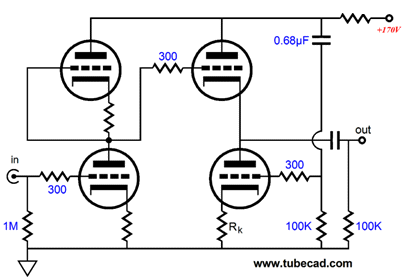
And here is the old formula: Rs = (rp + 2Rload) / mu where Rs is the series current sense resistor at the plate. Now, here is the new topology:
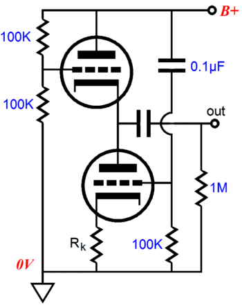
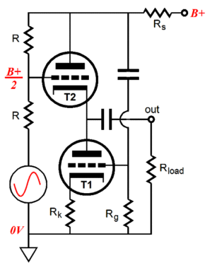
My modification was to make both input and output tubes share the common plate (current-sense) resistor (Rs), which dramatically changes the voltage and current relationships. (Why did I change the mono PCBs to this new topology? I had been experimenting a few years ago and I discovered that this new topological variation produced slightly less distortion, but at the cost of slightly less gain and slightly more power-supply noise at the output, which I felt was a good trade, so I included that change in the new revision of the mono PCB. Well, at least that's what I remember my thinking to be. The flood of circuits that abundantly flow through my mind in week is staggering; by the end of year, the deluge is overwhelming, at least for me, as cannot keep track of all of them.) With both the input and output stages sharing the same current path through the sense resistor, the input stage defines a 50% voltage divider that also superimposes 50% the sense-resistor-created voltage signal that goes into the White cathode follower output stage's top triode's grid. Not so much like a snake biting his tail, but his belly. Yes, my head also began to swim. Thus, 100% of the sense-resistor-created signal is delivered to the White cathode follower's bottom triode's grid and 50% to its top triode's grid. As a result, should the sense resistor's value be doubled? Or halved? Or some non obvious ratio? Or left alone? At one point it all seemed to instantly make sense: because the two-tube voltage divider returned half the signal from the sense resistor to the top triode's grid, the load impedance was now effectively 1.5 times greater, as a the sense resistor only saw a 66% change in current that we would expect for the load resistance, but everything else should remain the same I thought. A few days later, I tried mathematically evaluating my reasoning, but the clarity that so impressed me a few days earlier had now vanished, as the math did not add up. Yet, the result seemed to work fairly well, as plugging an Rload of 450 ohms (1.5 x 300) into Rs = (rp + [mu + 1]Rk + 2Rload) / mu gave the answer (Rs = 203) close to what I recommended that Richard use (Rs = 200 ohms). Well, 99% of you may be happy—indeed, overjoyed—not to see a sound mathematical proof, but I and the 1% are less happy. (I am going to have to get Chris Paul to look into this, as mathematical analysis is what Chris does best.) In the mean time between discovering this magic set of part values and figuring out the exact formulas that explains their values, we can steal these results, no matter what their source, whether it be subconscious inspiration or just luck; as they say, nothing succeeds likes success. The following formula, which comes from blog number 13, is a good starting point. Rk = rp(mu -2) / (mu² + 3mu + 2) It gives us the optimal value for the bottom cathode resistor in an Aikido cathode follower that lacks a top cathode resistor and that returns all the of power-supply noise to the bottom triode's grid.
The logic is simple enough, even if the formula for the above circuit isn't. The two 100k resistors in series represent the two input triodes of an Aikido amplifier, as they, too, 50% voltage divide both the AC and DC voltages. Thus, half of the power-supply noise is presented to the top triode's grid and all the power-supply noise is presented to the bottom triode's grid. The only way we can arrive a t a noise null at the output is for the bottom triode to vary it conduction just enough to counter the 50% of power-supply noise the top triode sees at its grid and the 100% it sees at its plate. Roughly, the cathode resistor should equal about 1/gm, but the above formula gives a more exact result. If we do the math, we see that the optimal value for a 6922 tube with B+ of 170Vdc (roughly 85Vc across each triode) is about 75 ohms. (I am using the rp and mu from the SPICE triode model, not the datasheet. Which means that Richard, who lives in the real world, could probably squeeze a few more dB of PSRR enhancement out of his tube headphone amplifier, with some small part value fiddling. His real 6Dj8 will no doubt neither exactly match the SPICE model nor the tube manual's values.) IMPORTANT. Bear in mind two things: if you are not driving brutally-low impedances, you do not need this circuit, as the output stage is fundamentally a push-pull topology that can deliver twice the idle current into the load; second, only the Aikido mono PCBs (both the octal and 9-pin) and the 9-pin Aikido LSA/HPA boards use this modified topology. Next time I order a run of PCBs, however, I will make this topological change to all the other Aikido PCBs. Although if you are any sort of hacker (remember when being a labeled a hacker was good), you would have no problem cutting two PCB traces and soldering in place a short jumper wire. If you are not a born hacker, then you would probably sooner travel to the Moon to pick up some rocks than consider such an undertaking.
Chris Paul to the Rescue (update Dec 16 2011) Chris Paul quickly—amazingly quickly—produced the actual formula, which is both complex and accurate. I know many will be scared by its complexity. But as much of life is both complex and inaccurate, we should rejoice when we encounter something that is both complex and accurate. And as tempting as that which is both simple and accurate can be, we should be willing to let go of this ideal when it is unattainable.
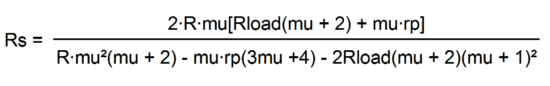
The first step is to find the cathode resistor's value for the output stage, which will ensure the deepest null in power-supply noise at the output: Rk = rp(mu -2) / (mu² + 3mu + 2) The second step is to find the resistance R, which is the effective resistance of one of the input stage's triodes and its unbypassed cathode resistor, not the output stage cathode resistor: R = rp + (mu + 1)Rk The third step is to plug R into Chris Paul's formula:
Bear in mind that the resistor Rs is in parallel with the bottom triode's grid resistor. If Rg/Rs is more than 100, we can pretty much ignore Rg, as most resistors seldom are better than 1% accurate. In fact, I am a big fan of practical, simplified formulas, as the trap of excessive (or false) precision is an easy one to fall in. How closely matched do you imagine the two triodes are the dual-triode tube? How close does the tube manual's specified mu, rp, and gm actually come to a triode's actual attributes? I get nervous e-mails that bemoan a measured 197Vdc, when the formula dictated 200Vdc as the operating point in a complex tube-filled circuit. Do you know how satisfied a designer of solid-state gear would be to encounter 98.5% prediction attainment, in the absence of 100dB of negative feedback? And what can be sillier than hunting for a 58.3482k resistor, which implies that such impossibly tight-tolerance resistors in fact exist? They don't, so go for the 59k resistor and stop worrying.
Next Time
//JRB |
I know that some readers wish to avoid Patreon, so here is a PayPal button instead. Thanks.
John Broskie
E-mail from GlassWare Customers
High-quality, double-sided, extra thick, 2-oz traces, plated-through holes, dual sets of resistor pads and pads for two coupling capacitors. Stereo and mono, octal and 9-pin printed circuit boards available.  Aikido PCBs for as little as $24 http://glass-ware.stores.yahoo.net/
Support the Tube CAD Journal & get an extremely powerful push-pull tube-amplifier simulator for TCJ Push-Pull Calculator
TCJ PPC Version 2 Improvements Rebuilt simulation engine *User definable
Download or CD ROM For more information, please visit our Web site : To purchase, please visit our Yahoo Store: |
|||


| www.tubecad.com Copyright © 1999-2011 GlassWare All Rights Reserved |