| John Broskie's Guide to Tube Circuit Analysis & Design |
Post 249 13 November 2012
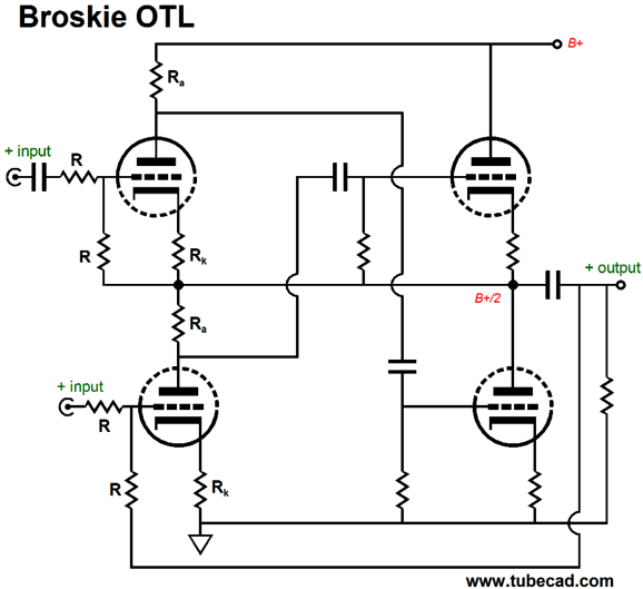
Broskie OTL
Well, many readers asked, What heck is a Broskie OTL? It is an OTL amplifier topology that I came up with that accepts a balanced input signal and delivers an unbalanced output signal with very low distortion and low output impedance. Blog post numbers, 193, 194, 196, and 239 give the details.
The surprising thing is how now, six years later, this topology is being discovered by many long-time TCJ readers. This reminds of a passage from Nietzsche's book, The Gay Science.
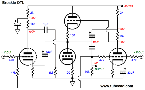
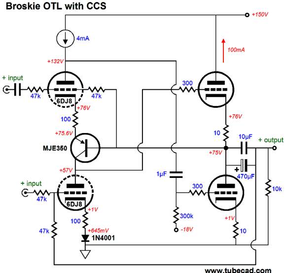
No doubt for many readers, the mentioning of the madman is the only part that seems appropriate to this blog post. Well, I have dug out my notes on the Broskie OTL, which is directly related to the Broskie CF, and found some interesting stuff. For example, the following variation takes the two driver triodes and gives them twice as large a voltage envelope to operate within.
If you compare schematics—the above variation of the Broskie OTL to the Broskie OTL above it—the obvious difference is that the driver triodes no longer stand atop each other, so each triode gets access to the full ground-to-B+ voltage, not just half of it. Why is more voltage an advantage? More voltage means that larger-valued plate resistors can be used, which will garner more gain; and the triode can undergo greater plate-voltage swings, which means that low-mu triodes, such as the 6AS7 or 6C33 or 12B4 can be used as the output tubes. Moreover, the extra voltage allows to incorporate an RC power-supply-noise filter for the positive-input triode on the left, which helps improve the PSRR of the OTL. Note how both driver triode cathode resistors are bypassed by a 33µF capacitor, with the capacitor on the left being terminated into the output; and the one on the right, into ground. In other words, both driver triodes will realize the same open-loop gain, as both work into the same valued plate resistor. Also note the directly coupling of the top output triode's grid to the rightmost triode's plate. Direct-coupling can be a beautiful thing, as it eliminates phase shifts, but it can also incur headaches, if the driver tube is missing from its socket for example; thus, the safer approach is to add an additional coupling capacitor. I left out of this schematic the essential grid-stopper resistors for the output tubes, just to make the naked topology clearer. Okay, now that we have warmed up, fasten your seat belt and let's move on to the next variation on the Broskie OTL.
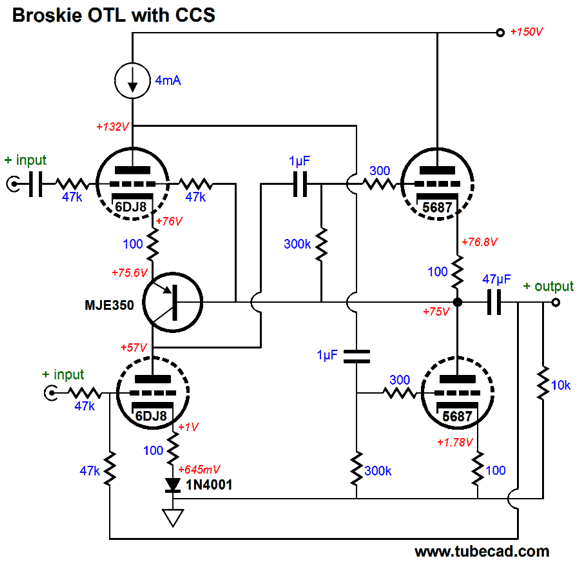
Broskie OTL & CCSs
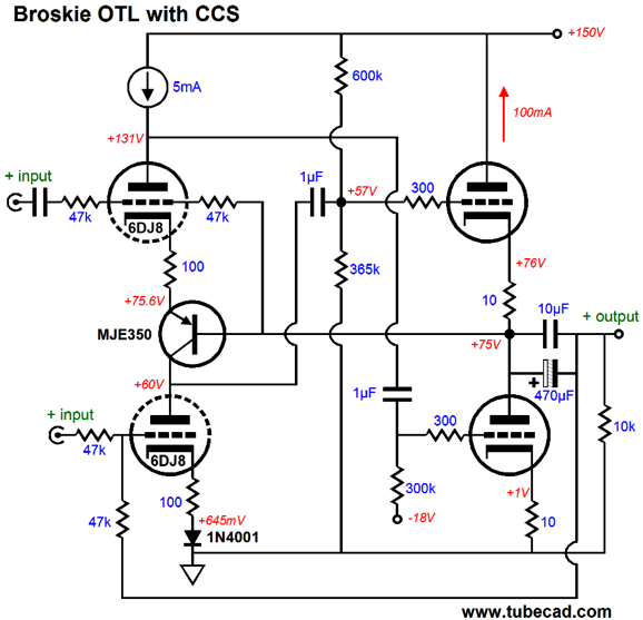
The two constant-current sources not only allow both driver triodes to achieve their maximum gain (the mu of the triode used), they substantially improve the OTL's PSRR, shielding the circuit from the power-supply noise. A constant-current source can be amde from high-voltage FETs or depletion-mode MOSFETs or transistors. The following circuit creates the bottom constant-current source from a single PNP transistor.
Try to ignore all the part values and focus on the PNP transistor. It relays the output signal to the top input triode and it functions as a constant-current source for the bottom input triode. Because of the transistor's base-to-emitter voltage drop (about 0.6V), a complementery voltage drop must be included for the bottom triode, which the 1N4001 rectifier provides. The output triodes use cathode resistors to set the idle current through the output stage. If a low-mu triode, such as the 6AS7, is used, then its cathode resistors will prove far too large in value, wasting heat and excessively increasing the output impedance. The workaround is to use fix bias instead.
A negative power-supply rail will be needed, which many readers will not like, but -18V can easily be derived from two 9V batteries in series. Note the direct coupling of the top output triode's grid. Once again, the problem that might arrise is the failure of the output stage to center at half the B+ voltage. The better aproach might be to use two internal couping capacitors.
Note the changes in plate voltage for the two driver triodes, which I included to show imbalances due to variations in a poorly matched triodes within a 6DJ8 tube. Why are there 10-ohm cathode resistors if fixed bias is used? These are safety resistors, which can act as fuses and help prevent the output tube from going into a current runaway situation, as the resistors provide some degenerative feedback. Also note the 470µF output capacitor. Why so large a value? The design goal for the above circuit was to make unity-gain, high-current, unbalanced-to-balanced power buffer to drive 50-ohm headphones. My thinking was that many DACs come with XLR balanced outputs that are seldom used. And since many control the volume with their computers, this otherwise wasted balanced output could be put to use driving the above circuit, which, in turn, would drive the fancy, new, planer headphones. The assumption was that a 6AS7 or 6080 or 6082 dual triode would be used as the output tube. Of course, a different tube or tubes could be used, such as the 6BL7, 6BX7, 6C33, 6H30, 6SN7, 12B4, 5687, ECC99, 300B, and a triode-connected EL86 might be the best choice. An idle current of 100mA, means a potential output voltage swing (still within the class-A envelope) of 10Vpk is possible (200mA against 50 ohms), which should be plenty, even for the least efficient headphones. (Unfortunately, most DACs do not put out such a hot signal, so a balanced line stage would be needed.)
Current-Mirror-Based Push-Pull Buffer
and this one
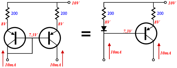
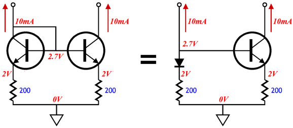
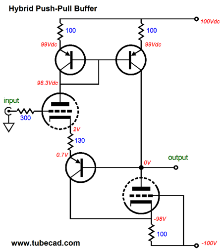
Why? Apparently, the images helped these two readers finally grok* how the current mirror based on two transistors worked. Great, welcome aboard. The following circuit uses a current mirror and two triodes to create a push-pull, unity-gain buffer.
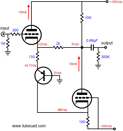
I am sure that I have shown this topology before in a post on tube OpAmps, but I cannot find it. The closest that I could find was this schematic from 2008's blog 148.
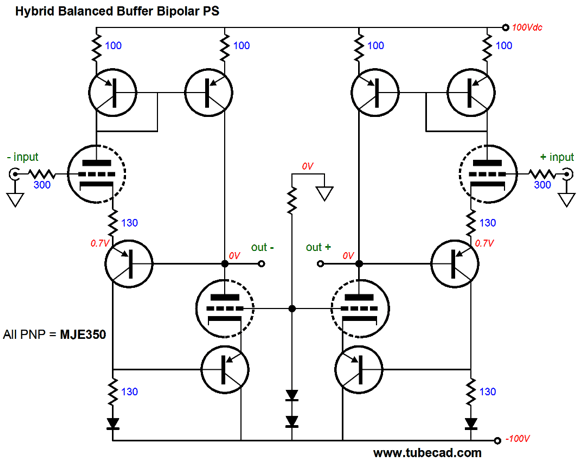
The above circuit is an amplifier, not a buffer, due to the inclusion of the 2k resistor; furthermore, this circuit uses a single-ended output stage. Returning to the push-pull version with the current mirror, in what application could this buffer be used? Just about any that requires an low-impedance buffer. But what I was thinking that would prove interesting would be a balanced version that could drive 250-300 ohm headphones, such as those made by Beyer and Sennheiser.
Yes, I know that it appears insanely more complex, but actually it is a very simple circuit. The bottom-most PNP transistors drive the output triode cathodes with effectively an inverted signal relative to the input triodes. The result is push-pull action. The two diodes in series are there to create a simple 1.4V voltage reference for biasing the output triodes. No output coupling capacitor is shown, but I would use one nonetheless; a single 30µF film capacitor would work and grant me some piece of mind. Of course, an output transformer could be used instead.
Next Time
* Excerpted from American Heritage Talking Dictionary
//JRB |
I know that some readers wish to avoid Patreon, so here is a PayPal button instead. Thanks.
John Broskie
The Tube CAD Journal's first companion program, TCJ Filter Design lets you design a filter or crossover (passive, OpAmp or tube) without having to check out thick textbooks from the library and without having to breakout the scientific calculator. This program's goal is to provide a quick and easy display not only of the frequency response, but also of the resistor and capacitor values for a passive and active filters and crossovers. TCJ Filter Design is easy to use, but not lightweight, holding over 60 different filter topologies and up to four filter alignments: While the program's main concern is active filters, solid-state and tube, it also does passive filters. In fact, it can be used to calculate passive crossovers for use with speakers by entering 8 ohms as the terminating resistance. Click on the image below to see the full screen capture.
Tube crossovers are a major part of this program; both buffered and un-buffered tube based filters along with mono-polar and bipolar power supply topologies are covered. Available on a CD-ROM and a downloadable version (4 Megabytes). |
|||


| www.tubecad.com Copyright © 1999-2012 GlassWare All Rights Reserved |