| John Broskie's Guide to Tube Circuit Analysis & Design |
18 February 2013
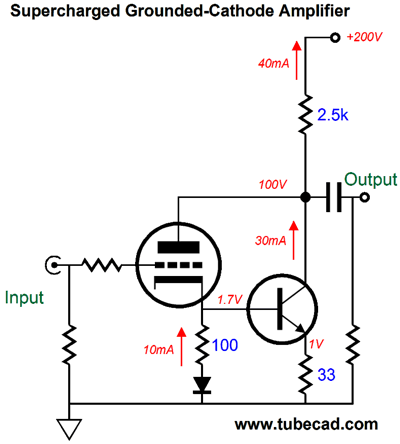
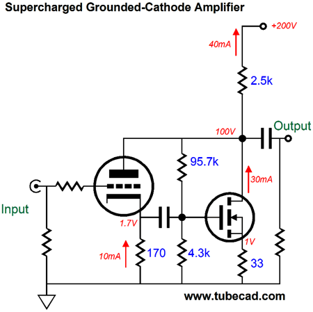
Solid-State Superchargers My prejudice is in favor of the supercharger. Why? I don't like how a turbocharger’s boost is based on the engine's RPM cubed, whereas the supercharger boost is based on the RPM squared. In other words, the turbocharger has an all-or-nothing quality, whereas the supercharger offers a smoother transition into increased horsepower. Ideally, a bigger engine is best, were it not for the increased weight and cost. Great, but what does this have to do with tube circuits? My answer is that tubes are at a distinct disadvantage when trying to deliver lots of current directly into low-impedance loads, such as headphone and loudspeaker drivers. Tubes are high-voltage, low-current devices that are ill-suited to delivering high-current at low voltages, which is why most tube-based power amplifiers use an output transformer. In contrast, a single power transistor or MOSFET can, with only a 10V power supply, deliver 20A of current. Thus, if we wish to forgo the output transformer and directly drive an 8-ohm load, our only recourse is to place many high-current tubes in parallel. Or is it? My idea is that we can use a solid-state device as an electronic current booster of sorts, which would augment the tube's puny current flow with a robust torrent of current from the power transistor or MOSFET. In other words, a solid-state supercharger. The following is an example, a simple supercharged grounded-cathode amplifier.
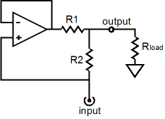
By itself, the triode could not work into the 2,500-ohm plate resistor, as it cannot draw that much current with only 100V from its cathode to its plate. But with the aid given by the transistor, which must draw three times the current the triode conducts, a total of 40mA of current flows through the plate resistor. Why must the transistor draw three times more current than the triode does? Since the transistor's emitter resistor is one third the ohmage of the triode's cathode resistor and since both resistors see the same voltage drop (at all times), the transistor will always conduct three times as much current as the triode (exempting complete cutoff of both devices, of course). The diode below the cathode resistor ensures that the transistor's base-to-emitter voltage drop does not skew the ratio of conduction, as its voltage drop matches that of the transistor. Thus, if the transistor's emitter resistor were only 10-ohms, not 33 ohms, then the transistor would draw ten times more current than the triode; and if its emitter resistor were 100 ohms, then it would conduct equally with the triode. Imagine that the tube held a metal base, in which the power transistor was both attached to the triode and hidden from sight. Such a hybrid device would function so much like a triode, albeit with extraordinarily low rp and high transconductance, that few would suspect that the transistor was there. Indeed, this hybrid device would trace characteristically triode-like plate curves. In other words, the triode is in charge, not the transistor, even though the transistor is doing three times more work than the triode. If the triode and transistor were wired up in parallel, this would not be true; but as the devices cascade from triode to transistor, the triode gives the orders. Speaking of rp and transconductance, what is the effective rp and gm of this hybrid pairing? Because both the cathode resistor and emitter resistors are unbypassed by a large-valued capacitor, the math get slightly thicker than just the rp/4 and 4gm that you might expect. The effective rp (rp with an " ' " means effective rp) is equal to rp' = (rp + (mu + 1)Rk) / 4 And the effective gm, gm’, is equal to gm' = 4mu / (rp + (mu + 1)Rk) In both these formulas, the number 4 appears, as it is the result of dividing the cathode resistor's value by the emitter resistor's value and then adding 1; or, Ratio = Rk/Re + 1. This ratio is also useful in working out the load the triodes see. The triode and its cathode resistor and supercharging transistor and its emitter resistor define an impedance multiplier circuit (IMC). (See IMC Baby Steps for more details on this concept.) Where the triode's cathode resistor equals R2 and input is the triode's cathode; the transistor equals the unity-gain buffer and its emitter resistor is R1.
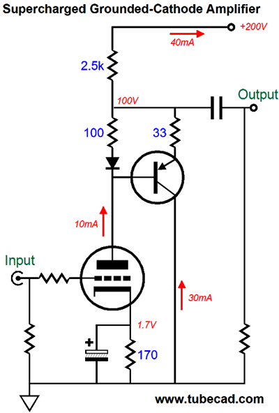
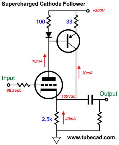
So, the effective load the triodes see is equal to Rload' = Rload(R2/R1 + 1) + R2 While the output stage is operating within its class-A window of current flow, the effective load is twice as large; but once class-B operation is entered, the load falls to Rload'. So, what is the effective mu, the amplification factor of this hybrid device? The mu attribute is a derived one that denotes the transconductance multiplied against the plate resistance, mu = gm • rp. It is a measure of the effectiveness of the grid over the plate in controlling current flow through the triode. If we multiply the two previous formulas against each other, the result is still mu. In other words, the amplification factor remains unchanged. As I said earlier, the triode is in charge of the transistor. Now that we have done our warm-ups, we can look into making a supercharged grounded-cathode amplifier with a PNP transistor.
This time the transistor’s emitter resistor is 1/3 as large as the triode’s plate resistor. Nonetheless, the same supercharging enhancement obtains. In fact, this time we can realize more gain from the hybrid pairing, as the triode’s cathode resistor can be bypassed, as it is in this example. Could we use a MOSFET in the transistor’s stead? We could, but unlike the transistor, MOSFETs do not exhibit a nicely predictable gate-to-source turn-on voltage. In other words, the MOSFET would require much more tweaking of values. In addition, where a power transistor needs about 0.7V of base-to-emitter voltage to begin conducting, a power MOSFET might require 5V to start conducting. That is a lot of voltage and it would require either a very-low-mu triode or a higher B+ voltage to establish a cathode voltage of 5.7V (do not forget the needed diode). One possible workaround is to use a coupling capacitor between the cathode and the MOSFET’s gate, which would allow us to forgo the diode and let the triode find its desired cathode voltage.
In the above schematic, the MOSFET gets a gate voltage of 4.3V, while the triode’s cathode sits at 1.7Vdc. In AC and DC terms, the MOSFET will conduct 170/33 times more current than the triode—about five times more current in other words.
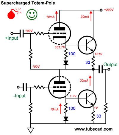
Supercharged Totem-Pole Output Stages
Let’s now look into making a supercharged totem-pole output stage, such as was used in the famous Futterman OTL amplifier.
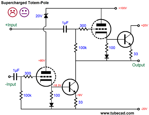
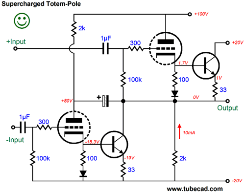
Both top and bottom hybrid sections can be configured as either cathode followers or grounded-cathode amplifiers, depending on how the phase splitter is arranged and connected to the output stage. The happy face denotes the supercharged performance. Indeed, such a setup as shown above could drive very low-impedance loads, such as 50-ohm planer headphones; and by using beefier triodes and many transistors in parallel, 8-ohm speakers could even be driven. The red bomb denotes a lurking danger in this circuit. Here is an example, say we are driving 50-ohm headphones, which require 10Vpk (1W) to really thunder. With the right tube, such as a 5687 or ECC99, the above circuit could readily deliver the required 200mA of current, so what's the problem? The danger is that the power transistor must draw peaks of 150mA with 90V across its emitter and collector. That is a lot of heat, mostly wasted heat. If the B+ voltage had been only 15Vdc, as it would be in a solid-state headphone amplifier, the transistor would run much cooler and be less stressed. One workaround would be to give the transistors their own lower B+ power supply. In the following schematic, we see three power-supply rail voltages: +100V, +20V, and -20V. (The zener diode absorbs the extra 20V that the left triode would otherwise see at its plate.)
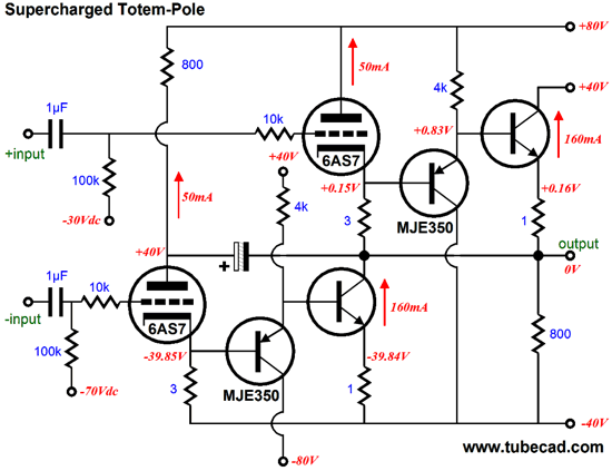
If the above output stage were driving the 50-ohm headphone driver to peaks of 10V, the transistor would only see an emitter-to-collector voltage of 5V at the peaks, which against the 150mA of current creates much less heat. (If the math doesn't’t make sense, it is because you forgot to include the voltage drop across the emitter resistor.) Okay, so why the unhappy face? If you examine the schematic carefully, you will see that the output will not center at 0V, as leftmost triode’s current conduction does not flow into either the external load or into the top triode and its transistor. In other words, the balance is messed up. To achieve true balance, all the triodes and transistors must work together. The following circuit accomplishes a balanced operation by using a large-valued capacitor to couple the left triode’s plate to the load and two 2k resistors to establish the required static current flow, ensuring no DC offset at the output.
A danger remains, however. What happens at start up, when the tubes are cold and not conducting? The external load only sees a 2k resistor that attaches to the -20V power-supply rail. In the case of 50-ohm headphone driver, the drivers will see -0.5Vdc until the tubes warm up. Since the planer headphones are so power hungry, they might survive this offset. But with 300-ohm headphones, the DC offset would grow to 2.6V! The best solution would be either to use a coupling capacitor or headphone protection circuit that would clamp the output to ground until the offset disappears—a voltage window comparator and relay, in other words. Making a version of this circuit strong enough to drive 8-ohm loudspeakers isn't much more difficult, but it does make for a more complex schematic.
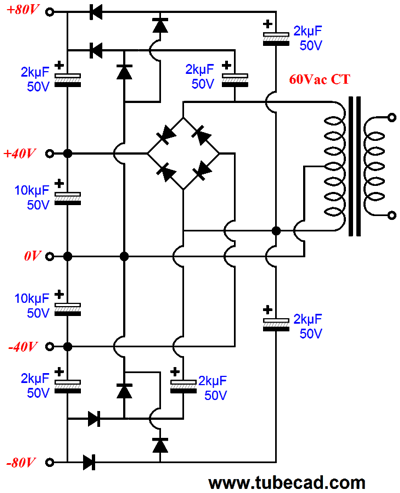
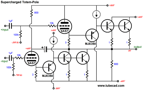
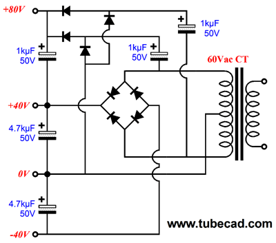
Where did the diodes go and where did the PNP transistors come from? Transistors, unlike triodes and MOSFETs, present a drag at their input, their base, which must be driven as a fairly low-impedance load in itself. In other words, with the diodes in place and with the bases attaching directly to the cathodes, the output triodes would have to drive both the external load and the transistor bases. In contrast, in this circuit variation, the PNP transistor provides both the needed voltage drop and a means for driving the output transistor base. The lower the output transistor’s beta (current gain), the lower in value must be the PNP transistor’s emitter resistor. The power supply for this output stage requires four rail voltages, +80V, +40V, -40V, and -80V—all of which can be derived from a 60Vac center-tapped secondary.
Note how the +/-40V rails get much bigger capacitors, which makes sense as the output transistors will draw much more current than the triodes. Speaking of triodes, the biggest peak current swing we can expect to get out of a single 6AS7 triode with a B+ voltage of 80Vdc is about 200mA. We could get more current, but only by increasing the B+ voltage or going into positive grid voltages. Now, let’s assume that we want to deliver 4A peaks into 8 ohms, which implies 32Vpk and 64W (RMS). Since the transistors are set up to deliver three times the current that the triode does, the total peak current swing per pair of triode and output transistor is 800mA. Thus, a total of eight 6AS7 triodes (four 6AS7 tube envelopes) and eight output transistors will be required per channel. If we wish to drive 4-ohm loudspeakers, then twice that number will be needed. Of course, if we used more transistors with each triode or altered the current ratio between triode and transistor, a single 6AS7 (two triodes) per channel would suffice. But then the triodes would be contributing less current to the output, which diminishes some of the sparkle or novelty that this hybrid-parallel output stage offers. (Think about it: 99% of hybrid power amplifiers use a tube front-end to drive a MOSFET-based output stage, whereas this output stage uses both tubes and transistors to drive the speaker.) Adding more output transistors is easy enough, although I would prefer to use one transistor per output triode.
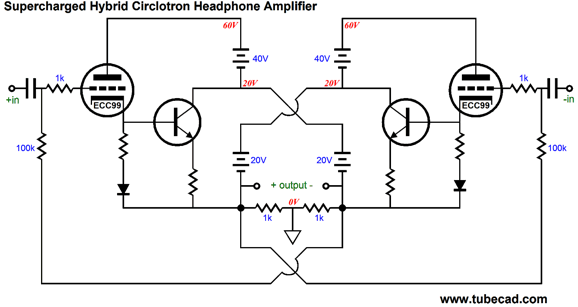
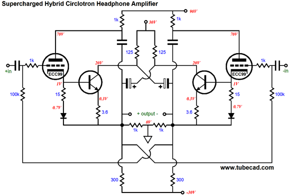
Supercharged Circlotron There so much going on here that I do not know where to begin. (I am also suffering from a head-cold right now, which also adds its weight to the task. In addition, it's Presidents Day and the kids are home from school. Normally, I write these posts while listening to spoken-word podcasts on history, economics, or philosophy! Admittedly, this revelation might explain a great deal to my critics.) The PNP transistors provide the required base-to-emitter voltage drop and drive the output transistor bases. The 4.7k emitter resistor may be too small in value, depending on the output transistors used; it can be replaced by a constant-current source. At startup, we have less to worry about, as the outputs should sit at ground level. In addition, the Circlotron output stage makes fewer demands on the driver stage, as both output tubes get the same amplitude input signal. In contrast, the totem-pole arrangement requires that the driver-stage/phase-splitter take in account the output voltage swings, so the top triode gets a much larger input signal than the bottom triode. The needed power supply is similar to the schematic shown above; remember that two per channel are required.
The biasing of the 6AS7 output tubes gets a nice twist by the cross-coupling of the -40V power-supply rails. This creates a Garter-Belt setup, wherein both output tubes strive to equal each other’s idle current, as an imbalance creates a DC offset that will tend to self-correct itself. Imagine that the positive output drifts slightly positive, while, by necessity, the negative output drifts into negative voltage. The left output's positive drift will increase the right output tube's conduction, while the negative drift on the right output will decrease the left output tube's conduction at idle. With AC music signals, the output stage will ignore the output voltage swings, as they will average to zero at the coupling capacitors connection to the grids. If cathode-bias is used instead of fixed bias, the same cross-coupling can be used. To be honest, the best approach would be to use a DC servo-loop to null the DC offset at idle, but this cross-coupling approach is more elegant.
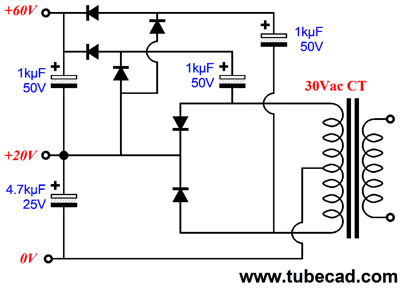
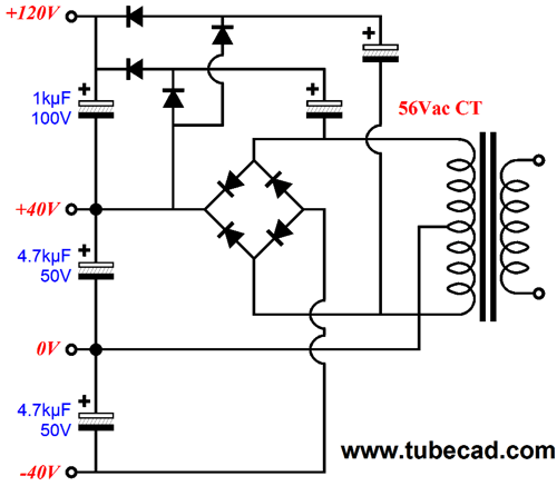
Since no negative power-supply rail is needed, the power-supply design is a tad simpler.
A center tapped secondary is still used, as it allows us to easily create the higher-voltage rail for the output tube. Once again, I must mention that each channel must get two of the above power-supply circuits. That's a lot of power-supply capacitors and rectifiers. If we ware willing to restrict ourselves to strict class-A operation, not the fake stuff of glossy ads and fevered minds, then we can use a single power supply for both channels, as the schematic below makes clear.
This is definitely not your father's Circlotron. First of all, the input coupling capacitors may not be needed, depending on the input stage. Second, the idle current is set to a hot 200mA per channel, so that 10Vpk voltage swings would be possible into 50-ohm loads. If less power is required, the the idle current can be reduced to something more like 60mA per channel. But do not forget that this trick only works within the class-A window of operation. (Brief expansions beyond class-A are okay, but not sustained operation.) Now, a 50-ohm load will require a 160µF coupling capacitor to establish a -3dB frequency of 20Hz, as C = 159155/R/F in µF, so the two electrolytic capacitors should be at least that value. But what about the film capacitors that attach to the triode plates? What should their value be? Since the supercharging transistors make the load appear about five times bigger to the tubes, these capacitors can be about five times smaller in value (but no doubt, much bigger in physical size). In fact, the Zo at the plate, which is equal the triode's rp in parallel with the 1k resistor, must be added to the five-times bigger load impedance, so these capacitors can be as small as 10µF in value. The output transistors still get their low-voltage power supply and the tubes get their high-voltage B+. The large-valued capacitors take the place of the floating power supplies. The power supply for both channels can be derived from a single center-tapped secondary, such as the following design, except that 44Vac CT transformer and smaller power-supply capacitors are used.
Next Time
//JRB |
I know that some readers wish to avoid Patreon, so here is a PayPal button instead. Thanks.
John Broskie
Kit User Guide PDFs
And
High-quality, double-sided, extra thick, 2-oz traces, plated-through holes, dual sets of resistor pads and pads for two coupling capacitors. Stereo and mono, octal and 9-pin printed circuit boards available.
Designed by John Broskie & Made in USA Aikido PCBs for as little as $24 http://glass-ware.stores.yahoo.net/
The Tube CAD Journal's first companion program, TCJ Filter Design lets you design a filter or crossover (passive, OpAmp or tube) without having to check out thick textbooks from the library and without having to breakout the scientific calculator. This program's goal is to provide a quick and easy display not only of the frequency response, but also of the resistor and capacitor values for a passive and active filters and crossovers. TCJ Filter Design is easy to use, but not lightweight, holding over 60 different filter topologies and up to four filter alignments: While the program's main concern is active filters, solid-state and tube, it also does passive filters. In fact, it can be used to calculate passive crossovers for use with speakers by entering 8 ohms as the terminating resistance. Click on the image below to see the full screen capture.
Tube crossovers are a major part of this program; both buffered and un-buffered tube based filters along with mono-polar and bipolar power supply topologies are covered. Available on a CD-ROM and a downloadable version (4 Megabytes). |
|||


| www.tubecad.com Copyright © 1999-2013 GlassWare All Rights Reserved |