| John Broskie's Guide to Tube Circuit Analysis & Design |
| 24 March 2013
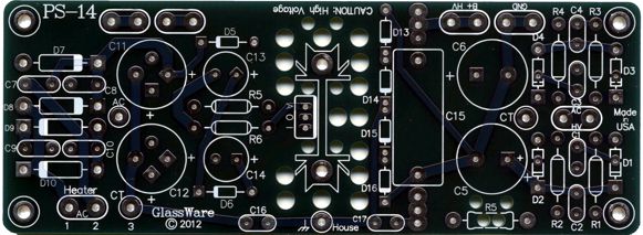
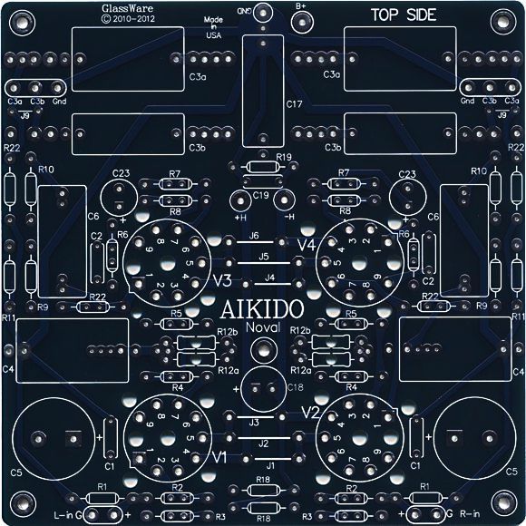
Aikido Noval Stereo PCBs On the other hand, the PS-14 is the same width as the new Aikido noval, so it can be placed right up against the new board. From a few feet, with some squinting, the pair of PCBs would look identical to the old All-in-One board.
(The two PCBs are actually the same color, but scanned at different times.) The PS-1 fully regulated power-supply and Janus shunt regulator are also 6 inches (152mm) wide. This latest Aikido PCB does incorporate a few small improvements, such as the two output coupling capacitors (which I deem essential) and the ability to be configured as an Aikido Push-Pull circuit.
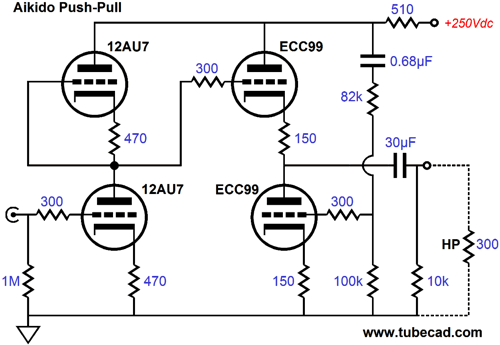
Aikido Push-Pull HPA/LSA
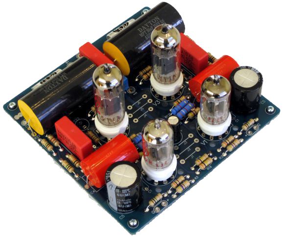
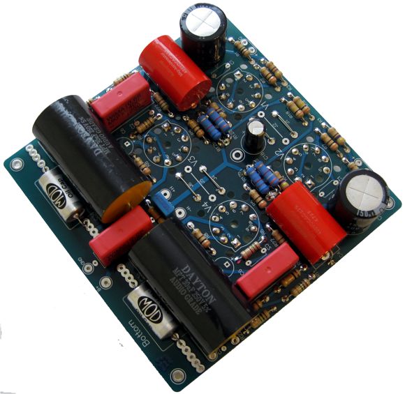
The B+ voltage is a hot 250Vdc and the idle current through the ECC99 is a heavy 23mA. The ECC99's cathode resistors purposely do not get bypass capacitors, which will increase the output impedance, but will also greatly improve the linearity of the output stage. Here is what the bottom of the assembled PCB looks like.
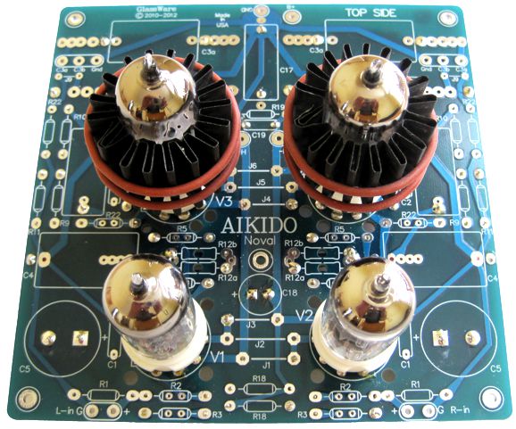
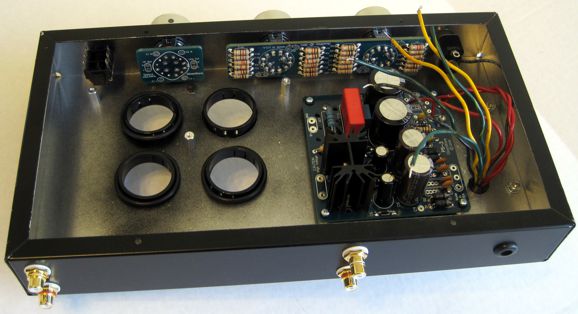
No doubt, some are wondering how this can be the PCB bottom, as it is covered in parts. The answer is that I plan on having the tubes protrude from the chassis top like so many missiles leaving their silos. Now, here is the top of the PCB.
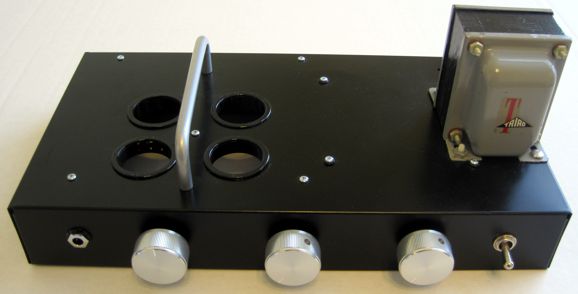
Note the Pearl Audio Tube Coolers; they are essential in this application, as I am running the ECC99 tubes so hard. (Besides, they look cool and seem to provide some needed damping to the tubes.) The input tubes are JJ 12AU7 tubes, the ECC802 long-plate version, which I like a great deal. Below, is the chassis, which amazingly enough looks better in the photo than reality. The chassis is just a Bud box that I had sitting about that I painted black. I had used the box to transport some heavy transformers. A bad idea, as iron beats aluminum in a battle. In other words, the Bud box got banged up a bit. Actually, this was a blessing, as it allowed me to give up on the notion of building a perfect tube-headphone-amplifier chassis. Remember, the perfect is the enemy of the actually built. (I find that I much prefer cheap paper drawing pads or the back of envelopes to draw my many schematics on. Why? Because I am no longer nervous about sullying a perfect piece of paper. I have read that a famous writer always wrote "Damn it" at the top of each typewriter page, before beginning to write in earnest, so the perfectly blank paper would not impede his efforts.) In other words, I knew the chassis could never be perfect, so I didn't get bogged down trying to achieve perfection: this is amazingly liberating.
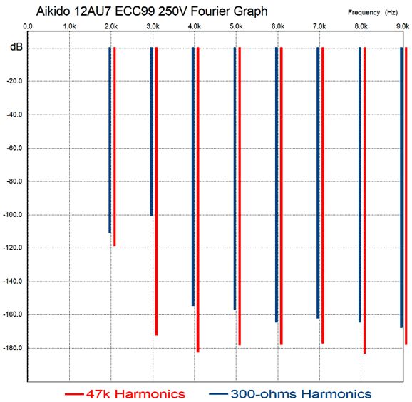
If you look carefully—or is it rudely—you will see that the top of the chassis isn't perfectly flat. And the photo shot at this angle hides some of the orange peel; it's difficult to paint in winter, alas. The toggle switch at the right turns on the power. The two rotary switches next to it control the volume and use the A-5 stereo stepped attenuator. The rotary switch at the extreme left channels the audio signal to either the headphones (Sennheiser HD-650s) or to the rear RCA output jacks. This brings up an interesting question: How does the Aikido push-pull circuit sound when it is driving a 47k load impedance instead of the 300 ohms that it was optimized to drive? The answer is very well indeed. The following is a SPICE simulation graph, showing the distortion harmonics on a 1kHz sine wave at 1Vpk with two load impedances.
The 300-ohm load produces a very clean harmonic structure (blue) that betrays the push-pull signature of more 3rd and 2nd harmonic. The 47k load produces much less distortion, with the typical single-ended signature of more 2nd than 3rd harmonic. Note how with either load impedance, the higher harmonics are effectively nonexistent, as -100dB equals 0.001% distortion. Of course, reality isn't likely to match SPICE, as in the world of SPICE all resistors and tubes are perfectly matched. Nonetheless, this simulation does give us a very good prediction of the shape to which reality will conform. The punch line is that just because this Aikido PP headphone amplifier was optimized to to work into a 300-ohm load doesn't mean that it won't make an exemplary line stage amplifier (and make your friend's fancy $5,000 line stage amplifier sound cheap in comparison ;). The bottom of the chassis, like so many other bottoms, isn't as good looking.
No doubt some are thinking: Good God, John, how many headphone amplifiers do you have already? The answer is not enough. I love my octal LSA/HPA headphone amplifier, but it uses six super expensive NOS tubes. Tubes age. They must eventually be replaced. And I can listen to headphones for up to five hours a day. So, I need a headphone amplifier that is cheap to re-tube. In addition, one day I will jump up out of my chair and pull the headphone amplifier to its death on the floor, so I would prefer to loose the cheaper tubes. Besides, the headphone amplifiers all sound different, even the solid-state headphone amplifiers, even the same solid-state headphone amplifier with different OpAmps. Here is an interesting aside, recently I was testing a handful of different OpAmps in a SE solid-state headphone amplifier I designed. All sounded different, although all held almost identical distortion specs. My favorite was definitely the OPA637, which sounded closest to tubes, but it broke into oscillation easily (in spite of my superhuman efforts), so I settled on the OPA627. Well, a bit later I had gotten more OpAmps to test against the old chips. Oddly enough, they still all sounded different, but this time the difference was far smaller than the time before, not the day and night difference that I had experienced before. I didn't get it, as everything was the same: the same four sets of headphones, the same music source and music selection. But I was wrong; there was one difference: the interconnects. The ones that I had used in the first shootout were handmade polarized cables that Bob Prangnell in New Zealand had sent me and a different interconnect was used this time. Interesting. Thus, I fully expect this new tube headphone amplifier to sound quite different from its older brother and all my other headphone amplifiers. And not one of them is perfect because there cannot be a perfect headphone amplifier or phono preamp or line stage or power amplifier—because there is no perfect signal source. Each record, CD, tape, FM station... will have its preferred mate. This is why I own five or six headphones and five or six headphone amplifiers. Once again, maybe in Plato's heaven there are perfect signal sources and perfect amplifiers and perfect headphones and loudspeakers, but here on Earth, where I happen to live, one size will never fit all. If I had the money and the space, I would love to outfit four rooms with radically different stereo systems. One room would be optimized to playback big Mahler symphonies; another for Mozart symphonies; another for 1960s rock; and another for jazz and chamber music.
Here is a small example: I like Laurie Anderson, the singer and performance artists, finding her engaging and fun. And I own about three of her albums, which I listen to about every five years, more out of a sense of obligation than love. Well, a few weeks ago, I was listening to her Strange Angels album with my octal tube headphone amplifier and HD-650 headphones (with Cardas headphone cords) and dang if I wasn't pleased. She sounded lovely, but more importantly, she came alive, seemingly whispering into my ears. I heard what I had never heard before, but I thought that I should hear. Wow, I finally get it, I thought to myself. And the difference between getting it and not getting it is infinity. I dug out a fine solid-state headphone amplifier (someone else's design) and gave her album a listen. Good, very good in fact, but not magical. I prefer magical. For me, such a moment vindicates all the time and effort I have spent working with audio, tube audio in particular. By the way, in my web search for the her album cover photo, I saw this competing image, which reminds of the sound from the solid-state headphone amplifier, smaller, shaper, but in a glare-filled fashion:
And this one which reminds of an old tube headphone SE amplifier that I built with output transformers, which female friends just loved, but I found too dark and too warm sounding.
Just as each photo of Laurie seems to represent a different personality, each headphone amplifier presents a different sonic portrait. Few can afford to own five or six power amplifier and four or five sets of speakers, whereas headphones and thier amplifier are neither that large or expensive. I almost forgot to say that the Aikido noval stereo boards and part kits are available now at the GlassWare/yahoo store. I was missing one critical part, the RC filter capacitors, which according to the online tracking, will arrive this coming Tuesday, so I can finally release them. (I planned on mentioning how difficult it has been recently for me to track down all the parts I need for the kits, but it is just too depressing.)
Next Time
//JRB |
I know that some readers wish to avoid Patreon, so here is a PayPal button instead. Thanks.
John Broskie
Kit User Guide PDFs
E-mail from GlassWare Customers
High-quality, double-sided, extra thick, 2-oz traces, plated-through holes, dual sets of resistor pads and pads for two coupling capacitors. Stereo and mono, octal and 9-pin printed circuit boards available.  Aikido PCBs for as little as $24 http://glass-ware.stores.yahoo.net/
Support the Tube CAD Journal & get an extremely powerful push-pull tube-amplifier simulator for TCJ Push-Pull Calculator
TCJ PPC Version 2 Improvements Rebuilt simulation engine *User definable
Download or CD ROM For more information, please visit our Web site : To purchase, please visit our Yahoo Store: |
|||
 In my over zealous haste to quickly build this project, I made three of the tube holes a tad too big. (I hand drilled rather than punched or drill pressed.) The power supply is a


| www.tubecad.com Copyright © 1999-2013 GlassWare All Rights Reserved |