| John Broskie's Guide to Tube Circuit Analysis & Design |
04 January 2014
For those of you who still have old computers running Windows XP (32-bit) or any other Windows 32-bit OS, I have setup the download availability of my old old standards: Tube CAD, SE Amp CAD, and Audio Gadgets. The downloads are at the GlassWare-Yahoo store and the price is only $9.95 for each program. http://glass-ware.stores.yahoo.net/adsoffromgla.html So many have asked that I had to do it. WARNING: THESE THREE PROGRAMS WILL NOT RUN UNDER VISTA 64-Bit or WINDOWS 7 & 8 or any other 64-bit OS. I do plan on remaking all of these programs into 64-bit versions, but it will be a huge ordeal, as programming requires vast chunks of noise-free time, something very rare with children running about. Ideally, I would love to come out with versions that run on iPads and Android-OS tablets.
New Products (Don't you hate that we must state so obvious a fact—as if anyone actually thought that a $50 NOS Sylvania 6SN7 would come with a $9.95 part. At what point are we allowed not proclaim the legalistic disclaimer. For example, if an ad for a new Honda car shows the car parked in front of a ten-million-dollar mansion, can Honda get away without stating that the mansion is not included in the $27,000 base price of the car? And what about the fine-looking woman sitting in the passenger seat and the handsome dog in the back seat...)
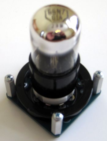
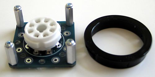
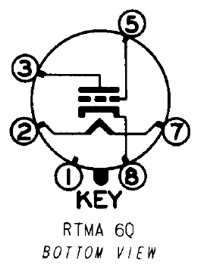
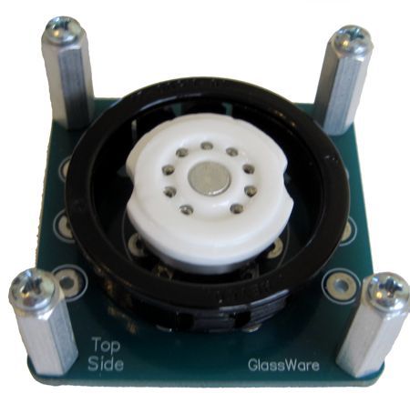
The PCB is universal because you can use any octal tube you want and wire it up as you please. For example, I own a bunch of NOS 6J5 and 12J5 tubes, which hold a single 6SN7 triode.
I would love to build an Aikido using eight of them, with separate regulated heater power supplies, each regulator referenced to different DC voltages, say +40Vdc and +290Vdc. Why? Imagine that a hot B+ voltage of 500Vdc, which means that the top triodes would absorb the top 250 volts and the bottom half the bottom 250V. Normally, such a setup would be a no-no, as the cathode-to-heater voltage limit would be exceeded (usually 100V), as the the top cathodes would be 250V away from the bottom cathodes. With eight Universal Octal socket kits, I could assemble such an Aikido line stage amplifier. Mind you, it would take some work, as the two floating heater power supplies are the least of it; the 500V regulator would take some effort to produce and the chassis would have to be fairly large to hold the eight octal tubes. Nonetheless, such a beast could easily prove the finest linestage in existence. Period. I haven't mentioned it it so far, but the intended use for the Universal Octal kit is for those designs that have the tubes protruding through the chassis top panel, much like MX missiles leaving their silos. But, if you choose, you can mount the socket's PCB to the bottom panel instead; it is just not as snazzy looking.
Of course, I could not forget the noval-tube fanciers, so there is also a Universal Noval PCB & socket kit, which includes a black plastic 1.5in hole trim and four sets of aluminum, hex standoffs and screws and rubber O-rings, but—alas—no NOS Amperex cinch-waist, $200 6DJ8 tube ;)
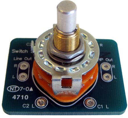
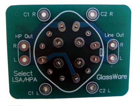
The next offering is the new Select LSA/HPA rotary switch and PCB, which allows you not only to select where the output signal goes, but which capacitors are used for each task.
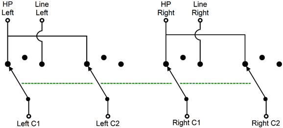
Headphones, even high-impedance ones, such as the 300-ohm HD650 & HD800 from Sennheiser, require fairly large coupling capacitors, say 30µF; but line outputs usually use coupling capacitors that range from 0.1µF to 4µF. In addition, the big coupling capacitors that attach to headphones, are usually only very good, whereas the smaller coupling capacitors that attach to our power amplifiers are usually quite excellent indeed. Well, with the Select LSA/HPA switch, we can use both types of coupling capacitors. The rotary switch is a 3-pos, 4-pol design, which effectively allows us to give each of the four coupling capacitors its own three-position switch, as the schematic below shows.
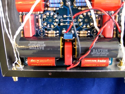
For example, in a LSA/HPA project that I just finished, I used both 30µF Dayton and Jantzen Audio Superior Z-Cap coupling capacitors. The line out got just the 1µF Jantzen Audio capacitor, while the headphones got both in parallel, with C1 being the 1µF capacitor; C2, the 30µF capacitor. The rotary switch present three positions, so the center position is mute, for both headphones and line outs.
(I have to install 1M resistors at each output RCA jack, as they will connect the hot pins to ground, which will prevent hum or popping sounds, when the switch hits the mute position.) Since the last fifteen years of experience have taught me that when I mention such a project, much e-mail will follow, which will all ask the same questions, such as: Which tubes did I used? What was B+ voltage? Which attenuator? What about the power transformer? And so on...
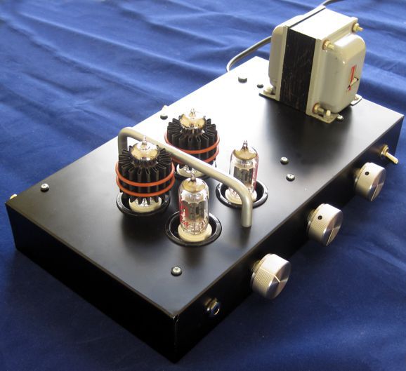
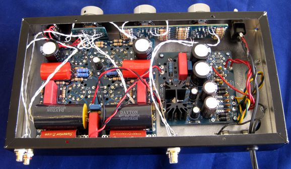
Aikido PP LSA/HPA Project The result was a super-tight fit that required careful insertion of each piece. After a few headaches, I let the project sit idle for months. But with chilly weather, I had more reason to stay inside and finish several unfinished projects.
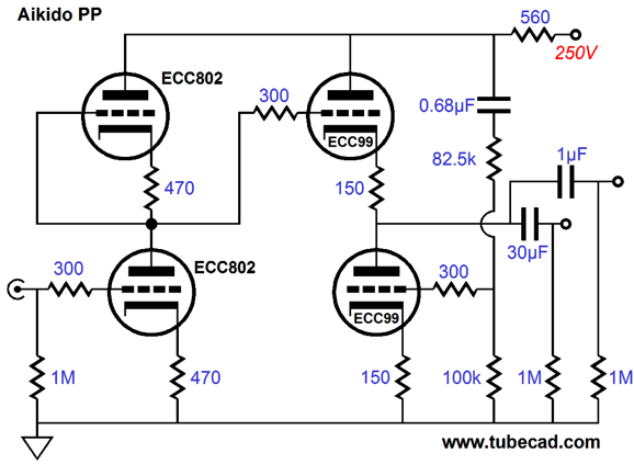
Well, after much swearing, I got it together. I couldn't use the high-quality 1µF coupling caps that I wanted to use, as they were too fat, so I used the thinner Jantzen Audio capacitors instead, which actually turned out well, as they sound better than I remember them sounding in line-stage use and they certainly help the Dayton Audio 30µF capacitors sound much more refined and detailed, without sounding in the least harsh, which is essential in a headphone amplifier. I measured my wall voltage and found that it runs hot: 123Vac, instead of the typical 117Vac. This might help explain why the old Triad tube power transformer (model R8-A) works so well. It holds three secondaries: 5Vac@2A, 6.3Vac@2.5A, and 250V-0V-250V CT @ 75mA. I placed the 5Vac and the 6.3Vac windings in series, so I could get 12Vdc out of the PS-3's heater regulator. It works. This project just uses a two-lead zip cord to attach to the wall socket. I planned on replacing the power cord later, when I can find the fancy shielded three-wire power cable I own. But then, I might not. Unfortunately, my house ground and the wall neutral see about 500mV of AC between them (should be 0Vac), which explains why I sometimes get hum when I connect the house ground to the chassis in some equipment. The circuit is an Aikido push-pull that uses JJ ECC802 (12AU7) tubes for the first stage and JJ ECC99 tubes for the output tubes. I have changed the series resistor at the top, since the last time I posted the schematic. The ECC99 output tube idle at about 17mA and they do require the Pearl Audio Tube Coolers for actual cooling, not just tube envelope damping.
If the Bud box were just one inch deeper, I would have no reservations recomending this project to other audiophiles. The box was only 13in wide by 7in deep by 2in tall. A better choice would be 10 inches deep and 2.5 or 3 inches tall. Well, how does it sound? After the fight I put up to get the this project done, I was predisposed to not like the sonic results. My ears, however, wouldn't put up with that sort of nonsense and I fell in love with LSA/HPA almost instantly. My HD650s gladly receive the output from the headphone jack, which prompts a wonderfully natural presentation. I even tried my Grado SR-225 headphones and the results were surprisingly good; true, the bass was a tad thin, but the mids and highs were fine. Considering that the Grado headphones are almost one tenth the impedance of the HD650 headphones, this is a miracle. I ran some SPICE simulations of the circuit with a 32-ohm load. The results were also much better than I expected. The line outs also sound much better than I expected. In fact, I first listened to the line outs and I was immediately pleased by how quiet the LSA/HPA was. As the first notes of music poured forth, I was impressed. I wonder if the the very high idle current through the ECC99 isn't working some magic, as I do not remember them (or the coupling capacitors) sounding this good. Well, running triodes hard under high current and with high plate voltage will move the triode's operating point into the most linear portion of the the triode's plate curves, but at the expense of a shorter life span. (An excellent trade, if you ask me. I know so many audiophiles who do not bat an eye at spending $2,500 for interconnects, but who grumble and gripe about having to replace batteries and tubes.)
Next Time
//JRB
|
I know that some readers wish to avoid Patreon, so here is a PayPal button instead. Thanks. John Broskie
Kit User Guide PDFs
And
High-quality, double-sided, extra thick, 2-oz traces, plated-through holes, dual sets of resistor pads and pads for two coupling capacitors. Stereo and mono, octal and 9-pin printed circuit boards available.
Designed by John Broskie & Made in USA Aikido PCBs for as little as $24 http://glass-ware.stores.yahoo.net/
The Tube CAD Journal's first companion program, TCJ Filter Design lets you design a filter or crossover (passive, OpAmp or tube) without having to check out thick textbooks from the library and without having to breakout the scientific calculator. This program's goal is to provide a quick and easy display not only of the frequency response, but also of the resistor and capacitor values for a passive and active filters and crossovers. TCJ Filter Design is easy to use, but not lightweight, holding over 60 different filter topologies and up to four filter alignments: While the program's main concern is active filters, solid-state and tube, it also does passive filters. In fact, it can be used to calculate passive crossovers for use with speakers by entering 8 ohms as the terminating resistance. Click on the image below to see the full screen capture. Tube crossovers are a major part of this program; both buffered and un-buffered tube based filters along with mono-polar and bipolar power supply topologies are covered. Available on a CD-ROM and a downloadable version (4 Megabytes). |
||
| www.tubecad.com Copyright © 1999-2014 GlassWare All Rights Reserved |

