| John Broskie's Guide to Tube Circuit Analysis & Design |
07 February 2014
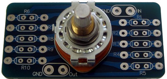
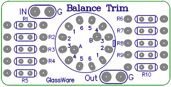
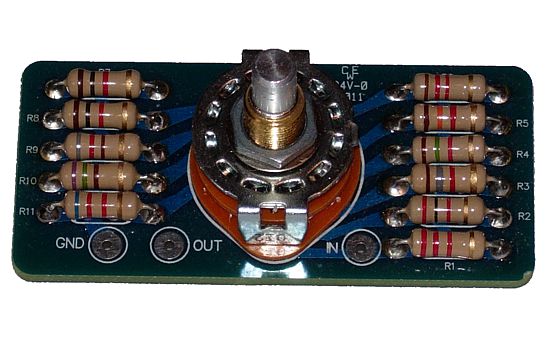
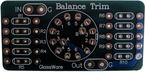
In my last post, I revealed the arrival of the Balance Trim PCB and rotary switch.
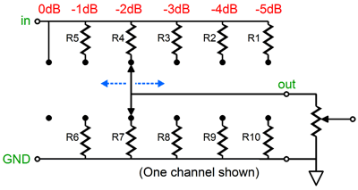
The Balance Trim is a simple ladder attenuator, with six positions, which can be used with a volume potentiometer (or fancy stepped attenuator). The switch is a 2-pol, 6-pos, shorting design that never places more than two resistors in the signal path.
The volume control's resistance must be factored into the ladder attenuator's resistor calculations. The following tables show -1dB decrements for both metal-film and carbon-film resistors.
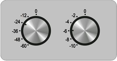
Each channel gets its own Balance Trim control, which will undoubtedly bother some old-timers, who fondly remember the single balance control knob of their youth. But as Jeanne Moreau so aptly put it, "Nostalgia is when you want things to stay the same. I know so many people staying in the same place." Not that for a second am I endorsing the idea that all change is good, as it certainly isn't. No, what I want is small, reversible, incremental changes for the better. For some insane reason, many believe that they must turn both Balance Trim controls at once. Not so. The whole point is to establish balance. If the right speaker is playing louder than the left speaker, just turn down the right speaker. By the way, the Balance Trim can be used a volume control, particularly when cascaded into another Balance Trim. Why? Two Balance Trims in cascade equal 36 steps of attenuation, which is 12 more decrements of attenuation than the usual 24-position stepped attenuator from GoldPoint or DACT; more importantly, the two Balance Trims in cascade never present more than four resistors in the signal path due to their being ladder types, not series attenuators. This two-knob, 36-position, ladder stepped attenuator would require only 20 resistors per channel, not the 36 resistors that a series attenuator would need.
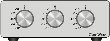
By the way, three Balance Trims in cascade would yield 6 * 6 * 6 steps of attenuation, or 216 steps. Why would anyone need so many? Perhaps you are doing test measurements and you require a precise amount of attenuation, for example -90dB. Well, the following stepped-attenuator box would be one easy and shockingly inexpensive solution. (If you have ever priced lab-grade attenuators, you will know how expensive such a stepped-attenuator box costs.)
Alternatively, you might wish to make precise adjustments to the balance, which such a stepped attenuator would allow. In this example, from 0db down to -97.5dB. But what if you own a piece of old audio gear that already holds a balance control, albeit a not very good one, as it uses a dual potentiometer that doesn't center or makes scratchy noises? Well, you could use just one Balance Trim as a dual-channel balance control. How? Just use one Balance Trim on the left channel, parking the knob on the -2dB position; then, use two resistors on the right channel to drop its signal by -2dB. Thus, with the Balance Trim set at -2dB, both channels get the same signal level. But as the single Balance Trim knob is rotated, the left channel will get either more or less signal, at 1dB increments or decrements, allowing a small and subtle changes in balance. Of course, a seven-position rotary switch would be better, as it would allow equal number of decrements and increments, but such beasts are not made, alas. Or, depending on the circuits used, you could use a Trim-1 series attenuator as a balance control replacement.
The Trim-1 offers 11 positions, which is perfect, as an odd number was required to center the switch. All that is required is to replace R11 with a jumper wire and use the same value resistors throughout. (You could get fancy and put in place some fancy attenuation curve, but I would stick to 10 equal-valued resistors. Sometimes it's better not to be too clever. Just do not quote me back to me in the future.)
Of course, the amount of possible balance adjustment is up to you. The best thing about DIY audio is the freedom—but, then, it is also the worst thing about it. Hell, I can imagine two balance controls per channel, one coarse and one fine, much as a good microscope offers two focus control knobs. I once modified a tube-based guitar amplifier that held a single hum-null potentiometer by adding a second fine null potentiometer. The procedure was simple enough, center both knobs, then adjust the coarse hum-null knob until the deepest null was attained, then adjust the fine control for an even deeper null in hum. Nostalgia dictates one knob, intelligence says otherwise.
The Balance Trim is available now at the Yahoo-GlassWare store and is sold with or without the resistors.
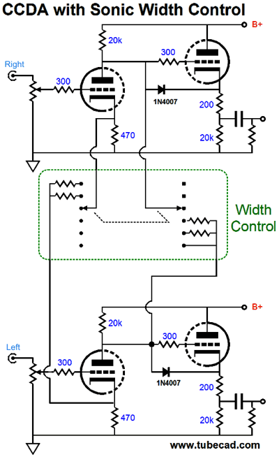
More Sonic Control
When parked at the third position, the control leaves the signal unchanged. Turn the knob all the way clockwise and CCDA puts out a mono signal. Turn in the opposite direction and the CCDA puts out wider sound-stage, with less center-fill.
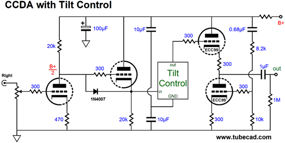
Adding a Tilt Control to the CCDA
The CCDA's first stage, a grounded-cathode amplifier, splits the B+ voltage and the B+ noise at its output. The CCDA's second stage, a cathode follower, then relays this halved B+ noise to the Tilt Control, which in turn passes it on to the ACF, which then applies a countering current flow through the output to null the B+ noise at its output. Magic. Well, it's like magic, if you cannot figure out how it works. The following schematic shows how it works.
The two 10µF capacitors in series define a 50% AC voltage divider, which attaches to the Tilt Control's ground pad. Note how the above B+ noise null only occurs if both the CCDA and ACF stages share the same B+ connection. In other words, adding an RC filter to CCDA's B+ connection will undo the magic. Of course, there is no reason why the sonic-width control could not be added to this circuit.
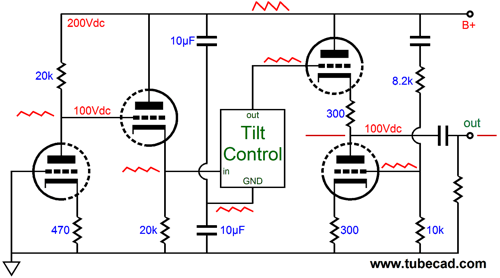
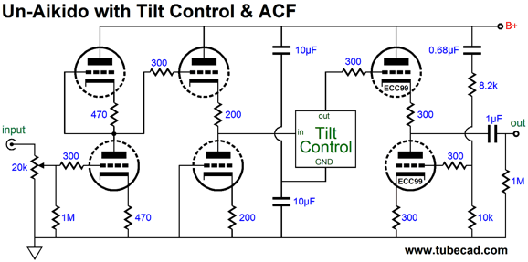
Adding a Tilt Control to the Aikido I often get requests for an Aikido with balanced outputs capable of driving 600-ohm loads. My recommendation is the following circuit.
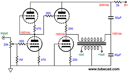
The un-Aikido gain stage now spills 50% of the power-supply noise at its output; but then, so, too, does the two 30µF power-supply capacitors, so the output transformer's primary never sees a power-supply-noise delta, so no power-supply noise couples to the secondary. No delta, no signal. Now, if the two big capacitors didn't also help the rest of the circuit out by working as power-supply-filter capacitors, I would be less inclined to recommend this topology. But since we do need power-supply capacitors, this approach makes a lot of sense. Think about this: even if the two 30µF capacitors are flaky in some way, perhaps due to excessive inductance or ESR, the un-Aikido stage will halve this flakiness and the output transformer will ignore it, dropping it from its output. Remember, no delta, no signal. So, we can add a Tilt Control to an existing Aikido stage thus:
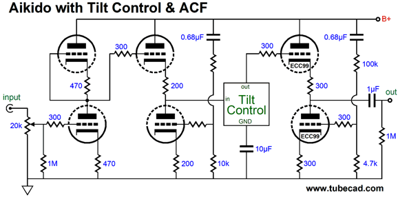
Note the two 10µF capacitors, which are needed to "ground" the Tilt Control and the elimination of the Aikido's voltage-divider resistors. Of course, we could use a normal Aikido to drive the Tilt Control.
In this example, the Aikido presents a clean output to the Tilt Control, which then relays the signal to the ACF, which then undoes the power-supply-noise leakage that a simple cathode follower would spill out. Yes, simple cathode followers are not blameless in terms of PSRR. Note the single 10µF capacitor that attaches to the Tilt Control's ground pad, effectively "grounding" the control. (A much smaller capacitor could be used, say 1µF, but the larger value hammers home the point that the Tilt Control is being grounded through this capacitor.) Note how the Aikido, the Tilt Control, and the ACF are all DC coupled. Just like the previous CCDA circuit, there is no reason why a sonic-width control could not be added to this circuit.
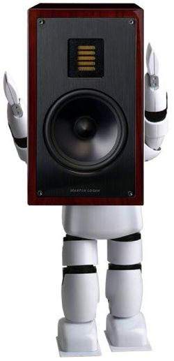
Robo Speaker Stands Each fellow held his speaker, as I orchestrated their position, much as an airport plane-marshaller directs the pilot's path. "Up, tilt back, a bit further apart, no, closer, move away from the back wall, that's it, yes, perfect, stop fidgeting..." In less than a few minutes, I had found the perfect placement; well, at least for that LP. What I can never forget is that during one brief moment, the two guys had fallen into perfect harmony, each placing his speaker at the optimal position, resulting in the most amazing sound stage, truly holographic. Then, alas, it was gone. Indeed, I could never replicate the placement, as my stands were not tall enough and didn't allow for tilting the speakers back. Nonetheless, the memory lingers—even after 30 years.
Ripping LPs
Adolph Hitler and Speaker Cables
Next Time
//JRB |
I know that some readers wish to avoid Patreon, so here is a PayPal button instead. Thanks. John Broskie
Kit User Guide PDFs
And
High-quality, double-sided, extra thick, 2-oz traces, plated-through holes, dual sets of resistor pads and pads for two coupling capacitors. Stereo and mono, octal and 9-pin printed circuit boards available.
Designed by John Broskie & Made in USA Aikido PCBs for as little as $24 http://glass-ware.stores.yahoo.net/
The Tube CAD Journal's first companion program, TCJ Filter Design lets you design a filter or crossover (passive, OpAmp or tube) without having to check out thick textbooks from the library and without having to breakout the scientific calculator. This program's goal is to provide a quick and easy display not only of the frequency response, but also of the resistor and capacitor values for a passive and active filters and crossovers. TCJ Filter Design is easy to use, but not lightweight, holding over 60 different filter topologies and up to four filter alignments: While the program's main concern is active filters, solid-state and tube, it also does passive filters. In fact, it can be used to calculate passive crossovers for use with speakers by entering 8 ohms as the terminating resistance. Click on the image below to see the full screen capture.
Tube crossovers are a major part of this program; both buffered and un-buffered tube based filters along with mono-polar and bipolar power supply topologies are covered. Available on a CD-ROM and a downloadable version (4 Megabytes). |
|||||||||||||||||||||||||||||||||||||||||||||||||||||||||||||||||||||||||||||||||||||||||||||||||||||||||||||||||||||||||||||||||||||||


| www.tubecad.com Copyright © 1999-2014 GlassWare All Rights Reserved |