| John Broskie's Guide to Tube Circuit Analysis & Design |
| 07 June 2014
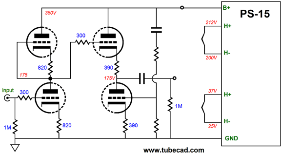
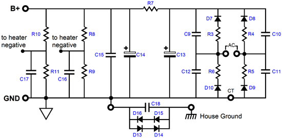
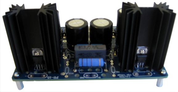
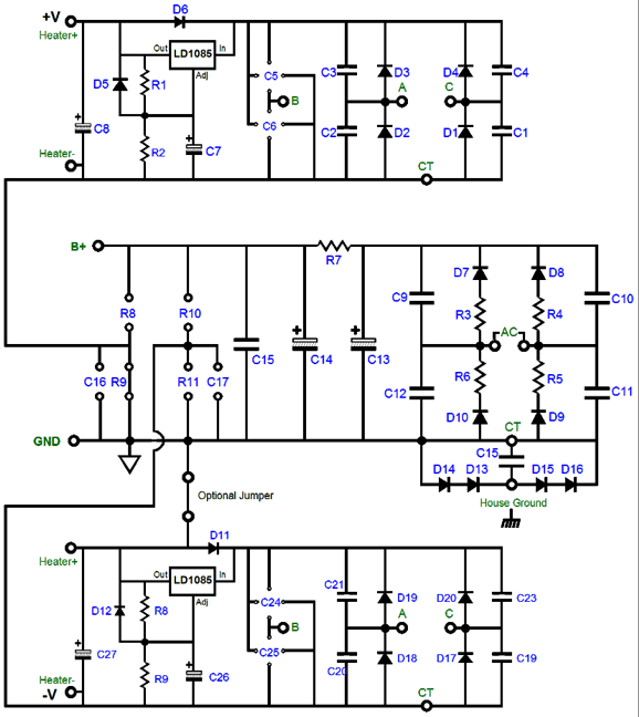
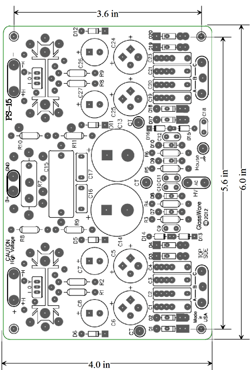
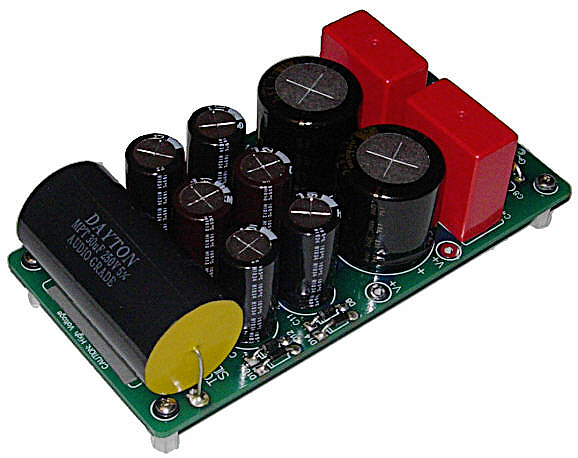
The PS-15 is a new GlassWare power supply kit for tube fanciers. On this six by four inch, extra thick (0.094), 2oz-copper traces, USA-made PCB resides both a high-voltage power supply and two low-voltage regulators—each finding its own raw power supply, including the rectifiers and power-supply reservoir capacitors. In other words, except for the power transformers, the PS-15 PCB holds all that is needed to make a fine high-voltage power supply suitable for complex tube circuits. What another power supply? Yes, indeed, as it fills a gap. The PS-15 was designed for those who need a high-voltage power supply with two sets of regulated low-voltage power supplies (usually for powering heaters but not always). Why would anyone need two low-voltage regulators? More often than you might imagine. I created the PS-15 precisely because it was something that I have needed many times before in building a tube project. For example, say I wanted to make an Aikido line stage that ran a B+ voltage of 350V. The problem was that the top and bottom triodes would halve the 350V to 175Vdc per triode, which means that the triode's maximum cathode-to-heater voltage would be exceeded with a single heater power supply. But if I configured the tube horizontally, rather than vertically, and if I used two heater regulators, everything would be fine. In the following Aikido circuit, top and bottom tubes must be the same type, for example both 6SN7, 6CG7, 12AU7, 12BH7, ECC99, or 5687 tubes, which is a small tradeoff; having the cathode-to-heater voltage for each tube be only 25V, however, is a real plus.
The high-voltage portion of the PS-15 power supply uses a high-speed solid-state full-wave bridge rectifier circuit (or full-wave center-tap rectifier circuit) and a simple RC filter to achieve a fairly quiet high-voltage output, which can span up to 350V at the output, with 400V capacitors; or, up to 200V, with 250V capacitors; the choice is yours.
The two low-voltage regulators can power the tube heaters, whose cathodes might be hundreds of volts apart, as each low-voltage regulator circuit is independent. Or, perhaps, you might give each channel its own heater power supply. Or, power something altogether different, such as an external DAC. In addition, each low-voltage regulator’s power supply is flexible enough to allow either a conventional full-wave-bridge rectifier arrangement or a two rectifier voltage-doubler configuration, allowing for more latitude in power transformer selection; this regulator can be set to either 5V, 6.3V, 9V, 12V, 12.6V, 15V, 18V, 20V or 24V. In addition, the PS-15 can DC reference both heater regulators to differing positive voltages or be left floating, with only a small capacitor to ground. Moreover, the two low-voltage regulators can be configured as a low-voltage, bipolar power supply referenced to ground, for use with OpAmps.
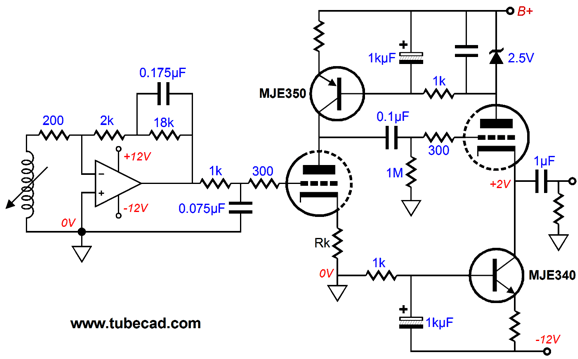
Other circuits I had in mind that needed the PS-15 was several hybrid phono stage designs. For example, here is a hybrid design that uses an ultra-low-noise OpAmp as the first stage, which then passes its output through a passive equalization network to a tube stage at the end.
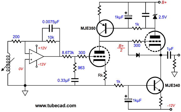
The low-noise OpAmp is configured as an inverting amplifier, while the tube stage also inverts the signal, so the two inversions equals no inversion. The OpAmp's feedback loop imposes the 50H and 500Hz equalization, while the 1k and 0.075µF RC filter imposes the 2122Hz low-pass portion of the RIAA equalization curve. Of course, we could switch things around, placing the 2122Hz low-pass filter before the shelving network.
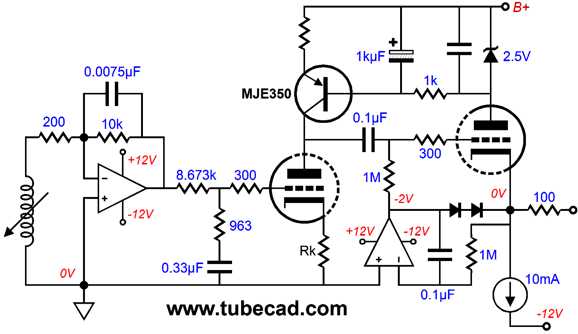
Now that I look at both schematics, I think that the second one would work better. But at the same time, I prefer giving the cathode follower the lion-share of B+ voltage, which the internal coupling capacitor allowed in the first design. Okay, how about we combine both designs and add DC coupling at the output?
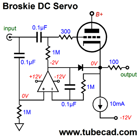
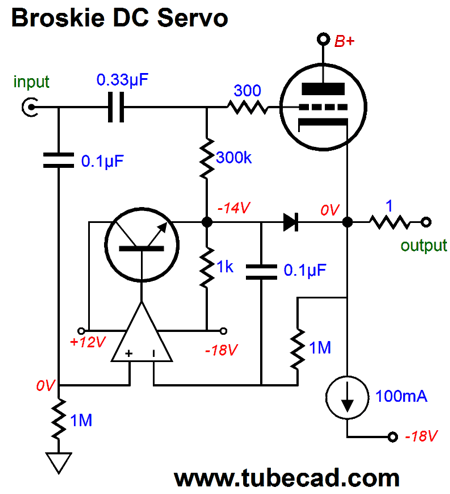
The second OpAmp is used in the DC servo loop, which strives to keep the DC offset at the output low. At start-up, when the tube is cold and has yet to conduct, the two diodes in series save the day, as they allow the OpAmp's output to pull against the 10mA constant-current source and prevent a DC offset. Once the tube is hot and conducting current, these two diodes fall out the circuit, as the cathode will be several volts more positive than the grid, so the diodes will be reverse biased. (This means the maximum negative output voltage swing will be limited to about 3.4Vpk in this example, which is insanely hot for a phono stage, so no worries.) For line-stage or headphone amplifier use, greater output voltage swing might be needed, which this DC servo won't allow. The solution is my variation on the DC servo.
Note how the OpAmp's non-inverting input is no longer grounded directly; instead, in this circuit, it finds its path to ground via a 1M resistor. Also note how the input signal feeds both the triode's grid and the OpAmp's non-inverting input. Why? In this setup, the OpAmp's output follows the input signal, allowing the triode's cathode to swing much bigger voltages. How big? It depends on the load impedance. If the load is anything above 1k, the triodes cathode will always be more positive than the OpAmp's output. Indeed, the bigger limitation to large voltage swings is the constant-current source's idle current against the load impedance. For example, if ±10Vpk is viewed as a reasonable voltage-swing limit with the ±10Vdc voltage rails, then we can divide 10V by 0.01A and get 1kohms as the lowest possible external load impedance. I know that some might worry that the OpAmp will somehow take over and impose its sonic signature. Except for the those cases where someone was foolish enough to use a non-unity-gain-stable OpAmp, such as the OPA637, which would provoke OpAmp oscillating, the OpAmp cannot do much damage, however, as its output signal must travel through the 1M resistor to the triode's grid. Thus, the grid largely ignores the nearly identical signal that feebly leaks through he 1M resistor, as the robust signal coming through the 0.1µF coupling capacitor is a thousand times stronger. If you wish to make it stronger still, you could increase the coupling capacitor's value to 1µF. As shown, this circuit would make a fine No-Gain/No-Pain unity-gain line stage. Use a robust enough of a tube (or several triodes in parallel), and you could drive headphones. Hell, if you used enough robust tubes in parallel, such as the 6AS7, 6C33, or EL509, and if you added an NPN power transistor to the OpAmp's output, you could drive loudspeakers.
Note the dissimilar bipolar rail voltages, which depending on the OpAmp used, could be even greater, say +6.3Vdc and -24Vdc. Why? A larger negative rail voltage will allow bigger output voltage swings; moreover, some tubes will require a greater negative bias voltage. Another setup, wherein the PS-15 would come in handy, would be to use one low-voltage regulator for the tube heaters and the other for powering an external DAC or Squeezebox or IC phono stage—basically any audio component that came with 5V or 9V or 12V switcher wallwart. Replacing the switcher with a linear regulator can make huge improvement in the sound from the device.
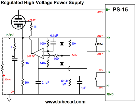
Another possible use for the PS-15 is as the backbone of a regulated high-voltage power supply, as one of the low-voltage regulated outputs could be used to power the 12B4 tube pass device's heater and a control OpAmp, as shown below.
Yes, it's a bit complicated, but not too bad. The 12B4 pass device sees the 330Vdc on its plate and 250Vdc at its cathode and 243.5Vdc at its grid, which allows 30mA to flow through the triode. The OpAmp, which can be a slick, low-noise, low-distortion device, such as the OPA627 (not OPA637), must be unity-gain stable. The way this regulator works is simple enough: the OpAmp strives to keep its two inputs always at the exact same voltage; always. The only way that this is possible is if the voltage drop across the 10k resistor equals the voltage drop across the 100k resistor; in turn, the only way that is possible is if the regulator's output voltage equals 250Vdc. If the output voltage climbs upward, the voltage presented to the OpAmp's non-inverting input becomes negative relative to its inverting input, so the OpAmp's output swing negative until the regulator's output falls back inline wit 250Vdc. Conversely, if the output voltage falls below 250Vdc, the OpAmp's non-inverting input sees a positive voltage relative to its inverting input, so its output swings positively. In other words, not only are we using the floating 12Vdc regulated voltage to power the 12B4's heater and the OpAmp, we are using the this fixed 12V voltage as a voltage reference for the high-voltage regulator. That was the DC operation of this regulated high-voltage power supply. The AC operation is a bit different.
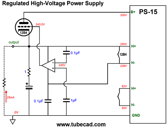
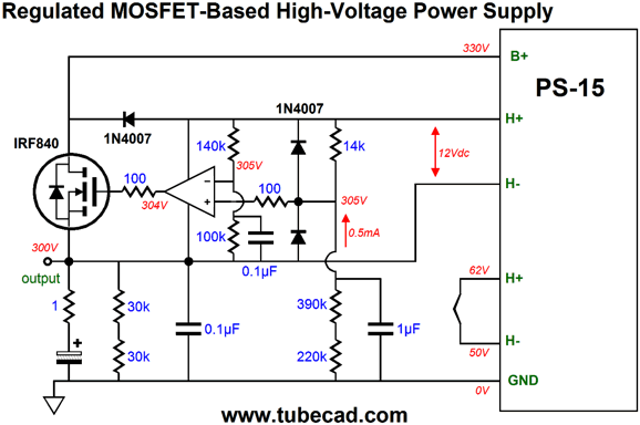
In AC terms, the OpAmp compares the regulator's output with the ground and any difference at the output is brought in line by the OpAmp's considerable open-loop gain. The 12B4 could be replaced by a pentode, such as my favorite, the EL84, or a solid-state device. Using a typical enhancement N-channel MOSFET as the pass device will require a slight rearrangement, as the gate must be driven more positive than the source.
Once again, the regulator strives to maintain identical voltages on the OpAmp's inputs, which is only possible when the regulator's output voltage equals 300Vdc, as that is the only voltage that develops the 7V voltage drop across the 14k resistor. If the 390k and 220k resistors were replaced by a single 510k resistor, the regulator's output voltage would fall to 250Vdc. Not only are series regulators possible, but shunt regulators as well.
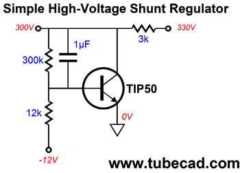
The -12Vdc power-supply rail is used as a voltage reference for this shunt regulator. If the output voltage climbs too high, the NPN transistor conducts more, bringing the output voltage back in line. Conversely, if the output voltage falls too low, the NPN transistor conducts less, allowing the 3k series resistor to pull the voltage up. As shown, this simple shunt regulator is not complete, as safety features, such as a few extra diodes are missing. The following is a more complex shunt regulator.
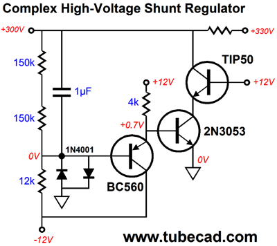
Do you see the diamond? The BC560 is a low-noise PNP transistor and the 2N3053 is a surprisingly fine NPN transistor, while the TIP50 is a high-voltage power transistor that comes in the TO-220 package. The 2N3053 and TIP50 are in cascode. Effectively, the 2N3053 is in charge and its variation in current conduction sets output voltage and scrubs away the noise. As you can guess, I could come up with an easy dozen more hybrid phono or line stages or regulated power supplies. But the big problem I faced was getting a simple and convenient power supply that could power such designs, which is why I created the PS-15. Since the two low-voltage regulator circuits on the PS-15 are independent, we can configure them as a low-voltage bipolar power supply.
Yes, two positive regulators can create a bipolar power supply. In fact, this setup is preferred, as no one makes a great negative regulator; or put differently, no one makes a negative regulator as good as the LM317, let alone as good as the LD1085 or LT1085. One small trade off is that a center-tapped secondary cannot be used to develop the raw power supply voltages for the bipolar regulators. But as most power transformers offer two equal secondaries, say 12Vac and 12Vac, this is not much of a problem.
The PS-15 kit is available now at the GlassWare-Yahoo store.
Non Grata Gratuitous SRPP While on this topic, I should mention that I got one e-mail that stated that the reader didn't quite get what I meant by "non-gratuitous," so I will provide an example of an SRPP being used because it was needed.
The circuit above is a design that actually requires an SRPP input stage, as the SRPP must drive the 12AX7's low-valued cathode resistor and its cathode, as the 12AX7-based stage is a grounded-grid amplifier. (Since this was my creation, I could not help adding the Aikido-esque injection of the power-supply noise into the 12AX7's grid, thereby nulling the noise at the output. By the way, the assumption is that the 12AX7 and the following 12AU7 are held within a 12DW7/7247/ECC832 tube. In addition, I should point out that this circuit puts out a gain of 42 and offers a fairly good PSRR and a low output impedance.) The SRPP topology, however, is usually required to drive an external low-impedance load, not one internal to the circuit.
In the circuit above, we see an SRPP output stage driving a 300-ohm headphone element. The input stage is a grounded-cathode amplifier with an active load, which effectively multiplies the resistance of the two cathode resistors (680 and 4.3k) by (mu + 1). The negative feedback loop (the 6.8k resistor and 2µF capacitor) reduces the gain, distortion, and output impedance. In SPICE simulations, the above headphone amplifier delivered exemplary performance. I can easily imagine many other legitimate uses for the SRPP topology. For example, the SRPP could drive the primary of step-up signal transformer, whose secondary feeds the grids of a push-pull, 300B-based output stage.
What is the load presented to the SRPP circuit shown above? Since the winding ratio is one-to-ten, the impedance ratio is equal to 10², or 100; thus the SRPP sees a load impedance of (10k + 10k)/100, or 200 ohms. Yes, not 20k, but just 200 ohms, which is a tough load for any tube; fortunately, because of the SRPP's class-A, push-pull operation, the SRPP can deliver up to twice the idle current into the load. Thus, for example, if the idle current were 20mA, the SRPP could swing ±40mA into the 200-ohm load, which would develop ±8Vpk swings into the primary and ±80Vpk swings on the secondary, giving each 300B grid a ±40Vpk input signal.
Gratuitous SRPP Circuits
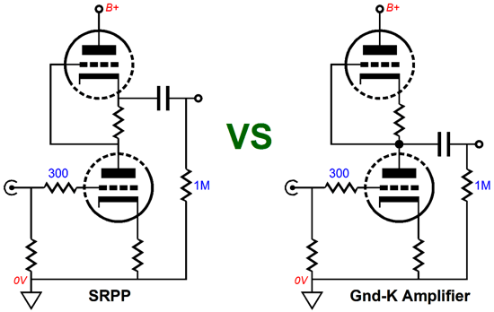
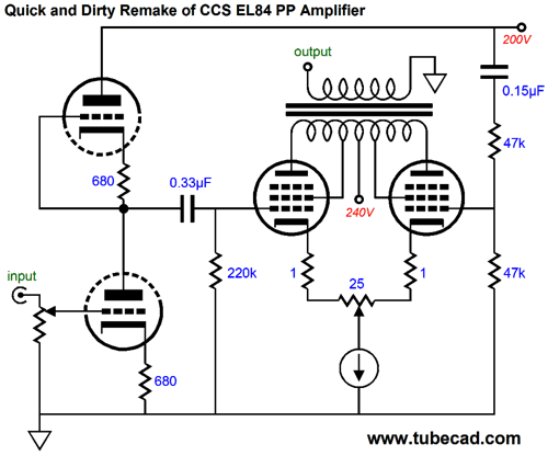
Perhaps you are old enough to remember the TV ad that showed French chefs being tested to see if they could tell the difference between real butter and margarine. They all proclaimed in outrageous French accents, "No dee-france!" or in English, "No difference!" What follows is an example of a gratuitous SRPP circuit. The following amplifier design must be causing a big stir out in tube land, as I have gotten at least three excited e-mails asking for my opinion. Working on the one-in-a-thousand rule, this means that there are at least 3,000 other tube lovers who are interested in the circuit.
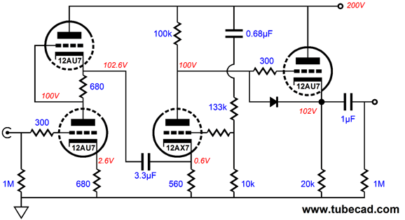
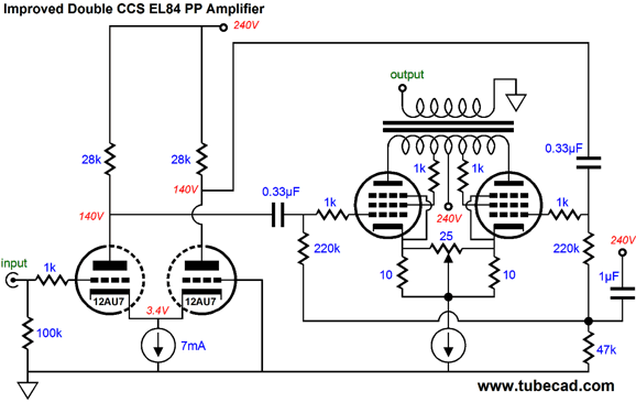
Bruce Heran's push-pull amplifier design forgoes the use of a phase splitter, relying on the pair of output tubes to do their own phase splitting with the aid of the constant-current source (an LM317). The SRPP input stage develops all the input signal for the output stage. The 25-ohm potentiometer sets the idle-current balance between output tubes. The constant-current source also auto-biases the output tubes. Okay, everything looks great, but does it work? It does, but how well? First of all, where are all the ABSOLUTELY essential grid-stopper resistors? Stray inductances combine with the tube's input capacitance, producing a resonant circuit, a dangerous outcome. Second, wouldn't a 12AY7 or 6N1P work better than the 12AU7/ECC802S, as they would provide much more gain? The 12AU7-based SRPP produces a gain of only 8.5, but the push-pull output stage requires twice the input signal that a balanced set of signals would deliver to the grids. In other words, more gain is needed, if 1V input signal is going to the drive the amplifier to full output. Third, and perhaps most importantly, why the SRPP stage? Where is the low-impedance load that it must work into? Surely, the 220k grid resistor does not count. Would there be any difference in performance if the 0.33µF coupling capacitor attached to the bottom of the 680-ohm Rak resistor, rather than at the top? I doubt it. The logic probably runs along the lines of: It looks cool, therefore it is cool. Possibly, but do not bet any money on it. In sum, this strikes me as a good example of a gratuitous SRPP design, but not an egregious one by any means. Moreover, the inclusion of the SRPP topology doesn't positively hurt the amplifier's functioning, rather it just represents a small failing to utilize all the potential latent in the input stage's two triodes, being more of a missed opportunity rather than a fatal blunder. In fact, the gratuitous inclusion of SRPP circuits strikes me as being as funny as an American affecting high-status British accent. The first change I would make would be to lose the SRPP affectation; second, include some Aikido design both to improve the PSRR, by giving the right output tube a better grid signal, a signal that isn't so clean! Unlike push-pull output stages that receive a balanced input signal, thereby allowing common-mode noise to fall out of the amplification, this output stage gets only an unbalanced input signal, which means that any power-supply noise riding atop the signal is treated as signal and amplified.
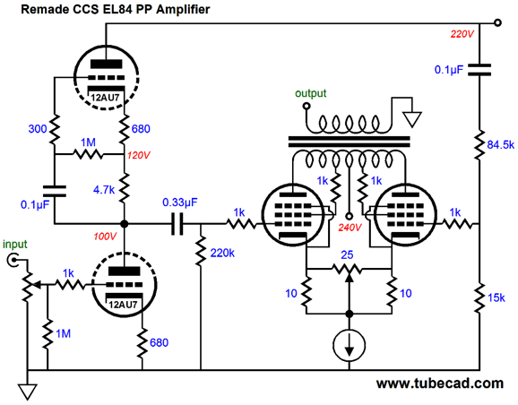
The grounded-cathode amplifier input stage will halve the ripple present at its connection to the 200V B+ at its output, so we must give the right output tube's grid the same amount of ripple, which will, in turn, then fall out of the equation, greatly improving the PSRR. Try it, you just might like it. The remaining problems, such as too little gain from the input stage and likelihood of oscillations will require something bit more complex. Unfortunately, what was so beguiling and wondrous about Bruce's original design was its staggering simplicity, in complete disregard of Einstein's famous dictum: "Everything should be made as simple as possible, but not simpler." This amplifier lives under the shadow of simpler. I have endeavored to retain as much of his original circuit, while bringing the circuit out into the simple sunlight. Three goals were set: less noise, more safety, and no oscillations. The SRPP stage only offered a gain of about 8.5, whereas the input circuit shown below delivers a gain of 14 and presents a PSRR figure 10dB better, -16dB vs -6dB. The input potentiometer's output is now shunted by a 1M resistor and the 25-ohm power potentiometer on the output stage now shares the CCS's current with the two 10-ohm resistors. Why? I fear and hate potentiometers. They go flaky, literally. If you take apart an old potentiometer, you often find bits of conductive paint littered about inside. They often lose contact; they cannot tolerate much DC current flow; and they often become noisy.
The added grid-stopper resistors stop oscillations. Never forget that while output transformers may stink at high frequencies (and very low frequencies), tubes are naturally high-frequency proficient devices. But as the grid presents so high an input impedance, any stray lead inductance can lead to high-frequency oscillations, which may not make it through the output transformer, but can overheat the output tubes and ruin the sound. Placing some pure resistance in series with the grid is the cure. Thus, non-inductive designs, such as carbon-composition or bulk-foil, are best for a grid stopper resistor. By the way, since the solid-state constant-current source was deemed sonically okay in the output stage, why not use one in the input stage as well? Here is what I have in mind.
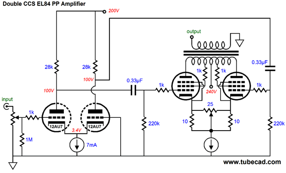
It is as simple as it is obvious. The phase splitter function belongs to the input stage now. The output stage still runs in class-A, push-pull. And although the gain from each output of the input differential amplifier is only 7, they effectively combine to create a gain of 14. Now, let's make the next move.
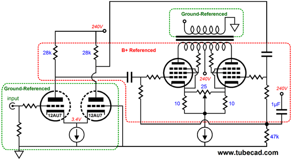
The addition of the 47k resistor and 1µF capacitor effectively makes output stage B+ referenced, which is a good thing, as the input stage offers a PSRR of zero, i.e. all the power-supply noise pours forth unimpeded. But as the output tubes see the CCS at their cathodes, not ground, the input differential amplifier's poor PSRR becomes a feature, not a liability.
Okay, I better stop here, before I go on several new threads. But before leaving the topic of Bruce's design, I want to stress that I am not really picking him or his design—well maybe just a tad. Actually, I could have picked hundreds of other gratuitous SRPP designs to pick on slightly; his was just handy. Indeed, one thought that came to me was that Bruce might a true wizard, as he might have purposely designed the most minimalist design he could get away with, so he could garner as many newbies as possible, filling them with awe and excitement at finally finding an amplifier circuit they could understand and build, knowing that if he revealed too complex a circuit he would lose most of his design's new adherents. Then, slowly he would make small, incremental improvements that gradually would lift his audience out of their darkness into the bright light of coherent design. Brilliant, just brilliant. If only I had the patience.
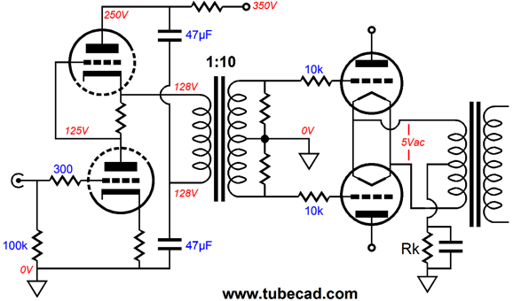
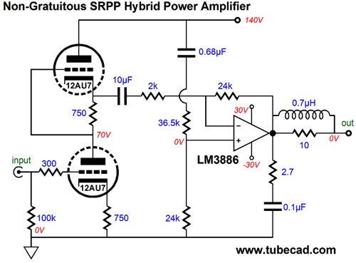
Non-Gratuitous SRPP Hybrid Power Amplifier A non-gratuitous-SRPP-hybrid design requires that the SRPP fulfills its intended function: delivering current into a low load impedance. In the following hybrid amplifier, the SRPP must drive a 2k load, which for a tube is low. Why not drive the solid-state amplifier's non-inverting input instead, as it is a high-impedance input? Most solid-state amplifiers deliver better performance when configured as inverting amplifiers. Why? well, if for no other reason, it keeps the input stage fixed and not swinging wildly about with the input signal.
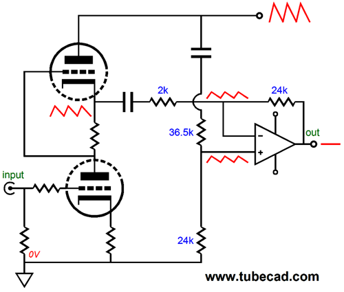
I was struck immediately by how this hybrid amplifier looked like something that I—and I alone—would design. Surely, 90% of amplifier designers would just ground the solid-state amplifier's non-inverting input; the remaining 10% would use the 24K to ground with a small capacitor bypass; but only I would use a two-resistor voltage divider to inject a portion of the high-voltage power-supply noise into positive input. What does this odd arrangement buy us? Enhanced PSRR is the answer. The SRPP input stage suffers from a fairly poor PSRR performance. But as we know how much B+ noise will leak from its output, we can anticipate its appearance and offer a countervailing sampling of the B+ noise to the solid-state amplifier, which results in a noise null at the solid-state amplifier's output.
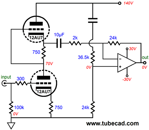
Shown above are the power-supply-noise relationships within this hybrid amplifier. The solid-state amplifier strives to establish identical voltages at its two inputs, which can only be brought about by having its output mimic ground in the absence of an input signal. But with AC input signals, the solid-state amplifier simply amplifies the SRPP's output signal. In DC terms, the 10µF coupling capacitor isolates the SRPP's high DC output voltage and the 0.68µF capacitor, which terminates the two-resistor voltage divider into the B+ connection, blocks the high voltage at the B+ connection. Thus, the solid-state amplifier can use all of its high open-loop gain to keep its DC offset low. In addition, the 24k feedback resistor and the 24k two-resistor voltage divider resistor help ensure a low DC offset voltage, as any input current drawn by the solid-state amplifier's inputs will match and fall out of the equation.
Shown above is the fleshed out hybrid amplifier. An LM3886 was specified, but many other chip amps could be used, such as the LM1875, LM3875, LM4780, OPA541, OPA548, OPA549, TDA7293, and TDA7294... The power supply can be as simple or as complex as you please. I would use one of my PS-6 kits, as it would develop both the ±30V rails for the solid-state amplifier and the 140Vdc rail for the SRPP tube.
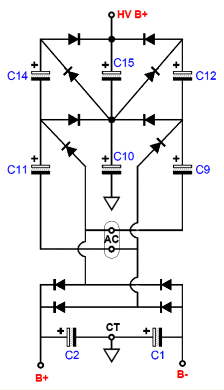
A power transformer that holds a 44Vac CT secondary powers the PS-6 and the three output voltages come out. The high-voltage rail is created the PS-6's voltage-quintupler circuit. If the bipolar rail voltages are ±40Vdc, the high-voltage output will be about 200Vdc. The heater voltages could either be stolen from the +30Vdc rail, with the two 12AU7 heater elements in series and in series a 120-ohm 5W power resistor, or taken from a small 6.3Vac or 12Vac heater transformer.
By the way, the PS-6 kit no longer comes with Nichicon 3,300µF audio capacitors; instead, due to many requests, it now comes with two Panasonic 10,000µF capacitors for the bipolar power-supply rail voltages.
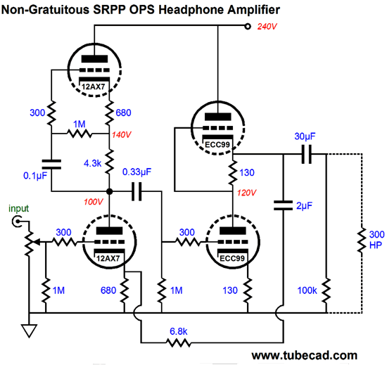
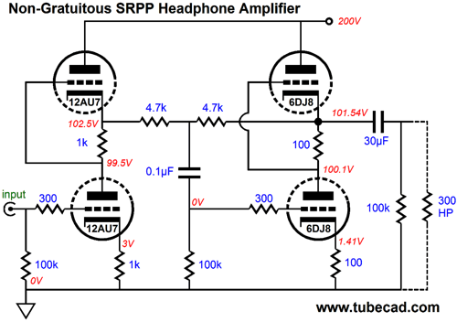
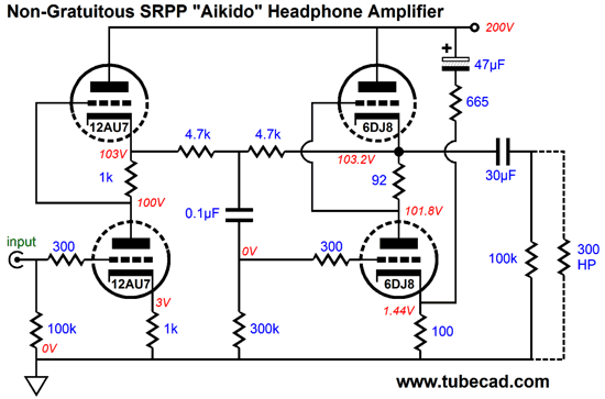
Non-Gratuitous SRPP Headphone Amplifier Rak = (rp + 2Rload) / mu and its brother Rload = (muRak - rp) / 2 must be fulfilled. This means that, for most triodes, a low load impedance must used. Well, as everyone knows, my Sennheiser HD650 300-ohm headphones are always eager to try a new tube headphone amplifier.
The 12AU7-based input SRPP stage works into a 4,700 load; the 6DJ8-based output SRPP stage drives the 300-ohm headphone driver. The two 4.7k resistors define a negative feedback loop, so the second SRPP stage functions as an inverting unity-gain buffer or a push-pull anode follower of sorts. The distortion is low for this circuit and balance between top and bottom 6DJ8 triodes is excellent. Still, I wasn't all that pleased with the -18dB PSRR figure. A regulated power supply would certainly help, but I would prefer a better PSRR figure even with a regulated power supply. Then it hit me, why not throw some Aikido magic at this circuit, much in the same way that I had done with the hybrid power amplifier design.
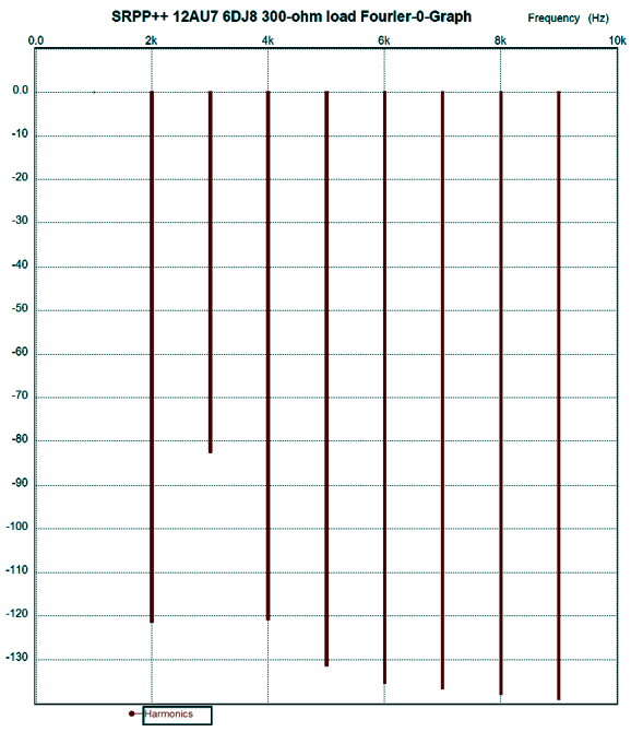
A sampling of power-supply noise is injected at the bottom 6DJ8 triode's cathode, not its grid, as you might expect. The reason behind this arrangement is that the ripple comes out inverted at the output, so non-inverting power-supply noise is needed to counter the inverted ripple. The 665-ohm resistor injects the desired amount of ripple into the cathode. With this "Aikido" technique in place, the PSRR figure improves by about 36dB, bringing the figure up to -54dB of PSRR. The SPICE simulations of this circuit are particularly fine, as the following Fourier graph shows for 1Vpk @ 1kHz into 300 ohms. Note that -80dB equals 0.01% distortion. Of course, reality is not likely to match SPICE. Why not? SPICE tube models assume a perfectly constant triode mu; reality differs. Still, SPICE does give a good predictive advantage, as an audio circuit that performs poorly in SPICE simulations is not going to perform better in reality. Why does SPICE give overly optimist results so often? SPICE assumes that all resistor, capacitor, and inductor values are 0.00000000001% on the mark and that none of these devices display any imperfections, such as a capacitor presenting any inductance or resistance, which real capacitors do. In reality, even a length of straight wire presents both inductance and resistance.
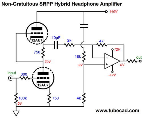
As you can deduce from the graph above, the idle current is a little over 14mA, which means that the maximum voltage swing into the load will be about 2 x 0.014 x 300, or 8.4Vpk. Plenty loud. What if you own 32-ohm or 50-ohm headphones? I would use different output tubes, such as the 5687 or ECC99 and many in parallel, say three ECC99 tubes per channel. Imagine eight tubes protruding through the top of the enclosure and an American V8 car medallion adhered to the front panel. Or, you could use a step-down output transformer. On the other hand... The SRPP hybrid power amplifier topology could be used to create a fine hybrid headphone amplifier, along the same lines as the SRPP hybrid power amplifier.
Note the ±12V rail voltages for the OpAmp. Yes, OpAmp, such as the LT1210, LT1364, OPA2107, or OPA637... Also note this design uses different two-resistor voltage divider values and a 4k feedback resistor, not a 24k resistor. Now the remaining question is Where could I get a power supply for this hybrid headphone amplifier circuit? Oh, that's right, the PS-15. What was I thinking?
Next Time
For those of you who still have old computers running Windows XP (32-bit) or any other Windows 32-bit OS, I have setup the download availability of my old old standards: Tube CAD, SE Amp CAD, and Audio Gadgets. The downloads are at the GlassWare-Yahoo store and the price is only $9.95 for each program. http://glass-ware.stores.yahoo.net/adsoffromgla.html So many have asked that I had to do it. WARNING: THESE THREE PROGRAMS WILL NOT RUN UNDER VISTA 64-Bit or WINDOWS 7 & 8 or any other 64-bit OS. I do plan on remaking all of these programs into 64-bit versions, but it will be a huge ordeal, as programming requires vast chunks of noise-free time, something very rare with children running about. Ideally, I would love to come out with versions that run on iPads and Android-OS tablets.
//JRB |
I know that some readers wish to avoid Patreon, so here is a PayPal button instead. Thanks. John Broskie
Kit User Guide PDFs
E-mail from GlassWare Customers
High-quality, double-sided, extra thick, 2-oz traces, plated-through holes, dual sets of resistor pads and pads for two coupling capacitors. Stereo and mono, octal and 9-pin printed circuit boards available.  Aikido PCBs for as little as $24 http://glass-ware.stores.yahoo.net/
Support the Tube CAD Journal & get an extremely powerful push-pull tube-amplifier simulator for TCJ Push-Pull Calculator
TCJ PPC Version 2 Improvements Rebuilt simulation engine *User definable
Download or CD ROM For more information, please visit our Web site : To purchase, please visit our Yahoo Store: |
|||


| www.tubecad.com Copyright © 1999-2014 GlassWare All Rights Reserved |