| John Broskie's Guide to Tube Circuit Analysis & Design |
18 April 2015
Updated Aikido LV and 12Vac Aikido PCBs
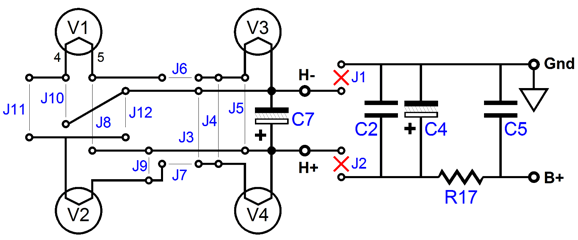
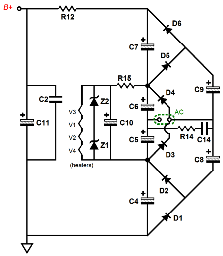
The Aikido-LV got the bigger change, as it can now either use a single DC voltage, say 48Vdc, to power both the tubes and the heaters, assuming four 12-volt heaters in series, or it can use two power supplies, a high-voltage one, say 48Vdc to 100Vdc, and a low-voltage one, say 12Vdc. In other words, you now have options that you didn't have before. Here is the heater arrangement schematic.
Yes, that is a lot of jumpers, but you only have to figure it out once. If you want to put all four heater elements in series, then use jumpers J6, J7, and J11. If you want to put all four heater elements in parallel, then use jumpers J5, J8, J9, J3; and if you wish to use the B+ voltage to power this string of four heater element, use jumpers J1 & J2 as well. Okay, why did I make this change? I know that many customers were buying the Aikido LV and using it with four 6DJ8/6922/E88CC tubes and with a 24Vdc power supply. I have tried this configuration and I wasn't pleased. Or rather, I was much more pleased with the same 24V power supply powering four 6GM8/6N27P/ECC86 tubes. No doubt the four 6DJ8 tubes sounded better than did the solid-state line stage that these customers had been using prior, else they wouldn't have been so pleased with the improved sound. But believe me, those same four 6DJ8 tubes will sound much better with 48V to 100V as the B+ voltage. Well, with the new configuration, we can use a 48V wallwart power supply for the B+ and a 12V wallwart power supply for the heaters. (Tubes V1 & V2 can have their heaters in series, while tubes V3 & V4 do the same, so a 1A, 12V power supply can be used with 6DJ8 tubes; just use jumpers J4, J8, J11 and J9.)
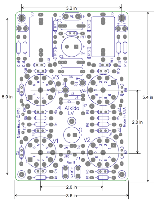
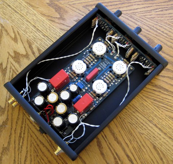
Indeed, one could build a relative high-voltage Aikido with the new Aikido LV PCBs, yet the boards are small, being only 3.6 inches by 5.4 inches big. I can imagine an Aikido LV being fit within an existing CD player, with two DC power jacks placed on the back panel, so 12V and 48V power supplies can be attached to power the Aikido stage. (Most modern CD players are mostly empty. If you do not believe me, take a look inside.) The Aikido 12Vac PCB got a smaller change: its heater string is now protected by two zeners in series.
One big problem with 12Vac and 18Vac wallwart transformers is that they offer poor voltage regulation, with the danger of applying too much heater voltage.
Well, the two 5W zeners take care of that problem, as they limit the maximum voltage across the heater string to either 24Vdc or 50Vdc.
Single-Ended Power Amplifiers
Speaking of single-ended tube power amplifiers, one reader wanted to know why I was seemingly so down on the four-300B OTL amplifier that puts out 1 watt, which was designed by Bruce Rozenblit, and which I covered in my review of Bruce's book, Tubes and Circuits.
An odd e-mail; it was almost as if the writer were pleading with me, beseeching me, entreating me to endorse the project, so that he could have permission to build it. Shouldn't he have asked for Bruce's permission, or his wife's, not mine? (Hi Honey, you know that money we were putting away for the kid's college education, well I spent it on eight NOS 300B tubes and some magic beans...) I got the feeling that the reader eagerly wanted to build this OTL, but was worried by my lack of enthusiasm. What answer can I give other than: if you have gobs of cash to burn and the urge to build a 1W stereo amplifier that uses eight super expensive 300B output tubes, four per channel, go for it and God bless your efforts. This is America (or Europe or...) after all, where men are men and soldering irons are hot. Very strange, but not uncommon, alas. I was once at a listening session with a few close friends and we all felt that something was off the mark. I made the observation that the midrange sounded out of phase. I recommended that the owner of the $$$ speakers take a screw driver and remove the midranges and flip the phase to hear if I was on to something. The completely dismayed speaker owner told me he could never do that; so, I told him to get a screw driver and I would it for him. Finding a screw driver was not the problem; the problem was that the designer of the speaker would not approve of anyone flipping the phase his midranges. My reply was that since he had bought he speakers over five years ago and since they were now long out of warranty, who cares whether or not the designer might approve, even if he were in the room with us; indeed, if he were in the room with us, he might have recommended flipping the phase himself. My friend was adamant; he could never go against the designer's wishes. Well, about ten years later, while I was attending a stereo show, I ran into the very same speaker designer and I told him this story. He had a good laugh and admitted that, at the time that he designed his speaker, he was much more of a fine woodworker than a speaker designer; and that at the time he hadn't come close to understanding the subtleties of crossover design, which he now did (he now advocates steep digital filters); and that I was most probably right, the midranges were probably out of phase. Do not get me wrong here. Always give a circuit or speaker a fair hearing. Build a circuit up just as the designer wanted, using his part values and part types. Then listen for a week or two; if unhappy, then and only then, make alterations. And only make one change at a time. Okay, back to 300B OTL amplifiers, I asked the reader what he thought of my Somersault OTL variation, which would quadruple the output power, but I received no reply. Perhaps that was a leap too far.
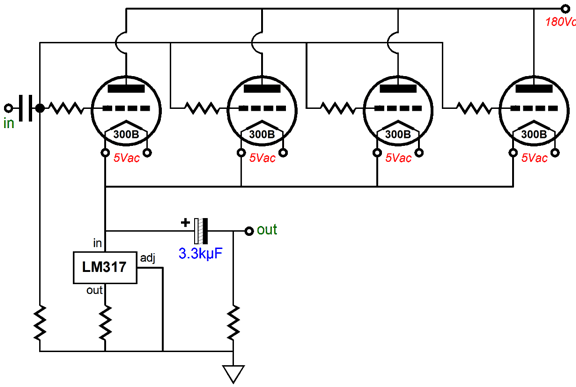
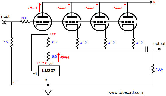
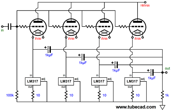
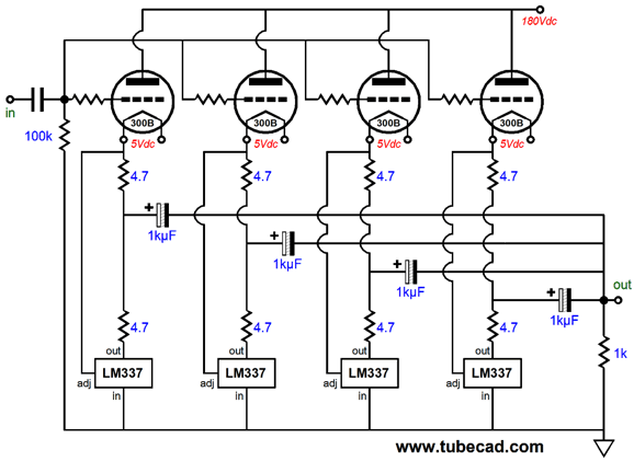
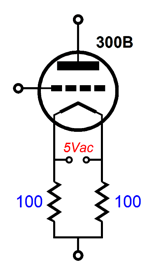
Even if we stick to Bruce's original design concept, we can make some improvements. Here is what I would do: give each 300B output tubes its own 5Vdc filament power supply and its own LM317-based constant-current source and its own coupling capacitor to the output.
Now, each 300B can bias up to its own grid-to-cathode voltage. In addition, even if only one 300B is plugged into its socket, it will not be overtaxed, as its own constant-current source limits it conduction to 125mA, not the 500mA that the single constant-current source would impose. Note how each output coupling capacitor is only 1kµF, not the 3.3kµF in the original. Effectively, all four are in parallel, so their combined capacitance is 4kµF. Moreover, the ESR and series inductance in much lower due to the four being in parallel. (Yes, of course, each could and should be bypassed by a quality film capacitor.) We could apply the same logic to the my Somersault circuit, which is a push-pull, class-A topology, which doubles the output current swing and, thus, quadruples the power output, from 1W to 4W. (By the way, I have received some e-mail that proclaims that the original 300B OTL amplifier delivers 1.5W, not 1W. Really, when were the laws of physics revoked and why didn't anyone tell me? In a single-ended OTL amplifier with a constant-current-source load, the peak symmetrical output current is equal to its idle current; period. Therefore, 500mA equals 500mA, which into an 8-ohm load equals 1W, Wattage = I² x Rload/2; in this case, 1W = 0.5² x 4. On the other hand, if you are willing to tolerate an asymmetrical output signal, distortion-filled, then any single-ended power amplifier can put out more distorted power than its nominal rating. Just as if you wish you were taller, so you jump up and down while your height is being measured—isn't that how they do it in Hollywood?)
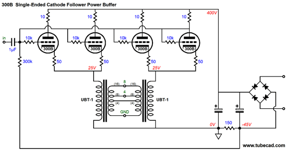
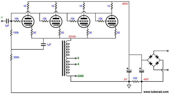
Each 300B get its own push-pull impedance multiplier circuit and we get 4 mighty watts. Still, I would do something vastly different with four 300Bs. For example, all four could be used in a cathode-follower output stage with two One Electron UBT-1 single-ended transformers in parallel, with the 16-ohm output taps in parallel becoming 8-ohm taps; the 8-ohm taps, 4-ohm taps. Such an amplifier could easily put out 30W and deliver very low distortion and low output impedance.
No doubt many are puzzled by the 10-ohm plate and 50-ohm cathode resistors; don't be. Tubes are high-frequency devices, which makes them susceptible to ultra-high-frequency oscillations. The 10-ohm anode-stopper resistors. impose some simple resistance to the plate circuit, which inhibits oscillations at the plate, which can result from excessive lead inductance. The 50-ohm cathode resistors inhibit current hogging and help linearizes the 300B tubes. Mind you, they do not sell 50-ohm resistors; in fact, they are actually two 100-ohms resistors configured like this.
Each 300B gets its own 5Vac winding and its own (effectively) 50-ohm cathode resistor. Another possibility is an autoformer-based 300B single-ended. cathode-follower output stage. What's an autoformer? An autoformer is much like a transformer, but less and more. It only holds one winding, with at least one tap (often many taps), which is certainly less. Like a transformer, however, it reduces voltage swing and increases current swing; and it magnifies impedance, while delivering same amount of power out that it receives. Unlike a transformer, however, an autoformer does not provide electrical isolation. In other words using an autoformer at a triodes plate, assuming the plate is at some high B+ voltage, can be lethally dangerous; but used at its cathode, assuming the cathode is at ground potential, can be perfectly safe. The autoformer's "more" in comes in improved performance, such as wider bandwidth and less phase shift and reduced insertion losses.
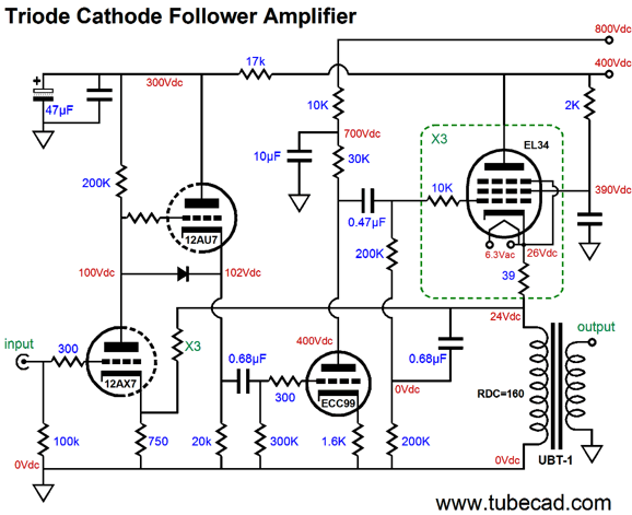
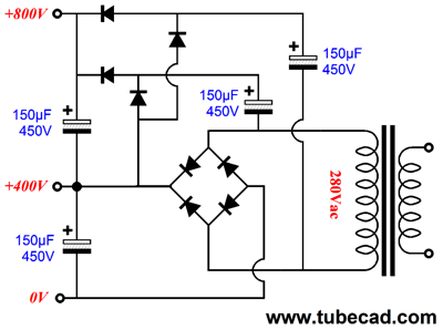
Great, where do I buy one? One possibility is to hunt down the makers of distributed sound systems transformers and autoformers, such as Edcor. Indeed, if you contact the nice folk at Edcor, they can custom make you one. Tell them you need to put out 50W and present 800 ohms from end to end. After paying thousands of dollars for your NOS WE 300B tubes, you will be pleasantly surprised how reasonable the Edcor prices are. Of course, such a cathode-follower output stage will require huge input voltage swings. Time to re-read my last post, which shows many ways to drive a cathode-follower output stage, such as the following.
The CCDA input stage drives the ECC99, which gets its own 800Vdc power-supply rail. At this point, many readers abandon all hope and interest. "It's own 800V power-supply rail! How would I ever accomplish that?" they asked themselves dejectedly.
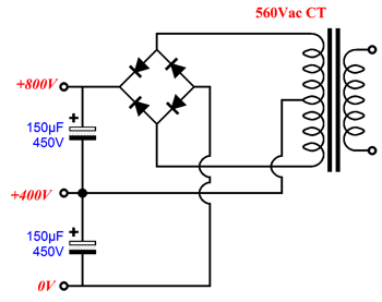
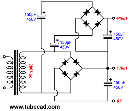
A center-tapped power transformer can be used, such as the one shown above. We can even use a non-center-tapped power transformer, as shown below.
As I look at this schematic, I realize that not only is layout going from right to left, a no no, but that the second bridge rectifier quartet does not look like the bottom one.
How's that? Is it easier to see what is going on in this redrawn schematic? Well, remaking the four-300B amplifier and other single-ended designs led me back to an old design idea, the super triode.
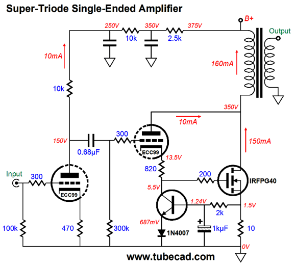
Single-Ended Super-Triode Amplifiers
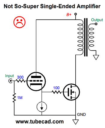
The answer to our dreams was the wedding of the triode to a solid-state power device, such as a power MOSFET or bipolar transistor; and like most marriages, where one partner has more control than the other, usually the weaker one ruling over the stronger one, in this marriage, the triode is running the show.
In fact, the triode draws a fairly constant current, while the MOSFET swings big current flows, as the constant-current source in series with its cathode, limits the triode's conduction. Yes, it looks something like a Darlington transistor arrangement; and it would be a Darlington circuit of sorts, if we made the following mistake.
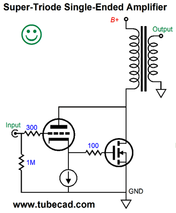
Here the triode only serves to provide the needed bias voltage and drive current for the power MOSFET. But the triode is not in control of the MOSFET. For example, the MOSFET's output impedance will approach infinity and its gain will equal its transconductance against the load impedance. In contrast, the following amplifier uses a super-triode, as the triode superimposes its characteristics on the MOSFET.
The triode is behind the steering wheel. If we hold a triode's conduction constant, then the plate is mu times less effective than the grid in controlling current flow through the triode. For example, if we increase the grid-to-cathode voltage by 1V, then the plate voltage must fall by mu times to maintain the same current flow. Well, in the above circuit, the triode is held to a fixed idle current, so the MOSFET's current conduction must observe the triode's amplification factor (its mu or µ) to maintain the fixed triode current flow. In other words, the super-triode, which consists of both the triode and MOSFET, will exhibit a voltage gain equal to the mu of the triode. Use a 6SN7 and the gain will be 20; use a 6DJ8, a gain of 33. (We assume that the load resistance allows this amplification to obtain.)
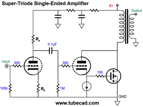
Wait a minute, John; what happens if the triode's cathode voltage isn't high enough to turn on the MOSFET; or too high, so the MOSFET over conducts and melts? The answer is we need an auto-bias circuit to set the MOSFET's idle current flow, such as the one shown below.
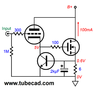
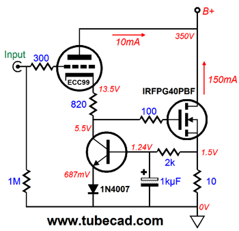
The triode still sees a steady current flow, as does the MOSFET. If the MOSFET draws too much current, the NPN transistor pulls down the cathode voltage and the MOSFET's conduction. If the MOSFET draws too little current, the NPN transistor releases its downward pull on the cathode and the MOSFET's conduction increases. Here is a design example.
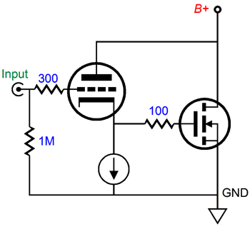
If we limit the ECC99's current conduction to 10mA, we will have to set a cathode voltage of 13.5Vdc, which would set the MOSFET on fire. So, we place a cathode resistor in series with the transistor and cathode. In this case, the MOSFET receives its needed gate voltage and the triode gets its needed cathode voltage. Because the transistor approximates a constant-current source, the 82-ohm cathode resistor sees a fixed voltage drop, much as if the resistor had been replaced by a battery. Let's look at the complete amplifier with the auto-bias circuit in place.
A single ECC99 provides all that we need. The IRFPG40 is a 1kV, 150W N-channel, enhancement power MOSFET that cost about $8 each. I only specified it because I have a SPICE model for it. (I would actually look into getting some Sanyo high-voltage MOSFETs, as they tend to present much less input capacitance. Moreover, even with a 150W rating, one MOSFET is not likely to work, as several will likely be needed.) I fear that I will have to stop here, as my day is running out. Believe me, I will have much more to say about super-triode designs next time. Be sure to check out all the PCBs and kits that are now back in stock at my GlassWare-Yahoo store. (The Unbalancer PCBs are selling fast, so be warned.) Thanks.
Next Time
User Guides for GlassWare Software Since I am still getting e-mail asking how to buy these GlassWare software programs:
For those of you who still have old computers running Windows XP (32-bit) or any other Windows 32-bit OS, I have setup the download availability of my old old standards: Tube CAD, SE Amp CAD, and Audio Gadgets. The downloads are at the GlassWare-Yahoo store and the price is only $9.95 for each program. http://glass-ware.stores.yahoo.net/adsoffromgla.html So many have asked that I had to do it. WARNING: THESE THREE PROGRAMS WILL NOT RUN UNDER VISTA 64-Bit or WINDOWS 7 & 8 or any other 64-bit OS. One day, I do plan on remaking all of these programs into 64-bit versions, but it will be a huge ordeal, as programming requires vast chunks of noise-free time, something very rare with children running about. Ideally, I would love to come out with versions that run on iPads and Android-OS tablets.
//JRB |
Kit User Guide PDFs
And
High-quality, double-sided, extra thick, 2-oz traces, plated-through holes, dual sets of resistor pads and pads for two coupling capacitors. Stereo and mono, octal and 9-pin printed circuit boards available.
Designed by John Broskie & Made in USA Aikido PCBs for as little as $24 http://glass-ware.stores.yahoo.net/
The Tube CAD Journal's first companion program, TCJ Filter Design lets you design a filter or crossover (passive, OpAmp or tube) without having to check out thick textbooks from the library and without having to breakout the scientific calculator. This program's goal is to provide a quick and easy display not only of the frequency response, but also of the resistor and capacitor values for a passive and active filters and crossovers. TCJ Filter Design is easy to use, but not lightweight, holding over 60 different filter topologies and up to four filter alignments: While the program's main concern is active filters, solid-state and tube, it also does passive filters. In fact, it can be used to calculate passive crossovers for use with speakers by entering 8 ohms as the terminating resistance. Click on the image below to see the full screen capture.
Tube crossovers are a major part of this program; both buffered and un-buffered tube based filters along with mono-polar and bipolar power supply topologies are covered. Available on a CD-ROM and a downloadable version (4 Megabytes). |
||


| www.tubecad.com Copyright © 1999-2015 GlassWare All Rights Reserved |