| John Broskie's Guide to Tube Circuit Analysis & Design |
23 May 2015
Something New at the GlassWare-Yahoo Store
Back in Stock
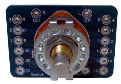
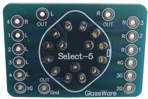
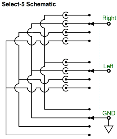
Note how each signal source's ground is selected along with the left and right signal "hots." As you select one signal source, you also select its ground. This means that the other three signal sources grounds do not attach to your system, making them electrically independent; thus, preventing them from interacting with each other. This can be critical, if one of the signal sources is a TV, as the CATV ground is often electrically dirty and creates huge hum headaches. The Select-5 input signal source selector switch & PCB is once again available now at the GlassWare-Yahoo store for an incredibly inexpensive price of $18.
Moving-Coil Pre-Preamplifiers
If you have grown bored of music, perhaps, just perhaps you have only grown bored with digital recordings. I know it sounds crazy, but there just some profoundly right about analog tape and LP playback. I mention both types purposely, as I once thought that it might be the very hateful ticks and pops of LP payback that actually improved the listening experience, as it forced the brain to attend the music more carefully, as those tics and pops were real, live, and unpredictable sonic events, which could not be ignored as canned sonic events as dead as the flowers printed on old wallpaper. But Tapes do not tick or pop, although they can wow, flutter, and hiss; yet, open-real tape playback shares the LP's magic and often excels it. By the way, I have been fighting this conclusion for decades, as digital music storage and playback is just so much easier, particularly now that we have computer-based systems, which allow for all the benefits of database music management, streaming music from room to room, and portable-device music playback. In contrast, LPs play for less than half an hour a side and even skipping a track requires a lot more effort, as does cleaning the record and stylus. Thus, records must offer a great deal to beat the competition and they do. Over the past three decades, on several occasions, friends have sat me in their listening chair and played a favorite record for me; afterwards, I was asked if I didn't acknowledge that there was something magical going on with the LP's playback. Shamefully, I usually made some snide comment about the surface noise, as I felt as uncomfortable as a man who must answer some husband's insistent pleadings that his plain-Jane wife is altogether lovely. Nonetheless, I have several classical LPs that I would never play to impress audiophiles, and whose first sonic impression is that of a staid and unforgivably dull sound, which yet produce deep emotional responses within me. A sonic paradox of the first order. The only CDs I own that always deliver some strong emotional response are, first, a 1980's London CD of Dvorak's Quintet for Piano and Strings no 2 in A major, Op. 81/B 155 played by Vienna Philharmonic Quartet with Clifford Curzon on the piano, which was recorded in 1962 and undoubtedly on all-tube equipment. I love this CD.
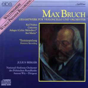
The second is an EBS CD of Max Bruch's Complete Works for Cello & Orchestra, with Julius Berger playing the cello and Antoni Wit conducting the Polish Radio Symphony Katowice.
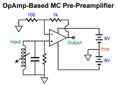
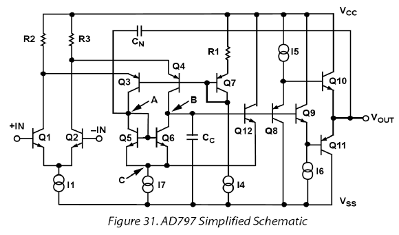
Yet, I own well over 1,000 CDs, so the percentage of magic to mundane is dismally puny, no where near the LP's higher ratio. I know that many will instantly tune at the mention of classical music, so I will mention the following. Take any Carpenters LP and its equivalent CD and perform a sonic shootout. Which medium won? I know where I would place my bet. Here's the thing: I claim not to like the Carpenters, but when I play one of their LPs I become a huge fan. What a voice Karen had! Thus, LPs are like a magical bridge to musical appreciation. Countless times I have attended LP spinning sessions with friends, where we listened in rapt enjoyment of music we supposedly hated. To be frank, this has happened a few times with CD playback, but the effort was an uphill one. In other words, I have had LPs on my mind and ears. Soon, all too soon, I expect my old Dynavector DV-10X5 (a high-output MC) to give up the ghost. And as getting it re-tipped costs only a few twenties less than buying a new one, I will probably move on to another cartridge. One thought is that I would like to play with a low-output moving-coil (MC) cartridge, which will entail my designing and building an MC pre-preamplifier. Why? Wonderful as vacuum tubes are, they aren't very good in super-low-noise applications, wherein mircovolts are amplified. A medium-output MC cartridge puts out about 0.5mV, compared to the moving-magnet's 5mV of output. On the other hand, if given a few millivolts of input signal, they can take over. The first idea I had was to just use a low-noise OpAmp, such as the AD797, which mercifully is still available in through-hole, 8-pin, DIP format and relatively cheap at less than $10 each.
All that is needed are two OpAmps and two 9V batteries and few capacitors and resistors. Not bad.
No doubt there are now quieter OpAmps for sale, but many are no longer available in anything other than a surface-mount package, which is pain to solder. Another possibility is to buy a high-quality step-up transformer, which will not be inexpensive, but does offer an elegant solution.
Now that I have exhausted the obvious solutions, I will move on to the less-obvious approaches. We could use a single transistor in a simple common-emitter (i.e. grounded-emitter) amplifier topology.
A single BC550 NPN transistor and 12V power supply and we are ready to go. Or are we? First of all, coupling capacitors, front and rear, will be needed, which is a small pain. The bigger pain is the poor PSRR figure this pre-preamplifier exhibits, almost no power-supply rejection that its output; thus, the unhappy face. (Toshiba makes a super-quiet NPN transistor, the 2SC3324, but it only comes in a surface-mount package.) Do not fear, I will get to the two diodes. They are there as protection devices, as they limit the maximum output voltage swing to +/-0.7V or so. At start-up and shut-down, we do not want big output voltage swings to upset the phono stage and power amplifiers. Ideally, schottky diodes would be used, as they offer a lower conduction voltage. Putting on a happy face requires a bit more work and quite a few more parts, as shown below.
The same BC550 NPN transistor is used and the same gain of 10 (+20dB) is realized, but the PSRR is far improved. In addition, only the output coupling capacitor is needed. The assumption here is that the bipolar power supply offers equal, but out of phase, ripple on the positive and negative rail, which allow the Aikido move of using the two-capacitor AC voltage divider to inject the right amount of ripple into the BC550's emitter to null the ripple at its collector. This circuit offers low noise and a highly valued single-ended distortion harmonic structure. We can lower the transistor noise contribution by a factor of two—a -6dB improvement—by using four BC550 transistors in parallel, as shown below.
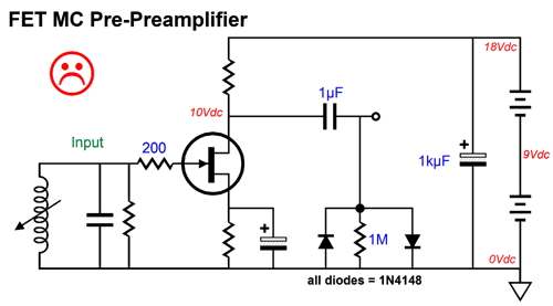
Wait a minute, John, are not FETs both quiet and more tube like? Well, they can be both, but they, too, also run into problems; in addition, they far more expensive than the comparable transistors and not as quiet as the quietest transistors.
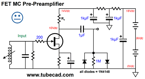
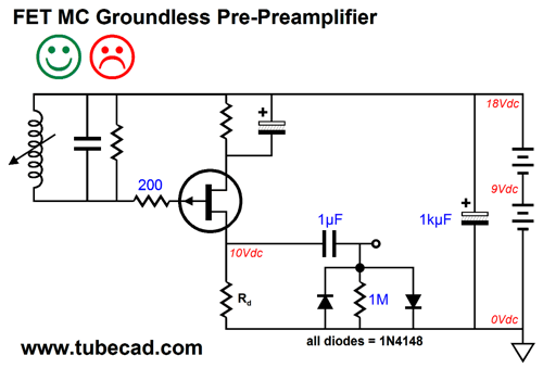
The above FET-based pre-preamplifier suffers from the same poor PSRR as the first transistor-based amplifier did. We could go the same Aikido, bipolar-power-supply approach, or we could just try reducing the power-supply noise at its source.
Above, we see two cascading RC filters employed to reduce power-supply noise. We could also use a well-regulated power supply. Still, it would be an up-hill battle. Do we really need to worry, if actual batteries are used? A good question. Batteries do give rise to noise, albeit not much. The bigger the battery, the less the noise, as the lower the effective series resistance, the lower the noise. Unfortunately, the tiny battery cells in a 9V battery are not nearly as quiet as a much bigger Ni-CD AA battery, which boasts an impressively low internal resistance. So, twelve 1.5V Ni-CD AA batteries would be needed in place of two 9V batteries. See Measurement of voltage noise in chemical batteries for more information. Moreover, many hate batteries and would opt for a 18V switcher wallwart power supply, which regularly put out about 500mV of ripple. Or, we could design a circuit that offered good PSRR from the start.
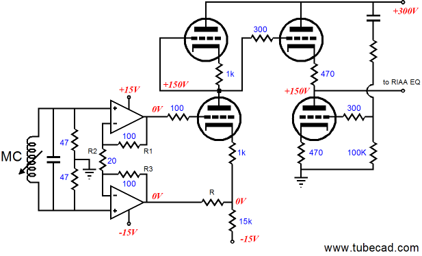
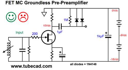
We have replaced the N-channel FET with a P-channel FET. And the cartridge is no longer "grounded" to ground. Think about it: a cartridge's coil is wonderfully free-floating device and presents a great balanced signal, as the impedance is equal from each lead. That we do not take advantage of this feature is sad. Sadder still, some cartridges (and tonearms) come with pre-grounded coils. Speaking of balanced amplification, be sure to check out blog post Number 120, where you will find schematics like the following:
While you are at it, check out Number 146, where you will find many interesting hybrid phono stages. My most quick-witted readers, such as Ziggy of Hiend-audio.com, will ask: Why cannot we use a the N-channel FET and move the ground to the top of the circuit? We can, if the coil is truly free-floating.
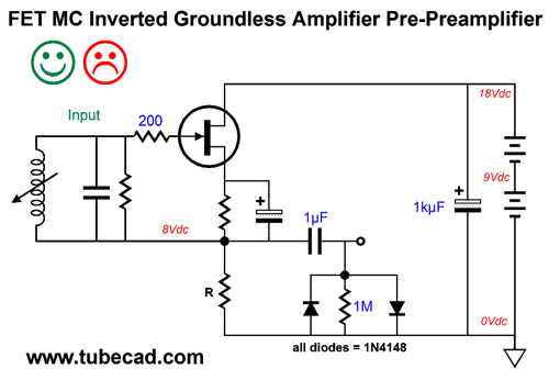
Well, there is a third option, which does not invert the phase at its output: the inverted amplifier.
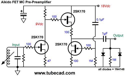
The cartridge's coils are not grounded to ground or the B+ connection, but float with the amplified signal. How is this possible? The FET has no idea what you are up to or what use it is intended for, as it only "knows" what voltage relations exist between its drain, gate, and source. As its gate becomes more positive relative to its source, the FET's current conduction increases. Conversely, as its gate falls in voltage, the FET conducts less current. The load resistor R sees the varying current flow and develops a corresponding altering AC signal that can far exceed the signal seen at the gate. In a word, amplification. Once again, this circuit will only work if the coil is truly free floating and not grounded; thus, the happy and unhappy faces. Another possibility is to build a FET-based Aikido, such as the one show below.
The only big problem we might face is too much gain, as we only about +20dB (or times 10), which explains why the input FET's source resistor is not bypassed by a capacitor. The 2SK170 may not be the best choice here. Such a pity that the Toshiba 2SK146 and 2SK147 are no longer made. The following, and last solid-state, design "grounds" the coil at ground and offers a good PSRR figure and fixed gain that is set by the ratio between two resistors. In SPICE simulations, this circuit performs very well indeed.
The PSRR is good, but not stellar. Thus, I attempted to improve it by cascoding the FET with an NPN transistor; the results were mixed. While the PSRR did improve, the harmonic structure worsened, losing the very strong single-ended signature, where the 2nd predominated and the 3rd was greatly suppressed. Okay, enough of solid-state designs; we now move on to tube-based MC pre-preamplifiers.
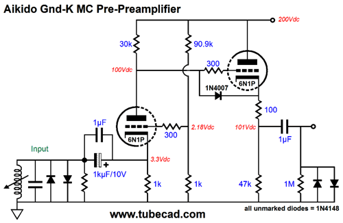
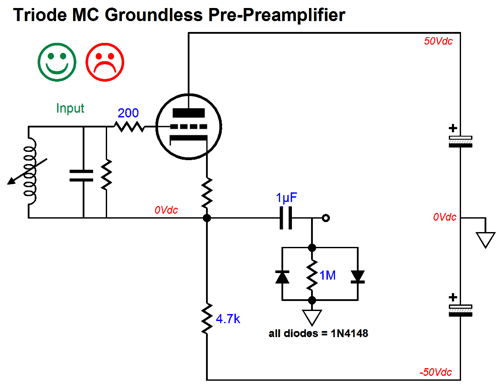
Tube-Based MC Pre-Preamplifiers Tube-based MC pre-preamplifiers are certainly possible, but not easy. Our goals are super-low-noise, flat-frequency-response amplification of only +20dB (times 10) capable of driving a 47k load resistance. Interestingly enough, unlike 40dB phono stage, an MC pre-preamplifier's low gain becomes an issue, as most phono preamp triodes, such as the 6DJ8, 6N1P and 12AX7 offer far too much gain due to their high amplification factors. Moreover, Miller-effect capacitance is not a problem, as most MC cartridges welcome a heavy capacitive load. (I have seen µF being used to quell high-frequency chattering.) Precisely because so many will assume that I will begin with a classic Aikido topology I won't. Instead, let's begin with an Aikido version of the grounded-grid amplifier.
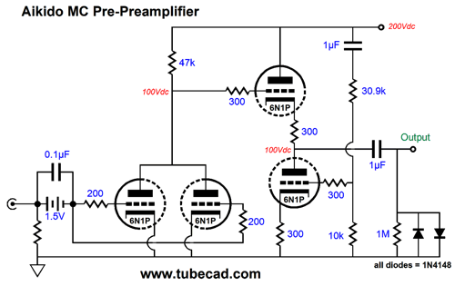
I have covered this circuit many times before, so I won't go into all of the details, just some of the more important ones. The 6N1P is a Russian tube that is based on the American 6BQ7A, I believe. It is not the 6DJ8's twin, as many falsely believe, as its heater draws 600mA compared to the 6DJ8's 365mA; its mu is 35, versus 33; and its gm is 3.5mA/V, versus 12.5mA/V. What it does offer is often very low noise. I would love to know how this was achieved, as you might expect noise to be simply the inverse of gm; in other words, the higher the transconductance, the lower the noise. My guess is that the cathode surface is specially treated and that it's not using a grid frame results in a less microphonic tube. Because many most MC cartridges require a low load resistance, the grounded-grid's low input impedance will not burden the cartridge in the way t would certainly drag down a moving-magnet cartridge. Protection diodes were added to the input and output, as we want to limit the maximum discharge voltage across the MC cartridge. The input coupling capacitor must be large in value, say at least 10µF. (1kµF is shown and it is probably far too excessive, as 47µF should be enough.) An electrolytic capacitor is show in the schematic, but I would actually use a non-polarized electrolytic capacitor from Panasonic instead, as they sound quite good. The 1n4007 protects the cathode follower triode at start up, when the tube is cold and not conducting, as it limits the maximum positive grid-to-cathode voltage to about 0.7V, not the full 200Vdc of the B+ voltage, which would be present in the diode's absence. The two-resistor voltage divider made up from the 90.9k and 1k resistors injects a small portion of the B+ ripple into the grid of the input triode, which thereby creates a power-supply noise null at the plate. Magic. Note how no capacitor was need to terminate this two-resistor voltage divider, as we welcome the DC offset, as it allows us to use a higher-valued cathode resistor. Another approach would the more conventional Aikido:
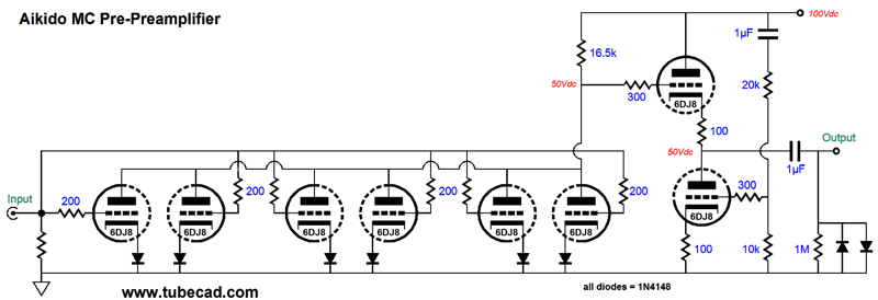
The same 6N1P tube is used throughout and the two input triodes are placed in parallel, which slightly lowers their noise. A 1.5V battery is used to bias the input triodes, so no cathode resistors are needed. Don't I worry about the battery's noise contribution? Yes, in fact, I do. One thought is that since the battery supplies no current, it may prove much quieter, as it is doing no real work. Another variation the Aikido is to use many input triodes in parallel.
Unlike the conventional Aikido, wherein the first stage halves the B+ ripple at its output, the AC voltage division is closer to only 30%, so the second stage has less work to do scrubbing away the ripple from its output. The six parallel triodes contribute less noise than a single 6DJ8 triode would. Why? In general, tube noise is mostly uncorrelated, which means random and unique, unless there is in-phase hum or microphonics present in each triode, so the individual noise contributions tend to average out, as positive noise signal meets negative noise signal, while the common signal gets added together. Here is a crazy analogy. You are standing in a hallway in a college dorm and each of the ten rooms presents an open door and within each room plays the same radio and TV and web broadcast simultaneously: Aliens have arrived from outer space, landing in Liechtenstein and are conversing with Prime Minster Adrian Hasler, whom the aliens deem the most important world leader. (It has something to do with his likeness to the father in the old TV show, Married with Children, which the aliens deem our finest cultural accomplishment so far.) Although within each room there is much rumbling and muttering, the broadcast is more readily heard emerging from the ten rooms than if a single room were playing the broadcast on its own, along with its solo random exclamations of amazement. The ten-room random "Oh my Gods" and "No Ways" and "We're doomed!" utterances cannot compete with the ten-room unison sounding of the same broadcast message. On the other hand, if all the room's occupants uttered in unison, "Oh my God, no way!" then hearing the ten rooms would be just as noisy as hearing one room. With uncorrelated yammering, our signal to noise ratio will improve by the square-root of the number of rooms playing the same broadcast, as ten room's uncorrelated mumbling's air compression meets air rarefaction, largely canceling. For example, four rooms will be -6dB quieter than a single room. Well, the same holds true for triodes. At the same time time, four 6DJ8s per channel is a lot tubes. In contrast, lets try to getaway with just one triode per channel.
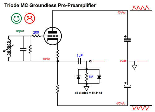
The assumption here, just as it had been in the earlier solid-state version, is that the bipolar power supply offers equal, but out of phase ripple on the positive and negative rail, which allow the Aikido-like noise null at the output. This inverted amplifier also produces the same gain as a grounded-cathode amplifier would, but does not invert the phase at its output.
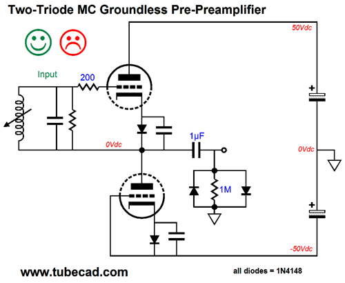
We can replace the 4.7k load resistor with another triode and cathode resistor, as shown below.
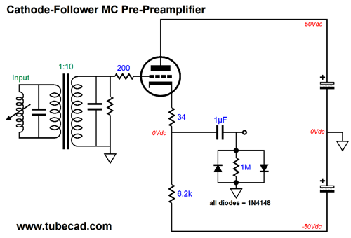
The unhappy face denotes the importance of ensuring that the cartridge coils are truly free floating and not grounded at the cartridge or tonearm. Returning to the idea of a singe-triode pre-preamplifier, we could use a step-up transformer and a cathode follower, as shown below.
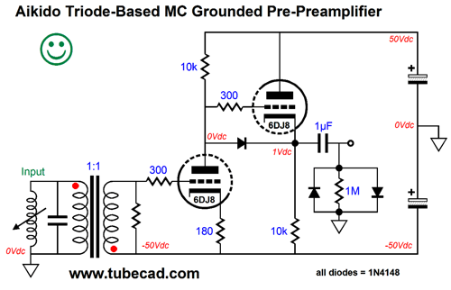
The step-up transformer's winding ratio of one to ten delivers all the voltage gain. The cathode follower provides a low-distortion and low output impedance output. The same PSRR enhancement obtains, as the output sits a power-supply null. The next step is to play with a different sort of transformer, one that does not step-up, but offers 1:1 coupling—an isolation transformer in other words. Isolation transformer are famous for their wide-bandwidth and low distortion. Some of which is due to a cheat of sorts, namely the capacitive coupling between primary and secondary works with the 1:1 coupling, not against it.
Note the flipped phase on the secondary; since the grounded-cathode amplifier inverts the phase, the result will preserve the cartridge's phase. (Of course, the phono preamp and line stage and power amplifiers may undo the phase along the way. Ultimately, you can set the phase at the speaker terminals.) We could had just as easily opted for the inverting-amplifier topology, but I wanted to use this topology instead. Why? Because I want to impose some constant-current-draw (CCDA) action on the circuit, as shown below.
The CCDA principle is that if the power supply sees a constant current flow, one unperturbed by the audio signal, then the power supply will have much less work to do and make of a contribution to the signal output. In addition, the protection diode between triodes will prevent the output from going through wild voltage swings at start-up, as the diode will be forward biased and lock the input triode's plate and the cathode follower's cathode to within +/-0.3V of ground level when the triodes are still cold but the rail voltages are fully developed. This is where I will stop, before I am tempted to write another thousand words on hybrid designs. Before signing off, I want to point out that the above circuit would also make a fine line stage amplifier. For that use, I would use a different tube, say a 6SN7 or 12AU7 or ECC99 or 5687, and higher power-supply rail voltages, say, +/-100Vdc, the same features would obtain, such as great PSRR and low output impedance. Of course, the two safety diodes at the output would no longer be used. But, John, aren't signal transformers just bad in general? No, not at all. They are not cheap, but they are useful in the extreme, particularly in breaking ground problems. I plan on doing a lot more experimentation with isolation transformers soon.
Next Time
User Guides for GlassWare Software
For those of you who still have old computers running Windows XP (32-bit) or any other Windows 32-bit OS, I have setup the download availability of my old old standards: Tube CAD, SE Amp CAD, and Audio Gadgets. The downloads are at the GlassWare-Yahoo store and the price is only $9.95 for each program. http://glass-ware.stores.yahoo.net/adsoffromgla.html So many have asked that I had to do it. WARNING: THESE THREE PROGRAMS WILL NOT RUN UNDER VISTA 64-Bit or WINDOWS 7 & 8 or any other 64-bit OS. I do plan on remaking all of these programs into 64-bit versions, but it will be a huge ordeal, as programming requires vast chunks of noise-free time, something very rare with children running about. Ideally, I would love to come out with versions that run on iPads and Android-OS tablets. //JRB |


| www.tubecad.com Copyright © 1999-2015 GlassWare All Rights Reserved |