| John Broskie's Guide to Tube Circuit Analysis & Design |
31 May 2015
Even More MC Pre-Preamps Where to start? I will retrace my steps and add what I left out last time due to space and time constraints, well mostly time restrictions. The easy way to solve the problem of getting just enough low-noise gain to boost the moving-coil (MC) cartridge's staggeringly runty output up to the puny output of a moving-magnet (MM) is the OpAmp.
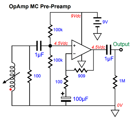
These ubiquitous, small, spider-like electronic devices are both relatively inexpensive and highly capable. Even a tube-loving man like myself will readily admit that the IC, and the IC OpAmp in particular, was one of the top-ten inventions of the 20th century and, perhaps, of all time. Often when I show one of my new topologies to an EE (electrical engineer) friend, his immediate response is: "Couldn't you just find an OpAmp that does that for you?" He isn't being lazy, as 99.9% of the time looking for a preexisting OpAmp or IC is the best solution for most electronic functions. For example, do you really want a tube-based garage-door opener, say one that sports 300B? Or a tube-based sonic toothbrush that hold pencil tubes? I thought not. So what sort of MC pre-preamplifier would most of my EE friends design ? Probably something like this:
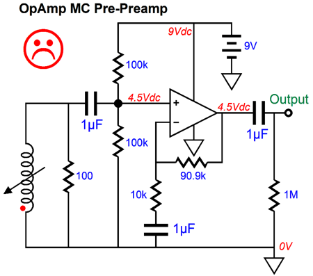
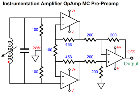
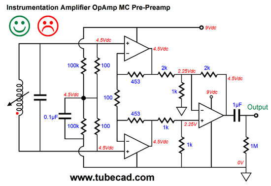
First, he—yes, he, as he is always a he; I do know one female EE, but she long ago moved up into management and has happily forgotten what she was taught about OpAmps—he would specify a low-noise OpAmp that would work with a 9V power-supply differential. If he is an old guy, which he most likely will be given my antique age, he will specify some relic from the 1980s, such as the NE5532 or LF357, claiming that they are more than good enough. If he is young, he will probably choose the AD797 or LME49710 or LT1028 or MAX44251. A knowledgeable audiophile, in contrast, might query the use of an electrolytic capacitor to terminate the 100-ohm feedback resistor, but if this circuit were enclosed within a fancy box that sported $20 RCA jacks and a $995 price tag, he would be proud to buy it at so low a cost. A solder-slinger, one who knows how to solder and is willing to solder and who frequents DIY audio forums, would probably alter the circuit to something like the following, bringing it inline with audiophile practice:
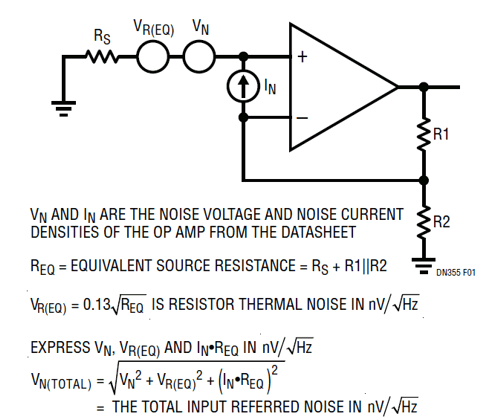
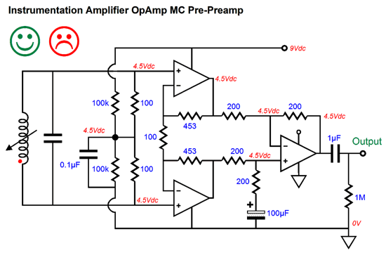
Banished is the cheesy electrolytic capacitor, having been replaced by a huge $50 copper-foil, audio-grade capacitor. So, why the unhappy face? This improvement just killed the OpAmp's greatest virtue, low-noise operation. How so, as nothing has really changed? The big change was the hundredfold increase in the feedback resistors' values. The 10k feedback resistor will generate ten times more noise than the OpAmp, which will flush its low-noise amplification down the drain. In contrast, the 100-ohm feedback resistor gives rise to about the same amount of noise as the OpAmp. Resistors making noise? John, what are you talking about? Resistors are passive devices that by themselves don't make anything? Sadly, no. The following is taken from an excellent explanation of how to obtain the lowest noise performance from an OpAmp, Op Amp Selection Guide for Optimum Noise Performance, Design Note 355 by Glen Brisebois of Linear Technology.
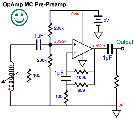
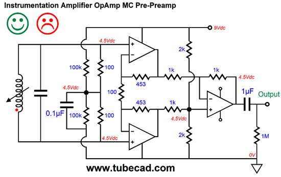
So are we doomed to live with the icky electrolytic capacitor? No. First of all why was it used in the first place? The answer is that it allows 100% of the DC portion of the output signal to be presented to the OpAmp's inverting input, which the OpAmp needs to center its output at 4.5V, and it sets the pre-preamplifier's low-frequency cutoff frequency, as this capacitor with resistor R2 (the 100-ohm resistor in the original schematic define a transition frequency. The formula is an easy one: F-3dB = 159155/C/R, where C is the capacitor's value in µF and R is the resistance. For example, with the 100µF capacitor and 100-ohm resistor, we get a low-frequency cutoff of 15.9Hz; with a 1k resistor, 1.59Hz. Thus, low resistor values must be matched with high capacitor values. Is there no way we can cheat the system and keep are low-frequency bandwidth and low-noise operation and still use the copper-foil capacitor? Indeed there is; just look below.
The 100-ohm and 909-ohm resistors are still there and the gain remains the same. The OpAmp needs to see 100% of its output DC voltage at its inverting input, which the 100k resistor still allows. The inverting input also needs to see a portion of the AC signal leaving its output, which the 1µF capacitor allows, as this capacitor is well-matched tot eh 100k resistor. In fact, the low-frequency cutoff has been lowered to 1.59Hz with this setup. If we desired to return the 15.9Hz cutoff frequency instead—due to excessive rumble perhaps—we would replace the 1µF capacitor with a 0.1µF one.
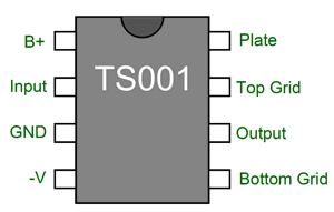
TS001 Tube IC One day, however, he did asked me if there was any circuit that tube-loving audiophiles could use in an IC package. I told him that the number of the tube-loving audiophiles in the entire world didn't exceed the number of people who were excessively fond of salty, black licorice; and that he was better off thinking about what blues, country, and rock musicians, all of whom were deeply tube-loving, might need, such as an auto bias IC or an LED-driver and voltage comparator circuit IC that would show the musician three LEDs, with the center being the correct idle current as he turns the bias potentiometer on his tube amplifier. Well, that encounter planted a seed in my mind about what I would do with only eight pins. Here is what I came up with: the TS001, with "TS" standing for Tube Sound.
Impressive isn't it? This little plastic jellybean with eight legs and a pair of beefy output triodes, say a 5687 or 6H30 or ECC99, and a high-voltage power supply makes a good start towards building a fine OTL headphone amplifier. In other words, the TS001 would be used to set up a unity-gain OTL output stage, automatically adjusting the idle current and centering the output at half the B+ voltage and providing the top and bottom output tubes with their required signal amplitudes. Moreover, the TS001 would apply a good amount of negative feedback to keep the triode's output in line with the TS001's input signal.
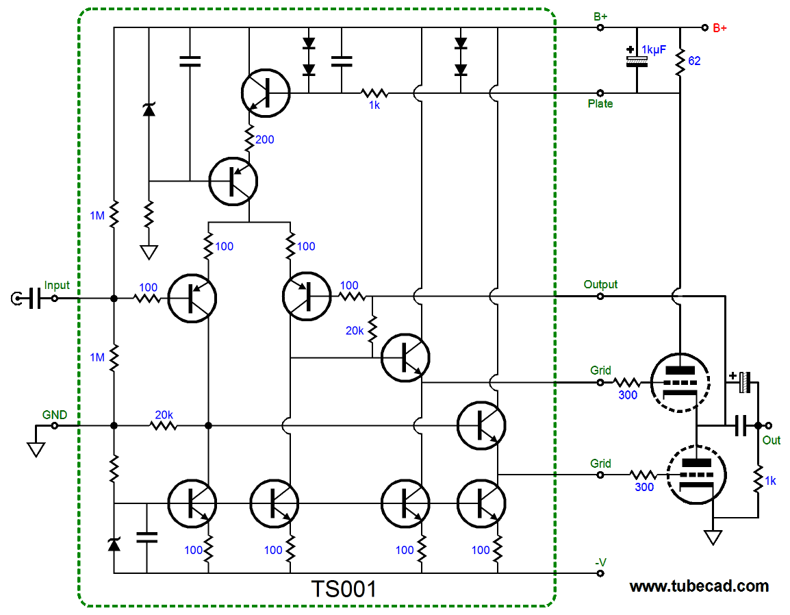
The assumption is that class-AB would be used; thus, the two-diodes-in-series signal clipper at the top, between the B+ and Plate pins. The two diodes limit the voltage drop across the 62-ohm current-sense resistor. They also perform like a saturating choke, limiting the voltage drop across the plate resistor to no more than about 1.4V, so the output stage does not lose too much B+ voltage, which would be important when driving 16-ohm headphones. At idle, the voltage drop across the current-sense resistor would equal a little over 0.6V. So, with a 62-ohm current-sense resistor, the idle current would be 10mA; with a 6.2-ohm current-sense resistor, 100mA. What happens when the output stage leaves it class-A window of operation and moves into class-B, with much greater current swings, say over 100mA? The two diodes clip the voltage drop across the current-sense resistor, making a waveform that closely resembles a squarewave present to the TS001's plate pin. The average value of this waveform will be close to 0.62V, so the existing idle current setting remains in place. I doubt that the such high-voltage transistors could be housed within a DIP 8-pin IC (but, perhaps, they could be used in a 7-pin TO-220 package, with the tab serving as the ground connection). Nonetheless, I love the look of the thing. If one positive power-supply rail, say +100V, and two negative power-supply rails were used, say -100V and -140V, with the TS001 attaching to the more negative one and its GND pin attached to the -100V PS rail, then the OTL OPS could be built with a bipolar power supply and no output coupling cap would be needed. Indeed, a OTL for driving speakers could be made, given robust enough output tubes and power-supply rails. In my notes, I found this second variation:
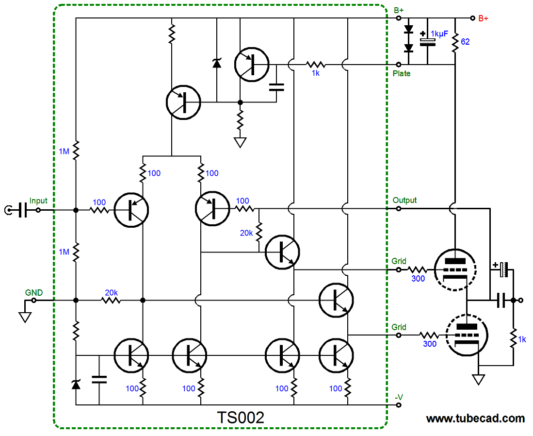
The two diodes have been placed external to the IC. Why? My guess is that I wanted to use big, ultrafast rectifiers, like the MUR410G, and comparable diodes would not fit within the IC package. The bastode stage was swapped for a generic constant-current source. In both circuits, the current flowing through either the bastode transistor pair or the single-transistor constant-current source will set the grid-bias voltages for the output tubes.
Back to MC Pre-Preamps: Hybrid Design
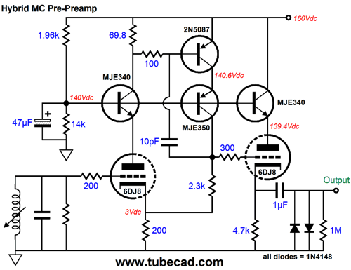
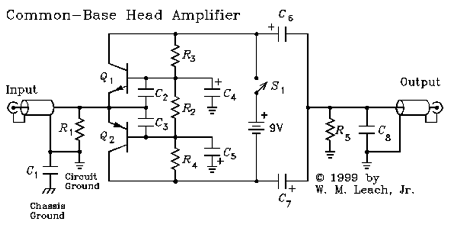
This circuit also exhibits a fine PSRR, as the two MJE340 NPNP transistors shield the two 6DJ8 triodes from the power-supply ripple. The 2N5087 PNP transistor monitors the voltage drop across the 69.8-ohm resistor. If the voltage varies, the PNP 2N5087 alters its current conduction to undo the varying voltage drop, striving to maintain a constant voltage drop. The result is that a fixed gain of 10 (+20dB) is established at the output. Thanks to reader, Bill Waslo, I was reminded of W. Marshall Leach, Jr.'s altogether ingenious two-transistor MC pre-preamplifier.
Like the Circlotron, the power supply, in this case the 9V battery, is not grounded, but floats. (By the way, I have seen an inverted version of this circuit, where the emitters are separated and coupled to the input through coupling capacitors, so the two collectors tie together and terminate in the load resistance; the design was an RF signal isolator amplifier.) Well, in Mr. Leach's description of the circuit's functioning, he mentions that he replaced the 2N5087 with a 2N4403 PNP transistor and got much lower noise as a result. I would do the same with my design.
DIfferential MC Pre-Preamps: Hybrid Design
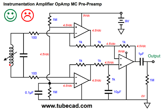
By using quiet OpAMps and a bipolar power supply, the above circuit would yield excellent results, as it offers, low-noise, high CMRR, low DC offset, and low distortion. Okay, are we done? Can we quit now? No. What if we want to use battery power? Well, two 9V batteries are twice the hassle of one 9V battery, so why not use a single 9V battery? We can, but we will need some extra capacitors:
Like a small zit on an otherwise lovely face, our eyes are drawn to the icky electrolytic capacitor. Once again, if this circuit, including the icky electrolytic capacitor, were housed in a fancy box, most would be happy to pay $995 for it. Well, how do we lose the electrolytic capacitor? Maybe we shouldn't. Not all electrolytic capacitors are equally icky, as some the best types sound quite good. Moreover, non-polarized electrolytic capacitors sound far better than their polarized brothers. Another idea is to no use no capacitor at all.
Note how the output voltage remains centered at half the B+ voltage. Note how the two 2k resistors present a parallel resistance of 1k, so the same 50% signal division obtains as if a single 1k resistor that went to ground was used. Well, this circuit would work fabulously in SPICE simulations, but maybe not so well in reality. Why the difference? In SPICE, the B+ would be perfect, presenting neither noise nor any impedance. Reality differs. Another approach would be the following:
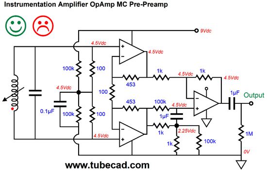
The workaround here is to forgo the electrolytic capacitor and throw away some of our negative feedback. This variation could work well in both SPICE and reality. The potential problem is that the last OpAmp may not be happy with the inputs signals being only 2.25V more positive than its negative-power-supply pin. For example, the AD797 data sheet states than the minimum power-supply differential voltage to be 10V; and I wonder how well its NPN-based differential input stage would be with the 2.25Vdc input signal. On the other hand, the input signal swing is microscopic and we only need to swing a few millivolts at the output. Still, this is a concern. Another possibility is to use a trick similar to what we used before with the single OpAmp.
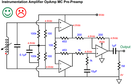
The 100k resistor provides the needed DC signal, while the 1µF film capacitor provides the AC signal. Because the two 100k resistors are effectively (in AC terms) in parallel with the two 1k resistors, we do not need to worry about higher noise due to higher resistor values. By the way, I snuck in 1k resistors in place of 200-ohm resistors without making any comment on this move. The idea is that since we are using a single 9V battery, we must strive for long battery life, which results from drawing less current. Well, 1k resistors draw 1/5th as much current as 200-ohm resistors. Since we must live with 1k resistors, perhaps, we can get away with the following.
We can use a 10µF film capacitor, which need not be all that large, particularly with a lower voltage rating, as there is no need to use 1kV capacitors—other than better sonics, perhaps. Before leaving the topic of instrumentation amplifiers, I should point out that you can build an inverting version.
This configuration is seldom used, as common-mode signals will get amplified by the two input OpAmps, which will be eliminated by the last opAmp stage, but which may overload the input OpAmps, not that this is likely in an MC pre-preamplifier.
Super-Simple Differential MC Pre-Preamplifier
This MC pre-preamplifier draws 8.3mA of current per channel. Most alkaline 9V batteries are worth at least 500mA-hrs. In other words, you can draw 1mA for 500 hours or draw 50mA for 10 hours. Well, with a draw of 8.3mA, we would get 60 hours of playing time, assuming one 9V battery per channel. So, if you do three hours of LP listening a day, that's two months of battery life. On the other hand, Ni-CD offer much lower ESR (effective series resistance) than alkaline 9V batteries do, so they may prove a much better choice. Ni–CD 9V batteries usually only have six cells within them, so only deliver a voltage of 7.2 volts, you can buy, however, a Ni-CD 8.4V "9V" battery. Unfortunately, these rechargeable batteries are only worth about 120mA hours before requiring a recharge. On the other hand, a cheap 12V gel-cell, sealed, lead-acid battery can put out 2,000mA-hours.
Speaking of batteries, last year, after my post on battery-bias for tubes, Jeremy Epstein wrote me an excellent e-mail, which he has given me permission to post here:
Thanks Jeremy.
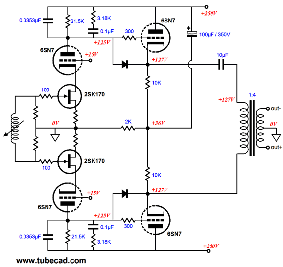
Differential Tube-FET MC Pre-Preamp
The 2SK170 FETs are cascoded by the 6SN7 triodes, which ensures high gain and wide bandwidth. The cascoding, however, delivers amazingly poor PSRR, next to nothing, in fact. In this circuit, this not problem, as the output transformer naturally rejects common-mode signals, passing only differential signals; thus, the power-supply noise falls out of the equation, leaving only the desired output signal. Note how the RIAA equalization is passively applied at the plate resistors. Also note how these two equalization networks terminate into the B+ connection, not ground. This explains the addition of the 2k shared cathode resistor and 100µF capacitor at the cathode follower stage, as we want the cathode followers to be referenced to the B+ not the ground. The schematic shows a balanced output, but it could just as easily offer an unbalanced output. Housed in fancy box and sporting a $3,995 price tag, most audiophiles would be delighted to buy it. I am in the wrong business! If only I had less shame.
Differential Transistor MC Pre-Preamp
DC coupled, balanced in and out, this pre-preamplifier is meant to feed two triodes, whose cathodes are grounded and whose grids would welcome the -1.95Vdc bias voltage presented at the balanced outputs. As many will have a hard time seeing how the topology works, let turn on its head by using NPN transistors instead.
Ah, that's much better. Two common-emitter amplifiers feeding two emitter followers. Two NFB loops that establish the gain and the DC relationships. Simple. Note how the two output coupling capacitors are needed now. Also note the 0.7Vdc DC offset at the inputs. As long as these two match each other, the cartridge is safe. If we wanted to be extra safe, we could place two safety diodes in parallel, in opposite directions, across the cartridge coil. This pre-preamplifier offers a gain of 10 (+20dB), but is more gain is needed, we can use this variation.
A gain of about 40 (+32dB) is realized here. The emitter followers draw a great deal of current, so higher-value resistors might be needed in place of the 40-ohm resistors. If the inclusion of the icky electrolytic capacitors is bothering you, I wouldn't worry too much, as the two feedback loops encompasses them. Why are they there in the first place? They help create a poor man's constant-current source, by making the bottom 300-ohm collector resistors effectively much greater in value. Once again, what I thought would be a quick, short post turned into something much bigger.
Next Time
User Guides for GlassWare Software
For those of you who still have old computers running Windows XP (32-bit) or any other Windows 32-bit OS, I have setup the download availability of my old old standards: Tube CAD, SE Amp CAD, and Audio Gadgets. The downloads are at the GlassWare-Yahoo store and the price is only $9.95 for each program. http://glass-ware.stores.yahoo.net/adsoffromgla.html So many have asked that I had to do it. WARNING: THESE THREE PROGRAMS WILL NOT RUN UNDER VISTA 64-Bit or WINDOWS 7 & 8 or any other 64-bit OS. I do plan on remaking all of these programs into 64-bit versions, but it will be a huge ordeal, as programming requires vast chunks of noise-free time, something very rare with children running about. Ideally, I would love to come out with versions that run on iPads and Android-OS tablets. //JRB |
Kit User Guide PDFs
E-mail from GlassWare Customers
High-quality, double-sided, extra thick, 2-oz traces, plated-through holes, dual sets of resistor pads and pads for two coupling capacitors. Stereo and mono, octal and 9-pin printed circuit boards available.  Aikido PCBs for as little as $24 http://glass-ware.stores.yahoo.net/ Support the Tube CAD Journal & get an extremely powerful push-pull tube-amplifier simulator for TCJ Push-Pull Calculator
TCJ PPC Version 2 Improvements Rebuilt simulation engine *User definable
Download or CD ROM For more information, please visit our Web site : To purchase, please visit our Yahoo Store: |
|||


| www.tubecad.com Copyright © 1999-2015 GlassWare All Rights Reserved |