| John Broskie's Guide to Tube Circuit Analysis & Design |
07 June 2015
Autoformers in General
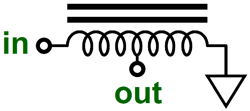
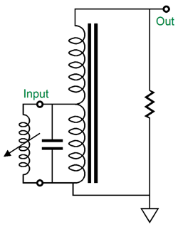
Like a transformer, an autoformer can decrease or increase AC voltages and AC currents, along with impedances. Like a transformer, an autoformer can never increase power, although like a transformer, alas, it can lose some power, due the wire's resistance and core losses. Like a transformer, an autoformer is usually made from solid-core, enameled copper wire and a laminated steel core. Like a transformer, an autoformer can either hold or not hold an air-gap in the core's structure, so some autoformers can sustain a DC current flow, while other are strictly AC devices. Unlike a transformer, an autoformer provides no isolation; hence, its relative rarity. The reason we audiophiles should care about the autoformer is that it can easily outperform its more famous brother, the transformer. Autoformers are smaller, lighter and offer wider bandwidth and less phase shift and insertion losses than a comparable transformer. Making sense of how the autoformer works is not really any harder than making sense of how a transformer works. Let's begin with a super simple autoformer whose center tap is at exactly 50% of the single winding—think of it as a center-tapped choke.
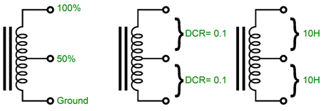
The inductance and DC resistance measured from the ground tap to the center tap equals the inductance and DC resistance measured from the input tap to the center tap. As a result of this 50% division of turns of wire about the core, the output AC voltage measured from the center tap to the ground tap will be 50% of what is presented to the input tap and ground.
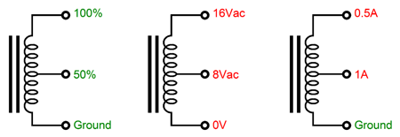
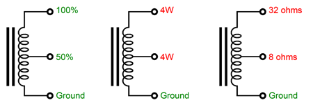
In the example above, we see that 16Vac is applied across the entire winding and 8Vac appears from the center tap to the ground tap. Because we can only alter the form energy takes, never destroying it, the current flow available at the center tap will be twice that which is applied across the entire winding. In other words, with the exception of some core and copper losses, which will turn a small portion of the input power into heat, the autoformer is a constant-power device. In this example, 4W goes in at the top and 4W comes out at the center tap.
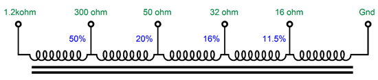
The impedance ratio is equal to (1/tap-ratio)²; thus, in this example, 1/0.5 equals 2, which squared equals 4, so the impedance ratio is 4:1. In other words, an 8-ohm loudspeaker placed across the center-tap and the ground tap will be reflected as a 32-ohm load to the entire winding. This is a godsend for those running OTL and Circlotron amplifiers, as 8-ohms is a brutally low load impedance for any tube to work directly into. Of course, we do not have to place a tap at 50%, as we can pick any ratio we need. For example, I have been tempted to have the following autoformer custom made for tube-headphone-amplifier use.
As far as the tube-based headphone amplifier is concerned, the load is 1200 ohms, even if the actual headphone impedance is only 16 ohms. Needless to say (so why am I saying it?) 1,200 ohms is a much more gentle load than 16 ohms. As far as the coupling capacitor is concerned, the load is 1,200 ohms, so its value need only be about 10µF, not the 500µF that the 16-ohm headphones would seem to imply. Do not forget the strict laws of physics: you never get anything for free. In this case, the headphone amplifier must deliver a output voltage swing of 8.66Vpk and 7.2mA peak to get 1Vpk and 62.5mA peak into the 16-ohm headphones. Note how 8.66Vpk against 7.2mA equals 58mW (avg) and 1Vpk against 62.5mA equals the same peak wattage, save for some small rounding errors along the way. No free lunches here, just a better matching of impedances and, thus, a greater realization of power transfer.
Autoformers and Speakers
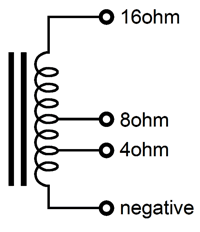
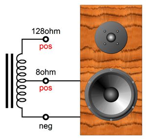
With the above autoformer, the solid-state class-A power amplifier designed to deliver 30W into 8-ohms can now deliver 30W into both 16-ohm and 4-ohm speakers with no problems. A slightly less obvious use for an autoformer is to make an 8-ohm speaker more compatible with an OTL amplifier. Believe me, if all speakers held such an autoformer, 300B OTL power amplifiers would be common.
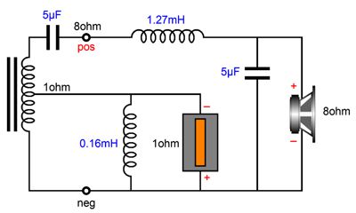
(Here is a quick quiz: what is the winding ratio needed to make the 8-ohm speaker appear as a 128-ohm load to the OTL?) Now, fasten your mental seatbelts. Ribbon tweeters can deliver amazing high-frequency response, which is why they often appear in super expensive speaker systems. The big problem for the maker of these tweeters is getting the impedance up to 8 ohms, as very little metal foil is needed in their construction and even the thinnest short strip of metal foil offers little resistance, far less than 8 ohms worth. Remember from my explanations on the topic of current output amplifiers, the force that compels a speaker's diaphragm's movement is due to flow of current within a magnetic field. F = B·l·i Where B is the magnetic flux density; l the wire length in the magnetic field; and i is the current flow. Notice that Voltage and Resistance do not appear in the formula. The more current flowing, the more movement. Ideally, a speaker would present a DCR and an impedance of only a few milliohms, as resistance only adds heat to the mix. (Now, if there were a thermal speaker, whose movement was the direct result of heat being generated, say some expanding and contracting gases, then resistance would not be a waste, but an essential and productive part of the creation of sound. For normal speakers, heat is just wasted energy.) Thus, the makers of ribbon tweeters are in a bind, as they dare not go much below 4-ohms in impedance and yet they could make a much better tweeter but it might present only 1-ohm (or much lower) of resistance. The solution would be an autoformer, with a tap at 35% of the winding.
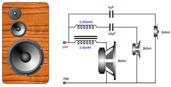
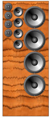
In the above illustration, we see a conventional 8-ohm woofer wed to a 1-ohm ribbon tweeter. As far as the amplifier is concerned, the load is 8 ohms. As far as the 5µF capacitor is concerned, the tweeter is an 8-ohm type; but as far as the 0.16mH inductor is concerned, the tweeter presents only 1-ohm of resistance. This saves us money both ways, as a 1-ohm tweeter would require a 40µF capacitor to crossover at the same frequency; and an 8-ohm tweeter would require a 0.8mH inductor. In other words, not only do we get the benefit of a high-current ribbon tweeter, we save on crossover parts. Note the phase reversal on the tweeter, which is due to the 2nd-order crossover imposing a 90-degree phase shift at the crossover frequency on both the woofer and tweeter, which would otherwise result in the tweeter being out of phase with the woofer, thereby creating a deep null at the crossover frequency. Okay, after that mental warm-up, let's have a brief cool-down period. The following is a generic speaker, nothing fancy, just a big woofer and small midrange and dome tweeter—a speaker your grandfather would recognize and might have bought or, even, built.
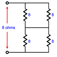
First-order filters are used throughout and the crossover frequencies are at 500Hz and 5kHz. Now what would happen if we stacked four of these speakers, one atop the other? Well, we could end up with a 32-ohm load, if all the speakers were wired up in series; or, a 2-ohm load, if wired in parallel; or an 8-ohm load, if we used the series/parallel configuration.
The impedance remains unaltered, in this series/parallel configuration, but what happens to the efficiency, with four speakers blaring at once? Well each speaker only sees 50% of the voltage the amplifier puts out, so we incur a -6dB loss; but as we have quadrupled the radiating surface, we gain a +12dB boost in SPL, so we end up with net gain of +6dB. For example, four 90dB speakers placed in this series/parallel configuration will effectively present an SPL of 96dB with 1W at one meter. Nice for those with wimpy tube amplifiers. By the way, do not imagine that this is too silly of an idea. One of the best sounding systems I have ever heard was when four small, high-quality, mini monitors were stacked up four high, with one facing forwards, one facing backwards, and two facing the adjoining wall. Amazing stereo image. That's great, John, but what happens if you have kids or a dog or a spouse that sleepwalks and you don't want your tower of speaker to fall over? I see your point, but a speaker stand could be devised that securely held all four speakers together. The easy solution, however, would be to build a bigger speaker enclosure that could house all 12 drivers.
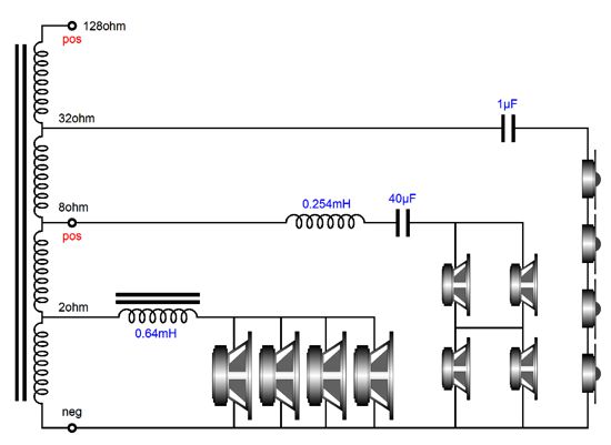
If nothing else, such a design would save 75% on the crossover parts, as four identical crossovers would not be needed. Now it is time to return to the topic of autoformers. Given the above speaker, how could we exploit an autoformer? One possibility is the following.
The amplifier attaches to the 8-ohm tap and ground—that is if the amplifier is a conventional solid-state or transformer-coupled tube amplifier, as the load presented to the amplifier is 8 ohms. If an OTL amplifier is used, then we would use the 128-ohm tap and ground tap. That was the simple part. Now the harder part. Beginning with the woofers, four 8-ohm woofers in parallel will equal a 2-ohm load, a brutally-low load impedance even for solid-state amplifiers. But the amplifier sees an 8-ohm load due to the autoformer. The woofers all see the same voltage, but only one half of what the power amplifier put out, thus we incur a -6dB loss; but we have four times the radiating surface area of one woofer, so we gain +12dB in SPL, thus making a final total of +6dB. Why did we take this giant step sideways? The inductor is lower in value by four over the inductor that worked with an 8-ohm load. Smaller is cheaper and better, as lower inductance means lower DCR; of course, this reduction in DCR is somewhat mitigated by the 2-ohm load impedance. Moving on to the midranges, we started with 8-ohm drivers and we ended up with an 8-ohm load. so the exact same crossover parts are used. But, due to the series/parallel arrangement, we gain +6dB of SPL per watt. In addition, the four midranges can handle four times the power that a single midrange could. Ending with the tweeters, we see a 32-ohm load imposed by the four tweeters in series. Since each driver sees one fourth of the signal voltage, we suffer a -12dB loss, but we gain +12dB due to the fourfold increase in emitting surface, so a wash obtains, as -12dB + 12dB equals 0dB. Note, however, that the autoformer delivers twice the signal voltage, so we gain +6dB in SPL, bringing the tweeters inline with woofers and midranges. Most importantly,we got away with a 1µF crossover capacitor, rather than the 4µF capacitor an 8-ohm load demands. Is this a big deal? It can be if you are buying $50 capacitors. I am not sure that a copper-foil 1µF crossover capacitor cost only one fourth as much as 4µF copper-foil capacitor, but I am sure it cost a lot less. In sum, by using an autoformer we not only made the speaker OTL friendly, we saved some money on the crossover.
Autoformers as MC Step-Up Devices
Let's say that we need a step up of 10 (+20dB). The autoformer would need to be tapped at 10%. I would definitely keep whatever shunting capacitance is required on the cartridge's side. What about the load resistor, which might be 100 ohms? I would definitely load the top of the autoformer, rather than across the cartridge. Why? All inductive devices desire low-resistance termination, ideally zero ohms, a dead short; just as all capacitors prefer high-resistance termination, ideally infinity. Well, do we use a 100-ohm resistor? No. Instead, we must work out the impedance ratio of the autoformer. In this example, the impedance ratio is 1:100, as the step ratio was 1:10 and 10² is 100. Thus, the resistor's value must equal 100 against 100, or 10k.
Why Do Autoformers Cost So Much?
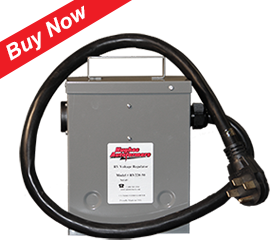
This baby boasts the following features:
What would an audiophile expect to pay for 50A and 12,000W delivery and 35lbs? A good guess would be $1,000 per pound. Well, as this autoformer is meant to be used by those who own RVs, as in recreational vehicles, the price is only $548, not $35,000. Remember my faux advertisement for Sonic Gold cables? Some never get my jokes, which prompts me to wonder how many wanted to buy Sonic Gold cables from Artifice Audio, a bargain at only $12,349 for 20-foot lengths.
The high audio prices are due to two factors, rarity and troubling psychological issues. If only a handful of iPad-like tablets were sold each year, then they would cost $10,000 each. There is amazing efficiencies to be gained by mass production. For example, if Honda made millions of large, tall, full-range ribbon speakers, they would cost $1,000 each, not $40,000. Electronic parts that cost over a dollar each had be had for 25 cents, if you buy 1,000 of them. Do not forget that handmade is expensively made. When you seek out hand-wound autoformers, you must expect to pay far more than what a machine-made autoformer would cost—lots more. While this explains much of the high cost, it cannot explain all of it. For example, audio autoformers made for sound-distribution systems are reasonably priced. If these autoformers were sold to audiophiles, however, they would have to be housed in zebra-wood boxes, wreathed in Teflon, and and soaked in gold, as they would cost ten to twenty times more. The question—Who would pay so much more for a fancy box?—does not need to be answered, as we all know the answer: we would. For almost all audiophiles, the media is the message, the wrapper is the candy bar, the fancy enclosure is the sonics.
In the year before his death, the late Dr. Gizmo (Harvey Rosenberg) and I became friends. Long ago, before I sold PCBs and kits, when my only audio endeavors were writing the Tube CAD Journal and creating tube-related software, he contacted me to tell me that I had won the Triode Guild's "Platinum Brain" award. (I wanted to get a personalized license plate that read: "Pt Brain," but it could not pass the wife acceptance factor.) Here is what I wrote at the time:
I ended with a quote:
I never met Gizmo in person, but we did swap many long phone conversations. He was a triode evangelist, an audio-ecstasy crusader. His sincere desire, hope, and longing was for the joys of tube-based audio to be extend beyond the small clusters of old, well-off men with more money than common sense. His goal was that one should be able to buy a fantastically great-sounding audio system for about $2,000; that was $2,000 for everything, speakers and amplifiers and CD player or turntable, not just one interconnect or power cord.
What he thought the world really needed was new Stereo-70, but with a larger chassis, a chassis far wider and deeper than it need be, an almost silly spaciousness, so it would not only allow modification, but it would positively invite it. As he saw it, American teenagers needed something to hotrod, something to modify that would personify and exemplify the modder's character, temperament, emotions, and personality. And since cars were now too expensive and too complicated and too regulated (is it even legal to create a hotrod today?) for ready modification, something else would have to take their place. As he saw it, tube-based audio gear could fill that void, as it was simple and yet yielded deeply satisfying results. Thus, our long phone calls, while we discussed how a universal Stereo-70 could be designed and built. During one such call, he told me what I already knew. He had originally manufactured toys and he had decided to create a tube-audio company named "Tube God." His plan was simple: he would hire the best electronic designers and use the best parts to build the best audio equipment, which would then be housed in ugly boxes, as he wanted to sell sonic performance, not jewelry boxes. His effort failed. A few years later, he came out with the same products in fancier boxes and he was successful. Audiophiles will not buy ugly boxes. See at the bottom the excerpt I took from Harvey Rosenberg's little booklet, Tube God, to get a good idea of the battle he was fighting against, amongst other things, the notion that "People listen with their eyes."* About 25 years ago, a famous audio personality took me aside and told me that he didn't make any money in this business until he discovered the secret to success in audio: at least 50% of the cost of a piece of equipment must go into its cosmetics. I cannot resist the urge to quote myself. From blog number 278:
A few More MC Pre-Preamp Circuits
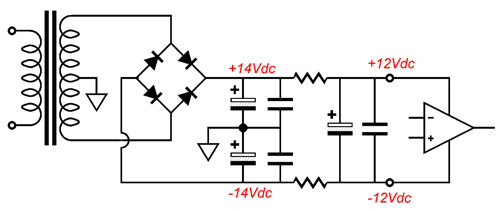
Why does the name include the word "Aikido?" This circuit sidesteps power-supply noise, rather than employ brute-force means to quell the noise. At each transistor's collector there is plenty of noise, but as long as the power-supply rails present equal but out-of-phase ripple, the noise nulls at the junction of the two 1µF coupling capacitors. Even a simple, non-regulated, RC-filtered bipolar power supply will work surprisingly well.
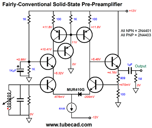
Another circuit that I found hiding was the following, a somewhat conventional design—well, conventional at least for me.
The only snazzy portions are the inclusion of the extra PNP transistor at the current mirror at the circuit's top and the addition of the rectifier in between the NPN differential pair. The latter device was added as voltage-offsetting device that would allow the DC feedback loop to force the left differential transistor's collector to +5.46Vdc. (Bypassing the MUR410G with a 1kµF capacitor will lower the distortion a tad.) By the way, we can forgo the use of the emitter follower, with the addition of a pull-up resistor, but the distortion will rise, albeit in a single-ended fashion, with more 2nd harmonic content.
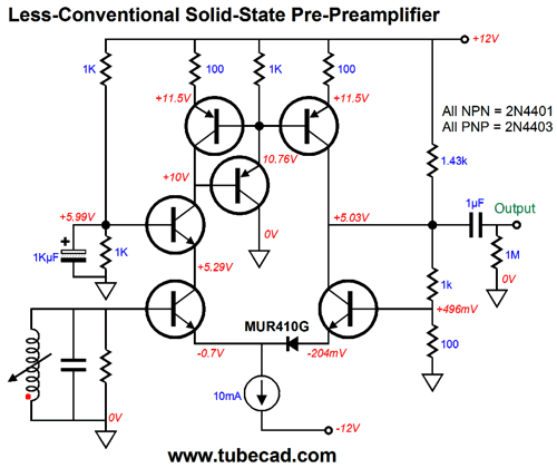
The constant-current source's idle current was pumped up to 10mA. Why? The naked differential amplifier must now drive the negative-feedback resistors. Let's now move on to more interesting circuits.
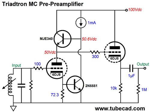
The above circuit is a Triadtron variation. The 2N5551 transistor at the cathode resistor acts to prevent any alteration in current flow through the input triode. The only way that a triode can maintain a fixed current flow in the face of a change in grid voltage is for there to be a countering change in either its cathode voltage or plate voltage. Well, since the transistor strives to prevent a change in cathode voltage, the plate voltage must change. By how much? That is easy: by the mu (the amplification factor) of the triode. For example, if a triode sees a 1V increase in grid voltage and its cathode voltage is fixed, then its plate voltage must fall by mu volts to maintain the same current flow. But what if we do not need a gain of 33, which is what the 6DJ8 would deliver? We could use a lower-mu triode, such as the 6H30, 12AU7, or ECC99.
Next Time
*An Excerpt from Harvey Rosenberg's Tube Bible
WHY YOU ARE AN AUDIO CYNIC
We know that many audiophiles are unhappy and angry. They are unhappy because high quality electronics are expensive, and they are angry because there is a general lack of integrity on the part of manufacturers. These attitudes are totally justifiable because of the following set of circumstances: There seems to be an unspoken and unwritten set of rules in the audio industry that most companies subscribe to as the formula for success.
User Guides for GlassWare Software
For those of you who still have old computers running Windows XP (32-bit) or any other Windows 32-bit OS, I have setup the download availability of my old old standards: Tube CAD, SE Amp CAD, and Audio Gadgets. The downloads are at the GlassWare-Yahoo store and the price is only $9.95 for each program. http://glass-ware.stores.yahoo.net/adsoffromgla.html So many have asked that I had to do it. WARNING: THESE THREE PROGRAMS WILL NOT RUN UNDER VISTA 64-Bit or WINDOWS 7 & 8 or any other 64-bit OS. I do plan on remaking all of these programs into 64-bit versions, but it will be a huge ordeal, as programming requires vast chunks of noise-free time, something very rare with children running about. Ideally, I would love to come out with versions that run on iPads and Android-OS tablets. //JRB |
Kit User Guide PDFs
E-mail from GlassWare Customers
High-quality, double-sided, extra thick, 2-oz traces, plated-through holes, dual sets of resistor pads and pads for two coupling capacitors. Stereo and mono, octal and 9-pin printed circuit boards available.  Aikido PCBs for as little as $24 http://glass-ware.stores.yahoo.net/ Support the Tube CAD Journal & get an extremely powerful push-pull tube-amplifier simulator for TCJ Push-Pull Calculator
TCJ PPC Version 2 Improvements Rebuilt simulation engine *User definable
Download or CD ROM For more information, please visit our Web site : To purchase, please visit our Yahoo Store: |
|||


| www.tubecad.com Copyright © 1999-2015 GlassWare All Rights Reserved |