| John Broskie's Guide to Tube Circuit Analysis & Design |
13 June 2015
More Super-Triode Amplifiers
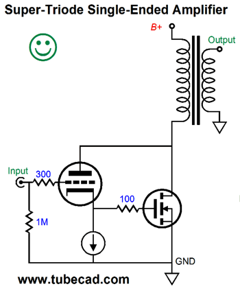
The triode does not deliver any power into the loudspeaker, as it conducts a steady current. But it does govern the flow of current through the MOSFET in a predictable and controlled fashion. This results from the triode's amplification factor and plate resistance, which means that the triode cannot be replaced by a another MOSFET or pentode. The only way the triode can maintain the same idle current in the face of a positive grid voltage is for the triode's plate voltage to drop by mu times as much as its grid went up in voltage. For example, a 6SN7 presents a mu of 20, so a +1V increase in grid voltage could be countered by a -20V drop in plate voltage. Conversely, a -1V decrease in grid voltage could be cancelled by a +20V rise in plate voltage.
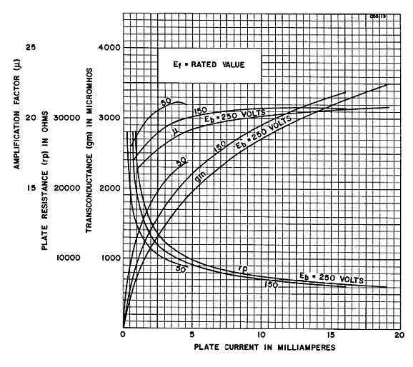
Note how the above graph shows that the 6SN7's mu is not a fixed 20, but curves from 17 to about 21. Well, the triode's curvature will be mapped onto the amplifier's output. That was the super-triode's operation in a nutshell. Okay, what if we do not want a single-ended hybrid power amplifier, preferring a push-pull amplifier with no output transformer? Well, we can make a push-pull super triode amplifier out of an existing solid-state power amplifier, as shown below.
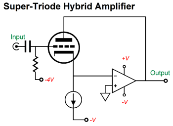
Of course, you cannot just terminate the triode's plate into the solid-state power amplifier's output. (Well, actually you could, if the solid-state power amplifier's output presented a 100V DC offset.) Thus, we need to add a big capacitor to bridge the triode's plate and the solid-state power amplifier's output, at least in AC terms.
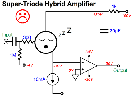
Great, John; can we quit now? No. What happens at start-up, when the triode is cold and not conducting, when it is yet to be awaken? Nothing good.
The constant-current source (CCS) pulls the solid-state power amplifier's inverting input all the way negative, so the solid-state power amplifier's output swings up and latches to the positive rail voltage and your woofers do a push-up against the facing wall. Not good. The workaround is to add a coupling capacitor to the circuit.
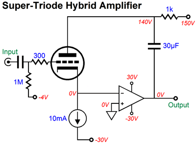
Note how the CCS no longer terminates into the negative power-supply rail, but ground. As long as the triode offers a low to medium mu, this will work well. If, on the other hand, the triode is a high-mu type, then the CCS is likely get insufficient voltage to operate, so the connection to the negative power-supply rail will have to be restored. The quick formula for figuring out the required grid voltage for a certain idle current and with a certain plate voltage and a ground cathode is: Vg = (rp•Ip - Vp) / mu The formula for finding the required cathode voltage for a certain idle current and with a certain plate voltage and a ground grid is: Vk = (Vp - rp•Ip) / (mu +1) Okay, let's flesh-out the design by adding the missing part values.
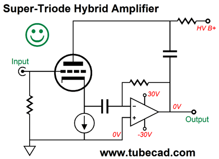
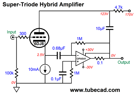
Note the use of the OPA541, not an LM3886. Why? The OPA541 is a far more stable design that can even sustain unity-gain operation, which the LM3886 cannot. Also note the matching 1M resistors. The top 1M resistor allows the OPA541 to receive the DC feedback from the output, so the amplifier can eliminate a DC offset at its output. The bottom 1M resistor helps keep the DC offset extra low, as it presents the same resistance to the non-inverting input as the inverting input sees. The 0.1µF helps shunt away much of the noise the high-valued resistor produces. This amplifier's gain will equal the 6DJ8's mu of 33. Moreover, the 6DJ8 will leave its imprint on the solid-state power amplifier's output, which is what super-triode amplifiers are all about. The output impedance proves amazingly low.
Returning to Super-Triode Single-Ended Amplifiers
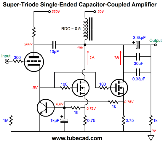
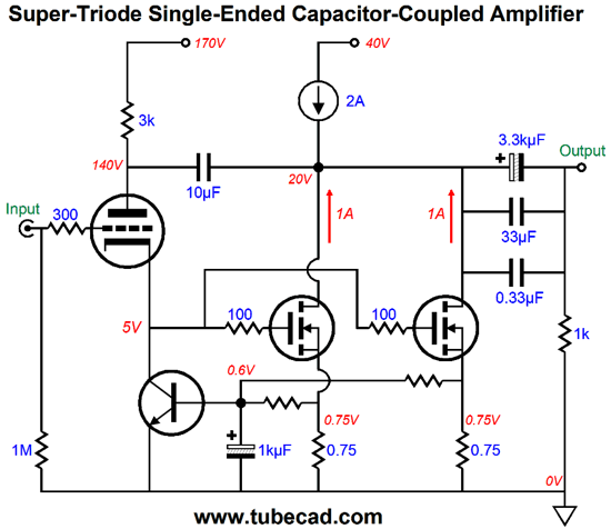
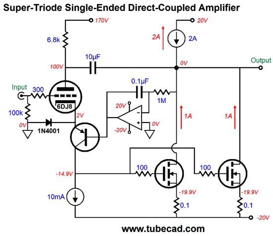
Two N-channel power MOSFETs are used, say two IRFP240 types, which cost less than $2 each in quantities of ten, so that we can get more transconductance and lower the heat each must dissipate by half. The NPN transistor sets the idle current through the MOSFETs by monitoring the voltage drop across the source resistors. This transistor also functions as a constant-current source (CCS) to load the triode's cathode. The 10µF capacitor effectively connects the triode's plate to the output, at least in AC terms. The many coupling capacitors in parallel are there to protect the speaker from the 19Vdc at the drains. The big electrolytic capacitor is bypassed by a big film capacitor, which in turn is bypassed by a small film capacitor. Finding an audio-grade choke is tough, as most were designed to work best at 120Hz ; in addition, it will prove big, heavy, and expensive. We could replace it with an active CCS, which entails bumping the rail voltage up from 20Vdc to 40Vdc. And the high-current CCS will need a large heatsink. This will also lower to the amplifier's efficiency to no more than 25%, the theoretical maximum. In fact, the actual amplifier efficiency will be only 20%, which is still pretty good for a single-ended power amplifier. How do we know that value? At idle, the entire solid-state output stage will dissipate 80W, 40V against 2A, and we know that the maximum symmetrical power the 2A idle current allows is 16W, as (2² x 8)/2 equals 16W; and 16W divided by 80W equals 20%. In other words, because bigger heatsinks will be needed, and because a twice as powerful power supply will be needed, and because the heat produced at idle will double, replacing the big choke with a big CCS isn't the slam dunk that you might have imagined at first.
Note how upping the B+ will not buy us any more output power, nor would increasing the idle current with the same B+ voltage yield any more power. If we desire more power output, we must both increase the idle current and B+ voltage. The CCS symbol is a shorthand way of marking where an actual current regulator would go. Why didn't I write "current source" instead of current regulator? The actual "CCS" that we use in reality does not create any current flow on its own, no more than your house's gas pressure regulator creates the gas that flows into your house and then into your stove or heater. The circuit limits the flow of current to a fixed amount, so should really be called a current limiter. Well, how do we build one? Here is one possibility.
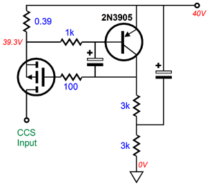
This is very much an active current regulator, as the PNP transistor is constantly checking the voltage drop across the MOSFET's source resistor. We can create a less aggressive design, by adding a resistor and capacitor.
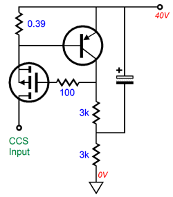
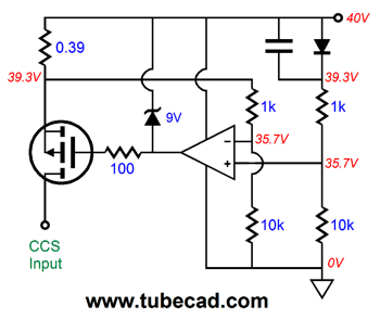
NOw the PNP transistor only sees the DC voltage across the 0.39-ohm resistor. Here is another possibility.
The OpAmp strives to keep its inverting and non-inverting inputs at the exact same voltage potential at all times. The only way it can achieve its goal is ensure that the MOSFET' conduction is steady and fixed at the desired value that maintains the same voltage drop across the 0.39-ohm resistor as is developed across the diode. Note how the B+ voltage can fall by 10 volts or rise by 10 volts and yet a fixed amount of current will flow. I know that many fear capacitor-coupling of power amplifiers. (Yet they show no equal fear for the capacitors within the power supply, oddly enough.) Well, we can create a capacitor-less output stage with the aid of a bipolar power supply.
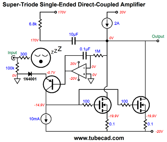
The OpAmp in the center defines a DC servo loop that eliminates the DC offset from the output. If the output strays upward in voltage, the OpAmp sees a positive signal at is inverting input, so its output swings sufficiently negative to bring the output back to 0V. This works indirectly as the PNP transistor will follow the OpAmps output, making the triode's cathode see a more negative cathode voltage, which will prompt increased current flow through the triode, which will present a more positive gate voltage to the two MOSFET, which in turn will increase their conduction, which will pull the output down to 0Vdc again. Mind you, the DC servo loop will ignore AC signals above about 2Hz. Okay, what happens if our triode is missing from its socket or its has yet to wake up and begin conducting in earnest?
Nothing, thank God, or rather, thank the diode. The safety diode becomes forward biased and completes the circuit for the PNP transistor and CCS, so the output MOSFETs still get the required gate voltage to achieve the required idle current. Once the tube heats up and begins to conduct, the diode becomes reversed biased, as the cathode voltage climbs to 2V; and the diode ceases to conduct, thereby falling out of the circuit.
Next Time
User Guides for GlassWare Software Since I am still getting e-mail asking how to buy these GlassWare software programs:
For those of you who still have old computers running Windows XP (32-bit) or any other Windows 32-bit OS, I have setup the download availability of my old old standards: Tube CAD, SE Amp CAD, and Audio Gadgets. The downloads are at the GlassWare-Yahoo store and the price is only $9.95 for each program. http://glass-ware.stores.yahoo.net/adsoffromgla.html So many have asked that I had to do it. WARNING: THESE THREE PROGRAMS WILL NOT RUN UNDER VISTA 64-Bit or WINDOWS 7 & 8 or any other 64-bit OS. One day, I do plan on remaking all of these programs into 64-bit versions, but it will be a huge ordeal, as programming requires vast chunks of noise-free time, something very rare with children running about. Ideally, I would love to come out with versions that run on iPads and Android-OS tablets.
//JRB |
Kit User Guide PDFs
And
High-quality, double-sided, extra thick, 2-oz traces, plated-through holes, dual sets of resistor pads and pads for two coupling capacitors. Stereo and mono, octal and 9-pin printed circuit boards available.
Designed by John Broskie & Made in USA Aikido PCBs for as little as $24 http://glass-ware.stores.yahoo.net/
The Tube CAD Journal's first companion program, TCJ Filter Design lets you design a filter or crossover (passive, OpAmp or tube) without having to check out thick textbooks from the library and without having to breakout the scientific calculator. This program's goal is to provide a quick and easy display not only of the frequency response, but also of the resistor and capacitor values for a passive and active filters and crossovers. TCJ Filter Design is easy to use, but not lightweight, holding over 60 different filter topologies and up to four filter alignments: While the program's main concern is active filters, solid-state and tube, it also does passive filters. In fact, it can be used to calculate passive crossovers for use with speakers by entering 8 ohms as the terminating resistance. Click on the image below to see the full screen capture.
Tube crossovers are a major part of this program; both buffered and un-buffered tube based filters along with mono-polar and bipolar power supply topologies are covered. Available on a CD-ROM and a downloadable version (4 Megabytes). |
||


| www.tubecad.com Copyright © 1999-2015 GlassWare All Rights Reserved |