| John Broskie's Guide to Tube Circuit Analysis & Design |
24 December 2015
Gratuitous Christmas Image
Visit the GlassWare store for more details.
The Cathode-, Emitter-, Source-Resistor Solution
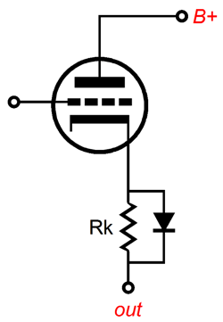
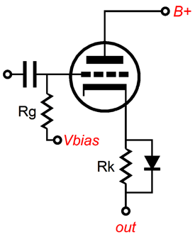
Our goal is to achieve two transconductances, the first half the value of the second. Since we can only add transconductance by adding more triodes, we must find a way to half the triode's existing transconductance. The answer is to select an un-bypassed cathode resistor that will effectively halve the triode's gm. The triode's trinity of formulas are: Mu = rp · gm, rp = mu/gm, and gm = mu/rp The last formula can be expanded to reveal the effective gm of a triode with an un-bypassed cathode resistor gm' = mu / (rp + [mu + 1]Rk) Thus, if we want gm' to equal gm/2, rp must equal (mu + 1)Rk, so we get the following equation: Rk = rp / (mu +1) For example, given a triode with a mu of 10 and an rp of 1k, its gm would equal 0.01A/V and a cathode resistor of 90.9 ohms would halve its transconductance. Now, the next step is to set the required cathode voltage, which in turn will set the required idle current, as I = Vk/Rk. Required cathode voltage? The ideal cathode voltage must equal half of the diode's forward-bias voltage, the voltage differential that allows the diode to conduct current. Why half? If the triode's current conduction has doubled, then the opposing triode in the push-pull output stage must be cutting off, which means that the output stage is leaving class-A and entering class-B operation. Okay, but what if the require cathode resistor value does not establish the desired idle current? While it might, more likely it won't, so a negative bias voltage must be applied to the grid; in other words, the triode will enjoy both cathode and grid bias. For example, if the example diode's forward bias voltage was 1V, then the cathode voltage at idle must equal 0.5V, which means that an idle current of 5.5mA is required to develop the 0.5V voltage drop across the 90.9-ohm cathode resistor. And if the example triode required -9.5V of grid voltage to establish 5.5mA of idle current with its 100V of plate voltage, then a grid voltage of -9V would be require, as the cathode resistor will contribute 0.5V of cathode bias voltage. In other words, the cathode-to-grid voltage will equal -9.5V.
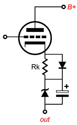
Of course, we could have just used two cathode resistors, one bypassed by a diode, the other by a large-valued capacitor; thus, allowing us to forgo using negative grid bias altogether. I, however, wouldn't go down this route. Why not? The whole point of the design is to create a class-AB output stage that exhibits a constant-transconductance. This means that although the idle current is a lean 5.5mA, we can expect huge output current swings closer to 55mA, which will serve to charge up the bypass capacitor, throwing the output stage into an ever leaner idle current, perhaps cutting off altogether. In contrast, with a class-A push-pull output stage, the bypass capacitor sees an unvarying cathode voltage, so no charge up can occur. One workaround would be to use a zener diode in place of the bottom cathode resistor.
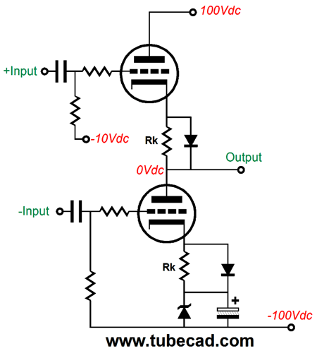
Bear in mind that I have only shown half of a tube-based, push-pull output stage, which could be a Futterman-like totem-pole arrangement or a Circlotron or classic transformer-coupled output stage, like this one:
In the above schematic, we see a zener used to establish cathode biasing of the two output tubes, but we could just as easily have used grid bias instead. Here is a totem-pole OLT output stage with triodes.
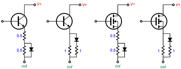
Note how the zener is only used with the bottom triode. (A second zener can be place between the top triode's plate and the B+ connection, which would equalize the cathode-to-plate voltages between triodes.) Moving on to solid-state devices, such as MOSFETs and transistors, the same diode-resistor tricks can be used, but with some modification, as these solid-state output devices exhibit such high transconductance that too small an emitter or source resistor could be used, as it would require too high an idle current to achieve the desired voltage drop equal to half the diode's forward bias voltage. Indeed, we can just assume a near infinite transconductance for most modern solid-state output devices. The workaround is to use two added resistors with the single diode.
On the left we see the two 0.5-ohm emitter resistors in series, so at idle the transistor exhibits a gm equal to 1A/V; but as the transistor leaves its class-A window of current conduction, the gm doubles to 2A/V. The required emitter voltage is equal to the diode's turn-on voltage. On the right, the second configuration places the diode in series with extra emitter (or source resistor), which will force an emitter (or source) voltage equal to half of the diode's forward bias voltage. Here is the complete output stage (OPS).
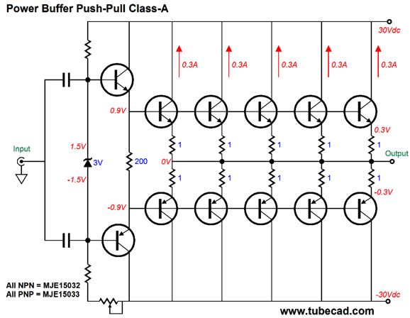
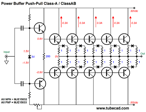
Once again, at idle, each output transistor (or MOSFET) exhibits a gm that doubles upon entering class-B operation, creating a constant-gm output stage. Now, let's return the interesting class-A power buffer design that was shown in my last post.
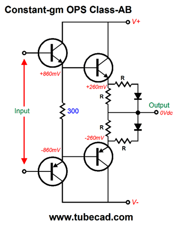
The problem this design faced was load impedance below 8 ohms, which would throw the output stage out of the class-A window of operation. Well, we can apply the diode-and-resistor trick to this design.
The added diodes and emitter resistors allows the output stage to exhibit a constant gm and, thus, a constant output impedance.
The Class-AB + Class-C Solution
To quote Nietzsche again, which is one of my favorite and most annoying habits, “What is done out of love takes place beyond good and evil.” Well what is done in high-end audio takes place beyond good and bad engineering. What!? Good engineering is the art and practice of achieving the desired goal by the simplest and cheapest means. Yes, other engineering goals exist, such as safety, marketability, productibility, and serviceability, but cost predominates, as cost constrains all the other goals. For example, specifying diamond-coated pistons in a family car is bad engineering, but a good choice in a racecar, as the racecar's objective was never cheaply moving a racedriver from point A to point B. Similarly, high-end audio has escaped the gravitational pull of good engineering as neither the label "simple" nor "cheap" apply to high-end audio. Audiophiles are willing to pay an extra 200% for a 2% increase in sound quality. In addition, since over 50% of the cost of high-end audio gear lies in its cosmetics, the added cost of a few $1 solid-state output devices is not too extravagant. (With WE 300B tubes on the other hand…) You undoubtedly know what class-A, class-AB, and class-B are, but do you know what class-C is? Class-C is never used exclusively in audio amplifiers, as it produces infinite distortion at low levels of output, as there is no output at low levels. At idle, neither output device in a class-C push-pull output stage conduct any current and they do not begin to conduct until some threshold input signal is reached. Although such a cool-running amplifier would warm the heart of global-warming-anxiety mongers, your ears would complain bitterly. Note my assumption that an amplifier putting out no output signal is equal to infinite distortion. This is an interesting philosophical problem: what does infinite distortion sound like? For example, if you play your favorite rap CD and hear a late Beethoven string quartet instead, is that infinite distortion? It would certainly be the opposite of what you wanted to hear, but would it be infinitely distorted? What if the input signal came out with inverted phase, could this be infinite distortion, as it is the the perfect inversion of the input signal. No, as half the music we hear is phase inverted. Yes, phase inversion makes a difference, but it does not make an infinite difference. Surely, the infinitely opposite of something is nothing. Okay, let's start with just class-AB + class-C. If we add two class-C output devices to a conventional class-AB output stage and if we carefully set the transition timing so that a class-C devices turn on just as the opposing class-AB device cuts off, we end up with class-AB+C, which would exhibit a constant transconductance. If we screw up the timing, we screw up big, as we will create either two gm speed bumps or two gm divots. (Or, perhaps, we only screw up small, as the ear may prefer the two sonic discontinuities as they would occur only at higher output swings, where the ear may prove more forgiving.)
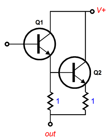
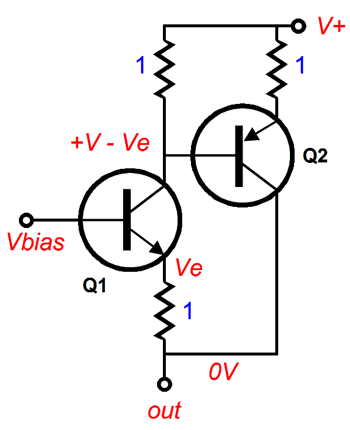
Here is one possible configuration (only half of the push-pull output stage is shown).
Transistor Q1 runs in class-AB, while Q2 runs in class-C, as it is completely turned off at idle and only begins to conduct when Q1 doubles its current conduction, as twice its idle current flow develops a large enough voltage drop across the 1-ohm emitter resistor to turn on Q2. Once on, transistor Q2 will effectively double Q1's transconductance, making up for leaving the overlap region of doubled gm. At idle, transistor Q1's emitter voltage must equal one half the transistor Q2's base-to-emitter-turn-on voltage. In a typical lean class-AB transistor power amplifier, setting the desired idle current is a nerve-racking affair, as the transistor's turn-on voltage varies with its temperature, so temperature-tracking voltage-multiplier circuit is used to present a varying bias voltage to the output transistors. Well, in contrast, with a class-AB+C output stage being run with a heavy idle current and a much larger voltage drop across the emitter resistors, the biasing need not be so finicky an affair. Alternatively, we could use a compound configuration, wherein an NPN transistor is paired up with a PNP transistor.
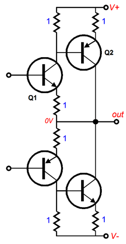
Note that at all times in a class-AB+C push-pull output stage consisting of four output transistors, both an NPN and PNP transistor are conducting.
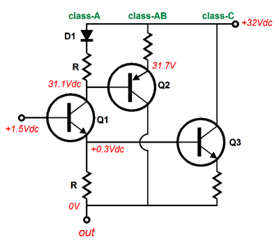
This may prove a feature, as rarely do NPN and PNP transistors exactly match each other, so by having both types always in conduction, the mismatch may largely be erased. On the other hand, this configuration will produce slightly less output wattage, as the added collector resistor will incur a voltage drop, which will subtract from the potential output voltage swing. Of course, with transistors, this subtraction will prove small, but with MOSFETs, with their hugely greater turn-on voltages, the reduction in potential output power will prove much worse. Another configuration is to let a class-A driver transistor drive both the class-AB and class-C output transistors.
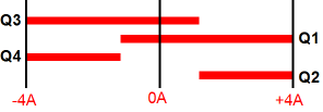
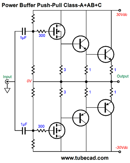
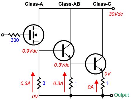
Note the added diode, whose forward-bias voltage should equal the transistor's turn-on voltage. Transistor Q2's emitter voltage must equal half of Q3's turn-on voltage. Now, transistor Q1's emitter resistor will see the same voltage drop that Q2's emitter resistor sees, so when Q2 doubles its idle current conduction, transistor Q3 will begin to turn on, doubling the effective gm and establishing a constant gm for the output stage. Now, we move on to class-A + class-AB + class-C. Since class-AB + C creates a constant-gm output stage, adding class-A (already a constant-gm mode of operation) to do it also results in a constant-gm output stage. In the following example, a hybrid circuit is shown, with the MOSFETs in the leading role. (I assume that lateral MOSFETs, such as the BUZ901 & BUZ906, will be used, since only two are needed per channel.)
Ideally, the two power MOSFETs never turn off, which means that they run in class-A. One pair of NPN-PNP transistors run in class-AB, a very rich class-AB at that, while the other pair of transistors run in class-C and only turn on when more than 4W is delivered to an 8-ohm load.
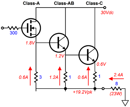
The N-channel MOSFET and class-AB NPN transistor will run hot, as they must each dissipate 9W at idle, while the class-C transistor runs cool, due to it being completely cut off at idle. How much power can this output stage deliver into an 8-ohm load? We find the answer by imagining that the MOSFET's current conduction is at twice its idle value, in other words, 600mA.
A total of 2.4A of peak current flow delivers 23W into an 8-ohm load and 11.5W into a 4-ohm load. Once again, the pesky 4-ohm speaker ruins the party. The best workaround is to use more output devices.
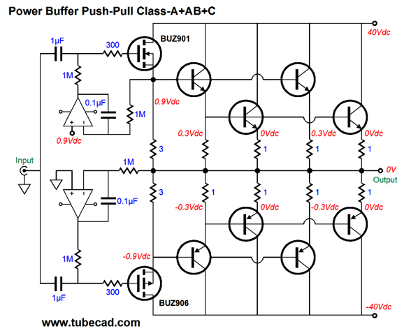
With the added output transistors, the maximum power output is 36W with both 4- and 8-ohm loads, while the MOSFETs remain in class-A operation. Because the MOSFETs both run in class-A and offer such a high input impedance, we can use two DC servos, one to eliminate a DC offset and one to establish the MOSFET's idle current. I had gobs more to write, but my fingers are giving out. Next time.
Next Time
User Guides for GlassWare Software
For those of you who still have old computers running Windows XP (32-bit) or any other Windows 32-bit OS, I have setup the download availability of my old old standards: Tube CAD, SE Amp CAD, and Audio Gadgets. The downloads are at the GlassWare-Yahoo store and the price is only $9.95 for each program. http://glass-ware.stores.yahoo.net/adsoffromgla.html So many have asked that I had to do it. WARNING: THESE THREE PROGRAMS WILL NOT RUN UNDER VISTA 64-Bit or WINDOWS 7 & 8 or any other 64-bit OS. I do plan on remaking all of these programs into 64-bit versions, but it will be a huge ordeal, as programming requires vast chunks of noise-free time, something very rare with children running about. Ideally, I would love to come out with versions that run on iPads and Android-OS tablets. //JRB |
Kit User Guide PDFs
E-mail from GlassWare Customers
High-quality, double-sided, extra thick, 2-oz traces, plated-through holes, dual sets of resistor pads and pads for two coupling capacitors. Stereo and mono, octal and 9-pin printed circuit boards available.  Aikido PCBs for as little as $24 http://glass-ware.stores.yahoo.net/ Support the Tube CAD Journal & get an extremely powerful push-pull tube-amplifier simulator for TCJ Push-Pull Calculator
TCJ PPC Version 2 Improvements Rebuilt simulation engine *User definable
Download or CD ROM For more information, please visit our Web site : To purchase, please visit our Yahoo Store: |
|||


| www.tubecad.com Copyright © 1999-2015 GlassWare All Rights Reserved |