| John Broskie's Guide to Tube Circuit Analysis & Design |
30 January 2016
More Tube Output Stages
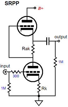
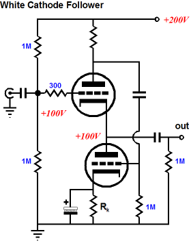
The SRPP, the White cathode follower, and the SRCFPP belong to this group, as all three use a current-sense resistor to create the needed and missing inverted input signal for the indirectly driven triode, so that push-pull operation is made possible. All three are extremely load dependent and all three must be run in strict class-A, for if the the triode that receives the external input signal ever cuts off completely, so too will the current through the current-sense resistor, thereby ceasing to generate the inverted signal that the other triode requires. Strict class-A watts are as different from advertising watts as reality is from Hollywood movies. Here is an example: a reader wrote to me about a year ago, detailing his goal of building a 240W, class-A, push-pull power amplifier that used eight KT88 tubes. In two words, im possible. How so, he asked. The answer: all inductively loaded class-A amplifiers, either single-ended or push-pull types, can never exceed 50% efficiency. Period. That is the physics behind the reality. Indeed, no class-A amplifier can exceed 50% efficiency. Thus, in order to get 240 class-A watts from eight KT88 tubes, each would have to dissipate (240W x 2) / 8 watts, or 60 watts each at idle. This assumes that the output transformer's primary and secondary offer zero DCR and that the KT88 presents an rp of 0 ohms, neither of which can be true. Moreover, the KT88 plate dissipation limit is 35W and its screen limit is 6W. The reader was not swayed by my arguments, as he had seen highly-rated class-A, 60W stereo power amplifiers that held only four KT88 output tubes. I do not doubt that 60W is what the amplifier's data sheet and its glossy ad and what the audio reviewer stated as its class-A power output, alas. Many do not know the difference between peak watts and average watts. Few bother to measure, relying on appearance rather than testing. It certainly looks like a 6oW amplifier; therefore, it must be a 60W amplifier. Alas, no. Look, just a great cook can produce fantastically tasty dishes yet know next to nothing about nutrition or chemistry, a highly successful tube amplifier maker can produce lovely-sounding amplifiers yet know next to nothing about physics, math, and electronics. He simply uses old, proven designs that were created by someone who did know all about physics, math, and electronics; he then played around with part types and values until he was pleased with the resulting sound—but he cannot cheat the universe. No one can. Conversely, someone extremely knowledgeable about nutrition or chemistry may prove a dismal cook. The ideal is someone like Leonardo, who combined supreme artistic gifts with exceptional technical understanding.
SRCFPP Power Amplifiers
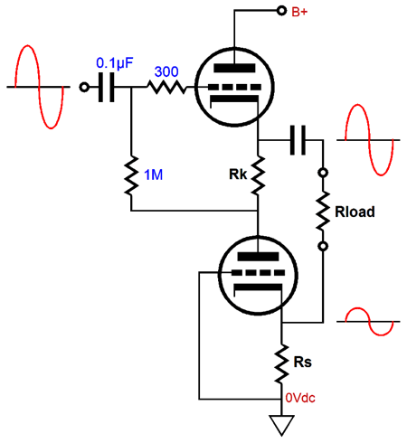
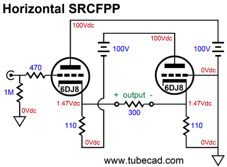
Note how the bottom triode's grid is grounded. (Reread blog post number 228 to see a single-output version of the SRCFPP that uses a floating power supply and a grounded bottom cathode.) A key feature is that the SRCFPP puts out two outputs, a positive and a negative, but not balanced outputs. The top (positive) output delivers bigger voltage swings than the bottom (negative) output. Just as importantly, both outputs are in phase with each other, not out of phase. Note how the bottom triode's cathode voltage will vary with the varying current drawn through it. If bottom triode's cathode becomes more positive, the bottom triode's current conduction will fall. (Effectively, its grid has become more negative.) If bottom triode's cathode drops in voltage, the bottom triode's current conduction will rise.
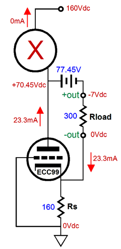
A seeming paradox this. If bottom triode's current conduction rises, then surely its cathode voltage must also rise. No, as in this topology there are two AC current paths: the bottom triode and the external load impedance. As the bottom triode's current conduction rises, the positive (the top) output swings negative, so the external load is effectively attached to a negative power supply (i.e. the large-valued coupling capacitor) and the current flowing through the load impedance will pull down the bottom triode's cathode voltage, not pull it up. Let's start with the top triode being driven to cut-off, so it conducts no current whatsoever. In other words, imagine that the top triode has been yanked from its socket.
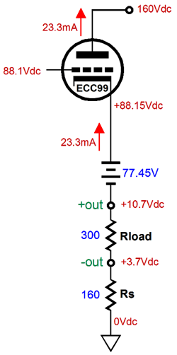
The large-valued coupling capacitor acts like a voltage source and the positive output swings to -7Vpk. Note how no current flows through the current-source resistor, as it falls outside the current-flow circuit. This means that the bottom triode's grid and cathode are at 0V. Now, we move on to the situation wherein the the top triode conducts fully and the bottom triode is cut-off. In other words, this time imagine that the bottom triode has been pulled from its socket.
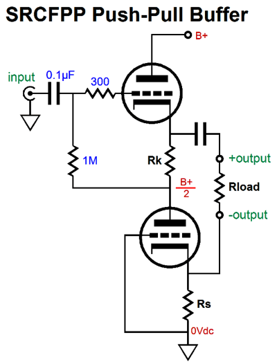
The top triode's grid and cathode are roughly at the same voltage and the charged up coupling capacitor displaces 77.45V. The result is that the positive output swings up +7Vpk relative to the negative output. Thus, we see how can get +/-6Vpk into the 300-ohm external load impedance. If you fail to understand the dynamics behind this push-pull operation, you will never understand how the SRCFPP works. Wait a minute John, these examples show +/-7Vpk, not +/-6Vpk. True enough, but we never want either triode to completely cut-off, so we limit ourselves to some value slightly less than twice the idle current, 10.9mA, so let's say 20mA, into the 300-ohm load resistance, which equals +/-6Vpk. We can readily create a standalone version of the SRCFPP buffer, as show below, where resistors Rk and Rs must match each other.
The formula for the optimal value of resistor Rs is: Rs = ( rp + 2Rload) / (mu - 1) which is the same formula for the SRPP and quite close to the White-cathode-follower formula: Ra = ( rp + 2Rload) / mu If we solve for Rload with the SRCFPP, we get the following formula: Rload = ((mu - 1)Rs - rp) /2 Why would we want to work backwards? Often we are stuck with a certain value for the sense resistor, Rs; for example, we must limit the triode dissipation to some safe limit, so we you higher-valued cathode resistor. Thus, in oder to acheive balanced push-pull operation, we must use an optimal load resistance value. How can we do that, if we cannot change the external load impedance; for example, we cannot alter our headphone impedance? The solutiuon would be to use transformer coupling.
Note that this is still a buffer circuit that provides no voltage gain; indeed, it incurs a small AC loss. This means that the input signal must swing hundreds of volts to get some decent power into the low-impedance load, as the transformer coupling winding ratio will further decrease the secondary voltage swings. This also means that the top triode's heater must have its own independent heater power source that is referenced to its cathode. The bottom triode, on the other hand, can use a ground referenced heater power source. Also note the whopping big B+ voltage of 800Vdc! My own comfort limit is about 600Vdc, as any more voltage scares the hell out of me. In addition, such high voltages are pain and expensive, as large-valued 1kV capacitors are both rare and expensive. One workaround is to use a bipolar power supply.
The same performance, but at one quarter the danger. One quarter? Just as with moving objects whose kinetic energy is proportional to the square of the velocity, in electronics the whollop is is proportional to the square of the voltage; thus, 800V is four times worse than 400V, as it is twice as large and 2² = 4. Moreover, 1200V is nine times worse than 400V, as 3² = 9. One problem with a high-voltage bipolar power supply is that most tube fanciers hate them and that using tube a rectifier is more difficult, but not impossible. So, isn't there some sneaky way to have our cake and eat it too? Well, if it is sneaking you desire, you came to the right place, as sneaky (boldly original is its AKA) is my specialty.
The above schematic assumes both a perfect inductor and a transformer, which displace no DC voltage as they offer no DC resistance. Note the 400Vdc B+ voltage and the DC ground-referenced input. Of course, in spite of what all the glossy high-end-audio ads proclaim, we never cheat physics, so although we have halved the B+ voltage, we have also doubled the current draw, bringing us to unity. In other words, this version will dissipate the same amount of power at idle as the 800V version. One problem we face is that finding high-quality chokes is difficult, as they must be built with the same care and quality materials as a high-quality output transformer. This is uncommon and, thus, expensive. One workaround would be to use two output transformers.
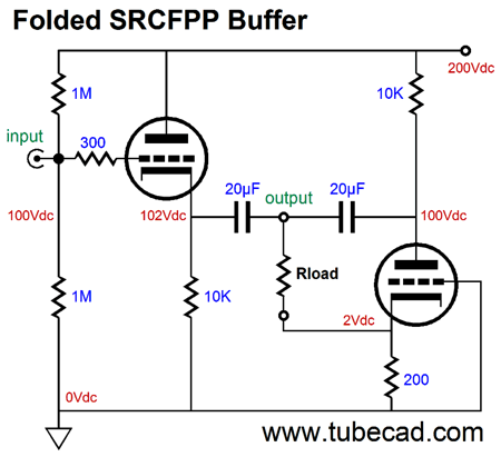
The output transformer on the right must have its primary flipped relative to the left output transformer. The 20µF capacitor effectively ties the left triode's cathode to the right triode's plate. By the way, we can apply this folding trick to the plain SRCFPP buffer, as shown below.
The two 10k resistors are effectively in parallel, so they present a 5k load to the tubes. As it stands, this circuit is a bit silly, which doesn't mean that it couldn't become wildly popular, against my wishes. It does, however, make a point. A better circuit is shown below.
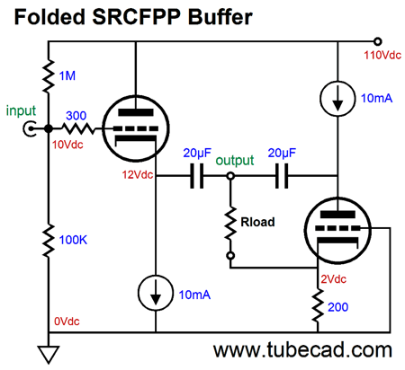
The 10k resistors have been replaced by two 10mA constant-current sources, which allows us to lower the B+ voltage by almost a half. By the way, the PSRR is excellent, coming in at roughly 1/mu. Of course, many will dislike need for solid-state constant-current sources and the two 20µF coupling capacitors. There is a workaround, but it entails the use of two power supplies, one fixed and one floating.
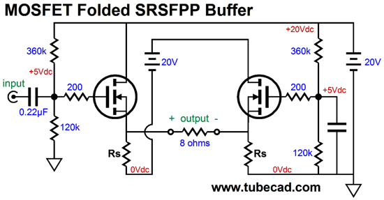
No solid-state constant-current sources and no coupling capacitors; and if the triodes are well matched, no differential DC offset. (The safer approach would be to use one coupling capacitor.) By the way, I know that hundreds of thousands (if not millions) of audiophiles long to build a Nelson Pass Zen single-ended power amplifier. Well, the following push-pull SRSFPP power buffer offers some advantages over the famous Zen.
Note the name, SRSFPP, which stands for Single Reflexive Source Follower Push Pull. No voltage gain is created, but many class-A, push-pull watts can be delivered to the 8-ohm load. How many? It depends on the idle current (and power supply voltages). With an idle current of 1A, 16W is possible, as 2A of peak current flow is possible. At idle the buffer will dissipate 40W, so the efficiency comes in at 40%. Not bad. The assumption is that matched N-channel MOSFETs will be used. On the other hand, the following version uses a DC servo loop to null any differential DC offset across the speaker.
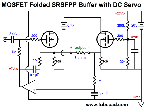
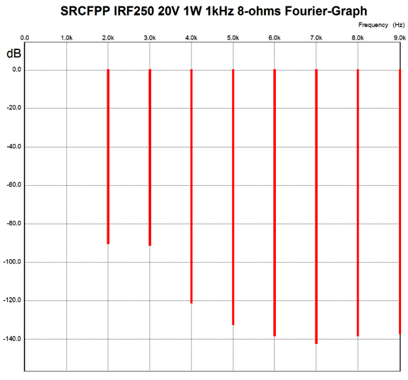
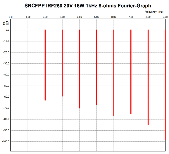
(Aren't you glad that I didn't start with this schematic?) Note the absence of any negative power-supply rail. Note how the DC servo seeks to establish the same DC voltage at the positive output as there appears on the negative output. Note how the 1M resistors and the 0.1µF capacitors filter away the AC signal. The missing bit of information is the value for resistor Rs. In SPICE simulations with the IRF250 MOSFET, 0.22 ohms was close to perfect (and the bias voltage came in at 4.71Vdc for the MOSFETs. At 1W of output at 1kHz into 8 ohms, the following SPICE Fourier graph reveal the harmonic structure.
Impressive, as the THD comes in at below 0.01%, with a beautiful single-ended quality. The following graph is at full output, 16W.
Also impressive, as the THD is just a tad over 0.1%. Of course, both graph assume that a near-perfect signal source is used and that the MOSFET are perfectly matched. (I have been told that if a pair of power MOSFETs come out of the same production run, they will will be very closely matched as is, for most of the slop was long ago removed from MOSFET production.) Wait a minute John, what about the missing voltage gain? My view is since it is easy to get a tube-based line stage to swing the needed +/-17Vpk, we don't need any voltage gain from the SRSFPP. For example, a 6DJ8-based Aikido line stage delivers a gain of about 16 and very little distortion. Returning to tube designs, one issue with the previous SRCFPP power buffer that held two output transformers is that the output transformers had to hold an air-gap, as their primaries saw a steady DC current flow. Since good single-ended, air-gapped output transformers are more difficult to find than good push-pull, no-air-gap output transformers, the following design is appealing.
The output transformer sees no DC differential voltage, thus no sustains no DC current flow. I get a lot e-mail concerning the four-300B OTL amplifier that puts out 1 watt, which was designed by Bruce Rozenblit.
Well, the above circuit uses no solid-state current source and could use two 300B, but it would deliver far more than just 1W. True it is not an OTL, but then it uses no coupling capacitor on the output either and would offer far more power output and far lower distortion and output impedance. Or, we could use an ECC99 or 5687 tube to drive 50-ohm headphones. Of course, we are not limited to such a low B+ voltage, as 400Vdc or more could be used. Nor are we limited to triodes, as pentodes, such at the EL34 or KT120 could be used. Note that secondary does not have to be grounded, so a balanced output is easily obtainable. I am going to stop right here. Ready for this, I had planned on making this post three times longer!
Next Time
User Guides for GlassWare Software Since I am still getting e-mail asking how to buy these GlassWare software programs:
For those of you who still have old computers running Windows XP (32-bit) or any other Windows 32-bit OS, I have setup the download availability of my old old standards: Tube CAD, SE Amp CAD, and Audio Gadgets. The downloads are at the GlassWare-Yahoo store and the price is only $9.95 for each program. http://glass-ware.stores.yahoo.net/adsoffromgla.html So many have asked that I had to do it. WARNING: THESE THREE PROGRAMS WILL NOT RUN UNDER VISTA 64-Bit or WINDOWS 7 & 8 or any other 64-bit OS. One day, I do plan on remaking all of these programs into 64-bit versions, but it will be a huge ordeal, as programming requires vast chunks of noise-free time, something very rare with children running about. Ideally, I would love to come out with versions that run on iPads and Android-OS tablets.
//JRB |
Kit User Guide PDFs
And
High-quality, double-sided, extra thick, 2-oz traces, plated-through holes, dual sets of resistor pads and pads for two coupling capacitors. Stereo and mono, octal and 9-pin printed circuit boards available.
Designed by John Broskie & Made in USA Aikido PCBs for as little as $24 http://glass-ware.stores.yahoo.net/
The Tube CAD Journal's first companion program, TCJ Filter Design lets you design a filter or crossover (passive, OpAmp or tube) without having to check out thick textbooks from the library and without having to breakout the scientific calculator. This program's goal is to provide a quick and easy display not only of the frequency response, but also of the resistor and capacitor values for a passive and active filters and crossovers. TCJ Filter Design is easy to use, but not lightweight, holding over 60 different filter topologies and up to four filter alignments: While the program's main concern is active filters, solid-state and tube, it also does passive filters. In fact, it can be used to calculate passive crossovers for use with speakers by entering 8 ohms as the terminating resistance. Click on the image below to see the full screen capture.
Tube crossovers are a major part of this program; both buffered and un-buffered tube based filters along with mono-polar and bipolar power supply topologies are covered. Available on a CD-ROM and a downloadable version (4 Megabytes). |
||


| www.tubecad.com Copyright © 1999-2016 GlassWare All Rights Reserved |